AMAZON multi-meters discounts AMAZON oscilloscope discounts
Introduction
In Part 2 we marked out the case ready for installation of the modules when they are completed. In this part, the building of the variable frequency oscillator (VFO) and mixer will be described. This will produce a type of receiver known as direct-conversion, because it converts the radio frequency (RF) signal directly into an audio-frequency (AF) signal which we can hear in a loudspeaker after amplification. A block diagram of the system is shown in Figure 1. The modifications needed to make a full superheterodyne receiver will be left until later.
The direct-conversion receiver covers the 80 meter amateur band and will receive both Morse (CW) and speech (SSB) signals. The audio amplifier was covered in Part 1, so your Colt is rapidly taking shape! By the time your construction has reached the end of this part, you will have a receiver ready to use, even if the project is not yet complete!
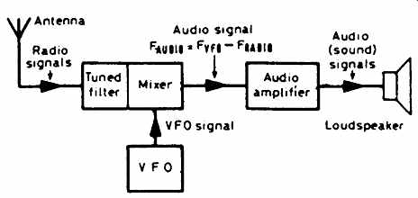
Figure 1 Stages of direct conversion receiver
The direct conversion process
Like most things in radio, the principles of direct conversion are not difficult. From the aerial, the signal we want to hear is selected by the tuned filter , which rejects the signals we don't want. The signal then enters the mixer , along with the signal from the VFO. The VFO produces a sine wave whose frequency can be varied across the whole of the 80 meter amateur band (3.5-3.8MHz), by turning the knob on the tuning capacitor, VC1.
The mixer produces, at its output, two signals; one signal is at the frequency of the sum of the signal and VFO frequencies, the other is at the difference of the two frequencies. It is the latter that we want. Let's look at the numbers involved. If the signal is at 3650 kHz and the VFO is at 3651 kHz, then the sum frequency is 7301 kHz, and the difference frequency is 1 kHz.
If we feed the output of the mixer into our audio amplifier, the 7301 kHz signal is automatically removed (it is far too high to be considered an audio signal!) and the resulting 1 kHz signal is amplified and fed to the speaker, producing a note which we can hear! Building the VFO
Figure 2 shows the circuit of the VFO. It is a tried and tested circuit, and should work first time. It uses a field-effect transistor (FET) for TR1, the oscillator itself. RFC is a radio-frequency choke, a coil of wire which will pass a direct current (DC) but which will prevent radio-frequency (RF) signals getting through.
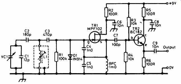
Figure 2 The variable-frequency oscillator uses a field-effect transistor
(FET)
All VFOs have a tuned circuit which, in this case, is formed by the coil L1 and the capacitors C1 and VC1. The frequency will also be affected to some extent by C2, C3, C4 and C5. Transistor TR2 is an emitter follower , a stage which gives no voltage gain but provides a good buffer stage, isolating the VFO from the effects of the stages that follow it. When building a VFO, the parts must be securely mounted. If components move, so does the frequency! At worst, the oscillation will become unstable and the VFO will be useless. Keep the component leads as short as possible -- this improves their mechanical stability as well as their electrical stability! Mount the parts on the printed-circuit board (PCB) or matrix board and, when completed, the VFO should look like the one shown on the left in the photo. Make sure that TR1, TR2 and D1 are the right way round.
On completion, check the component positions then mount it in the case as shown in the photograph, to the left of the tuning capacitor when viewed from the rear. The VFO coil, L1, will need some adjustment, but that will have to wait until the mixer is built. Connections to the other boards are made with screened cable.
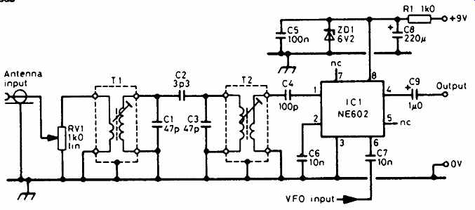
Figure 3 The mixer board has a bandpass filter and stabilized supply
The mixer board
So far, we have an audio-frequency (AF) amplifier and a VFO; the addition of a mixer board gives us a complete direct-conversion receiver for 80m. The mixer circuit diagram is shown in Figure 3. Let's follow the signal path.
_ From the aerial, the RF signal goes to the gain control potentiometer, RV1. This reduces very strong signals, to prevent them overloading the mixer.
_ To select the required band of signals, a bandpass filter is made up of RF transformers T1 and T2; these are tuned by C1 and C3, and are coupled together by C2.
_ After the filter, the signal is coupled into the integrated circuit (IC) mixer type NE602, by the capacitor C4. Capacitors C5 and C8 decouple the supply line, to prevent unwanted signals on the supply from disturbing the VFO operation. The use of the term decouple is exactly the opposite of couple; when two circuits are coupled together, the signal passes from one to the other; when two circuits are decoupled, signals cannot pass from one to the other.
_ The NE602 works with a 6V supply; it is produced here from the 9V supply by the Zener diode ZD1 and the resistor R1. ZD1 operates at 6.2V, and gives a steady output for the mixer. The audio output from the mixer appears at pin 4 or IC1. This is taken to the audio amplifier board via C9 and the volume control (see Part 1).
Care must still be taken to insert some components the right way round.
These are the electrolytic capacitors, C8 and C9, the Zener diode, ZD1, and the integrated circuit, IC1. Check all component positions and make sure all your soldered joints are bright and shiny.
Putting it together
The interboard wiring, shown in Figure 4, uses screened cable; ideally, this should be thin coaxial cable, but screened microphone cable is suitable. The diagram shows how the two controls, the RF Gain and Volume, are connected to the boards. The leads marked '+9V' are all connected to the battery supply via a miniature on/off toggle switch. Double check all connections before connecting the battery.
Setting the VFO
Very little adjustment is needed to get the receiver going. Firstly, the VFO must be adjusted to cover the required band, in this case 3.5-3.8MHz.
If you have a frequency counter, connect it to the output of the VFO. If you haven't, read this part anyway so you understand the process, then another means of setting the VFO will be given especially for you! Rotate VC1 until the vanes are fully meshed. Very carefully, adjust the core of the VFO coil (L1) with a plastic trimming tool so that the frequency approaches and settles at 3.500MHz. When you rotate VC1, the frequency should increase to at least 3.800MHz at the far end of its travel.
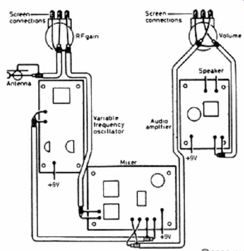
Figure 4 Make sure that interconnections between the boards are correct,
including cable screens
In the absence of a frequency counter, borrow a communications receiver, set it for SSB reception (USB or LSB) on exactly 3.500MHz. Set VC1 with the vanes fully meshed and turn the core of L1 in both directions until you hear a whistle in the communications receiver. Rotate the core so that the whistle reduces in frequency. It will eventually fade out at around 200Hz; turn the core a little further and then leave it at that position. Rotate VC1 right to the other end of its travel, and search for the whistle with the tuning knob of the communications receiver. Check that the VFO frequency is at least 3.800MHz.
Then, whichever method you are using for frequency measurement, mark the dial with frequency steps of 50 kHz. Setting and calibration are finished! Setting the mixer
Again, there are various ways of doing this. If you have a signal generator, inject a signal at a frequency within the 80m band, and adjust the cores of T1 and T2 sequentially for maximum output.
If you haven't a signal generator, connect an aerial to the mixer input, set the RF Gain to maximum (fully clockwise), and find a consistent signal. Adjust the volume control to a comfortable level. Rotating the core of T2 with your trimming tool, maximize the output. Then do the same with T1, although this will have much less effect. Find another station, and check that the positions of the cores aren't too different for a maximum signal.
You may find that your receiver benefits from the insertion of an aerial tuning unit (ATU) between the aerial and the input, to compensate for the impedance of your aerial not being 50 ohm. A design for such an ATU is presented in another part of this series. If the signals are still weak, connect the ATU to the junction of C1 and C2 via a 100 pF capacitor.
Try listening!
Remember that 80m is a variable band. During daylight hours, your will hear Morse signals at the lower end of the band, and some British and closer continental stations between 3.7 and 3.8MHz. In the evenings, stations up to 1000 miles away should be heard. Look for Novices around 3.7MHz!
============
Parts list -- VFO board
Resistors: all 0.25 watt, 5% tolerance
R1 100 kilohms
R2, R5, R6 100 ohms
R3, R4 10 kilohms
RV1 1 kilohm linear
Capacitors:
C1 12 picofarads (pF) polystyrene
C2 100 picofarads (pF) polystyrene
C3 470 picofarads (pF) polystyrene
C4, C5 1 nanofarad (nF) polystyrene
C6, C8, C9 10 nanofarads (nF) polystyrene
C7 100 picofarads (pF) min. ceramic
VC1 140 + 140 picofarads (pF) variable
Semiconductors:
TR1 MPF102 FET
TR2 BC182 npn
D1 1N914 silicon
Inductors:
L1 Toko KANK3334
RFC 1mH RF choke
Parts list -- mixer board
Resistors: 0.25 watt, 5% tolerance
R1 1 kilohm
VR1 1 kilohm potentiometer (linear)
Capacitors:
C1, C3 47 picofarads (pF) min. ceramic
C2 3.3 picofarads (pF) min. ceramic
C4 100 picofarads (pF) min. ceramic
C5 100 nanofarads (nF) min. ceramic
C6, C7 10 nanofarads (nF) min. ceramic
C8 220 microfarads (uF) electrolytic 16V
C9 1 microfarad (uF) electrolytic 16V
Integrated circuit:
IC1 Philips NE602 or NE602A
Additional items:
T1/T2 Toko KANK3333
On/off switch
Miniature toggle switch
============
The next part . . .
The IF amplifier and the Beat-Frequency Oscillator will be added to convert the Colt into a superheterodyne receiver.