AMAZON multi-meters discounts AMAZON oscilloscope discounts
Introduction
It is said that the pleasure of sending and receiving Morse code more than compensates for the learning effort needed. Transmitters for Morse code can be much simpler than those needed for any of the speech modes.
Many people choose to learn sending and receiving on their own. It can be much more fun if you have someone to learn with you, and it is for this reason that the following project arose. It comprises just one small circuit, and you build an identical circuit for each of the people who want to learn with you. All the individual circuits are connected with their output leads in parallel, as the two-way circuit of Figure 1 shows.
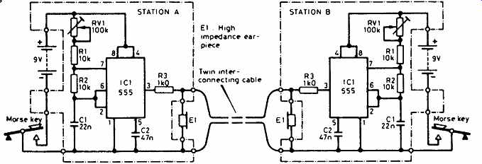
Figure 1--The circuit diagram shows two stations, but you could connect several
more if needed.
A simple circuit
This diagram shows two identical circuits, as would be used if two people wanted to learn together. The circuit centers around our old friend the NE555 integrated circuit (IC). As it is connected here, it works as an astable multivibrator , a daunting name for what is essentially an oscillator. Each circuit is self-contained, having its own battery, Morse key, sounder and plastic box. The Morse key makes and breaks the power supply to the circuit, thus turning on and off the note emitted by the earpiece. The frequency of the note is controlled by the variable resistor RV1, resistors R1 and R2, and the capacitor C1. The range given by RV1 is approximately from 500Hz to 2200Hz.
R3 protects the output of the IC against accidental shorting either to the 0V or to the 9V supply rails. For best results, a crystal earpiece or high impedance headphones should be used. You could try Walkman-type headphones, but the volume may be too low for you.
The units may be interconnected with thin twin cable (the sort used for wiring doorbells) and can be comfortably separated by 25m, more than enough to communicate between rooms, or even with a neighbor!
In use
When an operator presses his key, the note is heard by himself and by everyone else who is connected. If more than one key is pressed at the same time, two or more notes are heard by everyone! It helps if each person adjusts his own potentiometer, RV1, to give a note which is different from the others. When one operator stops sending, the other can start immediately, without pausing to change from transmit to receive. In practice, this technique is known as full break-in.
The current drawn by the circuit is only 10 milli-amps (mA) when the key is down, meaning that the life of a typical PP3 battery will be virtually its shelf-life! No switch is needed, because the key acts as the switch. The current drain will be even less if the NE555 is replaced by an ICM7555 IC.
It has exactly the same pin connections as the NE555, so no circuit modifications are needed.
The circuit board
The circuit is constructed easily on a small piece of Veroboard of the copper strip type. Figure 2 shows the layout of the prototype, the board measuring 18 holes by 10 strips. Be aware that there is no row 'I' when you are transferring mental images of where the parts are to real positions on the board! Break the copper tracks where shown with a 3mm ( 1/8 inch) twist drill, rotated carefully between thumb and forefinger. Hold the board up to a bright light to make sure that the tracks are completely broken and that there are no fragments of copper swarf shorting adjacent tracks. Then, solder in the wire links shown in Figure 2, followed by the resistors, RV1, and the capacitors, C1 and C2. Solder the battery connector leads to tracks A and G, G being positive. Use insulated wire to connect from the board to the jack sockets used as connectors for the key and the earphones. If you use different sized jack sockets (i.e. 2.5mm and 3.5mm) you won't plug the earphones into the key socket! A two-screw terminal strip is useful to connect the cable runs between operators.
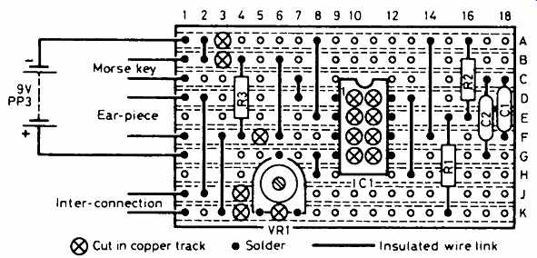
Figure 2 The Morse Duet is an easy project to build on stripboard (Veroboard)
===========
Parts list
For each board, you will need: order codes
Resistors: all 0.25 watt, 5% tolerance
R1, R2 10 kilohms M10K
R3 1 kilohm M1K0 RV1 100 kilohm min. preset (horizontal mounting) UH06G
Capacitors:
C1 22 nanofarads (nF) ceramic, 25V WX78K
C2 47 nanofarads (nF) ceramic, 25V RA47B
Integrated circuit:
IC1 NE555 QH66W
Additional items:
8-pin DIL socket BL17T
Jack plug and socket 2.5mm HF76H, HF78K
Jack plug and socket 3.5mm HF80B, HF82D
Battery type PP3
Battery connector HF28F
Plastic box with lid 114 × 76 × 38mm LH14Q
Veroboard 0.1 inch with copper strips 18 holes × 10 strips JP46A
Terminal strip (two section) FE78K
Crystal earpiece LB25C
Morse key
===========
The key:
The circuit is designed to be used with a straight key (one that moves up and down). It is a requirement of the UK Morse test that a straight key is used, so it is very sensible to learn sending with a straight key before you try anything more complex! You will find many to choose from at rallies.