AMAZON multi-meters discounts AMAZON oscilloscope discounts
Introduction
A crystal calibrator is a device that produces oscillations of a precise frequency which are rich in harmonics. A harmonic is an integer multiple of the fundamental frequency; for example, if our fundamental frequency was 100 kHz (as it is in this circuit), there would be harmonics of this frequency at 200 kHz, 300 kHz, 400 kHz, and so on. These harmonics can be used, when picked up by any receiver, to calibrate that receiver, as the harmonics are quite accurate in frequency (see later for an assessment of accuracy). However, a gap of 100 kHz between harmonics is rather wide for most purposes, so we reduce this frequency to 25 kHz, so that the harmonics are then 25 kHz apart, thus producing a much more useful set of marker points. A calibrator such as this is often called a crystal marker, producing these marker points from 25 kHz to beyond 30MHz.
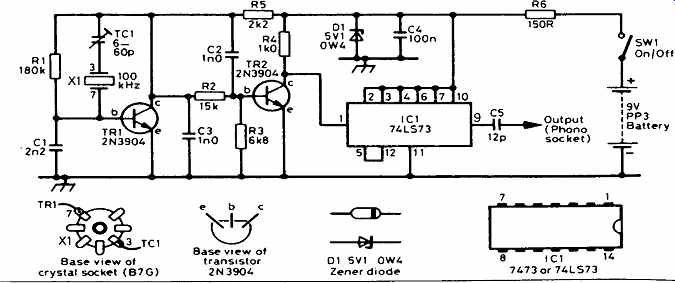
Figure 1--Circuit diagram of the calibrator which uses easily obtainable components.
The circuit
The circuit diagram is shown in Figure 1. The circuit around TR1 is the fundamental oscillator, and its frequency is controlled by the quartz crystal, X1. Even crystal oscillators are not 100% accurate, and the small trimmer capacitor, TC1, is able to 'pull' the frequency to one which is nearer the correct one. TR2 is a buffer stage, which isolates the oscillator from the rest of the circuit. It acts as a switch, and applies a good signal (switching between 0 and 5V) to the input of IC1.
IC1 is an integrated circuit which can be connected to do several things. It is connected here to divide the incoming frequency by a factor of 4, producing on pin 9 an output frequency of 25 kHz.
The combination of R6, C4 and D1 produces a supply of 5V for IC1; it would be damaged if the battery voltage were applied to it. You will no doubt be ready to assemble the circuit, so here is some information for you.
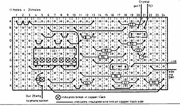
Figure 2--Stripboard, such as Veroboard, should be cut as shown to approx.
62 × 28mm.
Construction
If possible, always build a circuit in individual stages, which you can test as you go along. It is not always easy in small projects like this, but even the crystal calibrator can be split into two for construction and testing.
It is an ideal project for assembly on Veroboard of the copper-strip type; the prototype layout is shown in Figure 2, on a board measuring 11 holes by 24 strips. First of all, remove the copper strip at the locations shown, using a 3mm drill rotated between the fingers. Hold the board up to the light to ensure that there are no pieces of copper swarf bridging adjacent strips, and that the copper is completely removed where it should be! Assemble the circuit from left to right, but do not wire up anything around IC1. Be aware that the diagram shows the board from the component side. Although you can use virtually any kind of crystal, you will need to mount it firmly. If you use a small one, it can be soldered directly in position on the board. With one in a valve envelope, you will need a B7G valve (tube) holder. Be prepared to mount the circuit in a metal container; the prototype used an (empty) tin of tuna! The valve (tube) holder mounts well on any metal case.
Disconnect the aerial of your receiver, and replace it with about 30 cm of wire laid near your oscillator circuit. Connect the battery and switch on.
Tune the receiver around until you can hear a whistle on SSB. Rotate the tuning knob to reduce the frequency of the whistle and, as the whistle becomes too low to hear, you have reached one of the calibration markers, and your frequency will be an integer multiple of 100 kHz. If you are already using a calibrated receiver, you will be able to verify this. Going up or down in frequency should locate another marker 100 kHz away, and so on right through the receiver's tuning range. If the signals coming from the circuit are very weak, switch off the calibrator and connect another 30 cm piece of insulated wire to the collector of TR2, and lay it close to (but not touching) the wire from the aerial connector. Switch on an try again; you should not now have a problem! If you have access to a multimeter, check that the voltage at the collector of TR1 is very close to 5V. If it is close to 9V, you have connected the diode, D1, the wrong way round! Having verified that the oscillator is working, you can now wire up the integrated circuit socket, being careful to put the notched end of the socket pointing towards R4, the collector resistor for TR2.
Check your connections around IC1, and when you are satisfied that they are correct, line up IC1 with its socket, making sure that the notched ends are together, and press down gently to insert the IC into its socket. Insert the 30 cm piece of insulated wire into the output socket, connect the battery and switch on. You should still hear whistles in your receiver, but now they should be 25 kHz apart, rather than 100 kHz apart.
All that now remains to be done is to mount the circuit rigidly inside whatever casing your have chosen. Make sure that none of the connections under the board touch the metal case, and secure the valveholder, on/off switch and output connector to the case. You now have a completed crystal calibrator.
Calibration
The simplest way to calibrate your circuit is with a frequency counter. Most clubs will have one of these and, if not, will know someone who has! Connect it to the collector of TR2, where the frequency should be 100 kHz. Do not connect it to any part of the circuit around TR1, or you may alter the frequency you are trying to measure! If the frequency is not exactly 100.000 kHz, rotate TC1 until it is (or is as close as you can get it). Now your calibrator is as accurate as the counter with which you have calibrated it.
Accuracy
Despite your best efforts at calibration, by whatever means, your crystal will never have a constant frequency. Such a thing is a scientific impossibility. It is usual to express the accuracy of a crystal in parts-per-million (ppm), and it is governed by many things, principally its temperature. You will be very fortunate if your circuit maintains an accuracy better than about ±10 ppm.
Expressed in figures, it means that the true frequency can be anywhere between 99.999 kHz and 100.001 kHz, i.e. within 1Hz of the correct frequency.
Although this may seem more than adequate, it is as well to remember that the accuracy degrades as the frequency increases. At 1MHz the error will be ±10Hz and at 10MHz it will be ±100Hz. At 30MHz it will be 300Hz.
Even so, this should be acceptable for most non-critical applications.
Parts list
Resistors: all 0.25 watt, 5% tolerance
R1 180 kilohms M180K
R2 15 kilohms M15K
R3 6.8 kilohms M6K8
R4 1 kilohm M1K0
R5 2 kilohms M2K0
R6 150 ohms M150R
Capacitors:
C1, C2, C3 1 nanofarad (nF) or 1000 picofarads (pF) WX68Y
C4 100 nanofarads or 0.1 microfarad (uF) YR75S
C5 12 picofarads (pF) WX45Y
TC1 60 picofarads (pF) trimmer WL72P
Semiconductors:
TR1, TR2 2N3904 npn QR28F
IC1 7473 or 74LS73N dual JK flipflop YF30H
D1 5.1V 500mW Zener QH07H
Additional items:
100 kHz crystal
B7G valveholder (found at most rallies)
14-pin DIL IC socket BL18U
Phono socket YW06G
PP3 battery connector HF28F
PP3 battery
On/off switch FH00A
Veroboard JP47B
Metal case as required