AMAZON multi-meters discounts AMAZON oscilloscope discounts
Introduction
Several of the projects in this guide use the NE555 timer, an integrated circuit which is at the heart of many circuits whose processes are determined by time intervals. Figure 1 shows the circuit diagram of an audio oscillator using the 555. The timing voltages (governing the frequency of oscillation) are produced by R1, R2 and C2; a voltage appears at pin 3 which 'switches' at this frequency between zero and a voltage close to the supply voltage, which in this case can be anywhere between 6 V and 14 V. The output current, when applied through R3 to a small loudspeaker, produces an audible tone, provided that there is a DC path between the two test leads.
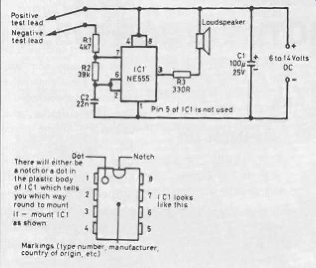
Figure 1 The circuit diagram
Construction
The simplest way to mount the components is on a piece of matrix board (Veroboard), available from any of the good suppliers. The prototype of this circuit used the type of board with copper strips along the underside; these strips are used like the copper tracks on a PCB, to join components together.
Firstly, cut the four strips between the positions of the pins of the IC socket, as shown in Figure 2. You can buy a tool for this purpose, but a small twist drill (about 3mm diameter) is just as good. Turn it between your fingers - if you use a drill you will end up with holes right through the board! Then solder in the IC socket (with the notch in the position shown), followed by the four links made with single-conductor insulated wire. Put in each component as shown, ensuring that C1 (an electrolytic or polarized capacitor) is connected correctly. When all the components have been soldered in, take the 555 chip and lay it on its socket, with its own notch lying above that of the holder. Then, making sure that each pin lies directly above its corresponding socket, press down gently on the chip, with the board supported on a flat surface.
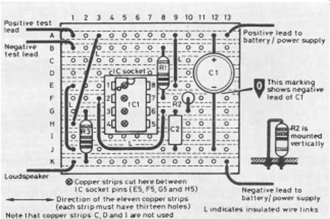
Figure 2 Veroboard layout.
If you can read a circuit diagram, the project can be built using other methods
Testing
Connect the circuit to a battery or small power supply, ensuring that the positive and negative leads are the right way round. Always use red and black leads here, then you are less likely to get it wrong! Switch on. Nothing 19 should happen until you short together the two test leads, when there should be a note from the loudspeaker. If this doesn't happen, switch off, disconnect the circuit and check your wiring and soldering. Is it exactly like Figure 2? Are the soldered joints round and shiny? If any are dull, then 'sweat' them briefly with a hot soldering iron until the solder runs, remove the iron, and check that they are as shiny as the rest. Check that there are no solder 'bridges' between adjacent tracks by holding your board up to a strong light. Then, reconnect, switch on and touch the test leads together.
All should now work!
Uses of your circuit
1. As a Morse practice oscillator. Simply connect the two test leads to your key and, each time the key is pressed, you should hear a note from the speaker. The frequency of the note may be altered by putting a resistor in series with the key. To do this, remove one test lead from the key and select a resistor; connect one end of the resistor to the free test lead and the other to the empty terminal on your key. Selecting the value of resistor that you need will be a useful experiment in itself.
2. As a continuity tester. You can check fuses and lamp bulbs by connecting them across your test leads. If the speaker remains silent, the fuse or bulb has blown.
3. To indicate changes of resistance. Hold the ends of the test leads in each hand; you should hear a low note, because of the high resistance of your body. Squeeze the ends harder, and the frequency of the note should rise, because you are now making better contact. Repeat this with damp hands and the frequencies will be higher still.
4. As a thermometer. Connect the test leads to a thermistor (a device whose resistance changes with temperature) and warm it with a hair-dryer, or even in your hands, and you will hear the pitch changing with the temperature of the thermistor. A suitable 'bead' thermistor is available from Maplin (order code FX21).
5. As a diode tester. Use any diode, and connect the negative test lead to the end of the diode marked with the ring. This is the cathode of the diode.
The other end, the anode, should be connected to the positive test lead, and a note should be heard from the speaker. This does not necessarily mean that the diode is working -- yet. Reverse the connections and nothing should be heard. If this is the case, the diode is working.
6. As a light meter. Use a photoconductive cell (a device whose resistance changes with light intensity) connected between the test leads. A note should be heard. Shading the device with your hand will increase its resistance and the note should decrease in frequency. A suitable device is the ORP12 cell from Maplin (order code HB10).
There are many more applications. Do not connect the test leads to other circuits that are switched on. Your circuit, or the circuit you are connecting it to could be damaged. Think of a passive device or circuit (i.e. one not requiring a power supply or battery) where changes of resistance occur, and you have found another application!
Parts list
Resistors: all 0.25 watt carbon film types
R1 4.7 kilohms (kΩ) - yellow, violet, red
R2 39 kilohms (kΩ) - orange, white, orange
R3 330 ohms (Ω) - orange, orange, brown
Capacitors
C1 100 microfarads (uF) 25V radial electrolytic
C2 22 nanofarads (nF) or 0.022 microfarad (uF) polyester type with 10mm lead spacing
Integrated circuit
IC1 NE555
Additional items
Miniature loudspeaker (preferably 35, 40 or 80 ohm)
8-pin DIL socket for IC1
0.1 inch Veroboard ('stripboard'), size 11 strips by 13 holes
PVC-covered stranded wire for test leads, loudspeaker and battery connections
PVC-covered solid wire for links on the board
A power source of between 6V and 14V, such as a 9V battery (PP3)