AMAZON multi-meters discounts AMAZON oscilloscope discounts
Introduction
A metronome is a device used by musicians to indicate the tempo of a piece of music. Until electronics came on the scene, this 'beating of time' was achieved in much the same way as a clock keeps time, i.e. with a pendulum device, the clicking of the escapement indicating the beats of the music.
Those of you who have already built the Morse Key and Buzzer from the designs in this guide, will recognize the circuit of this metronome -- it is exactly the same as was used to produce the note of the buzzer. This circuit is shown in Figure 1.
The circuit
Three components determine the speed at which the circuit oscillates -- the speaker (LS), the resistors (VR1 + R1) and the capacitor (C1). VR1 is a variable resistor, so that the speed at which the oscillator operates can be varied. Compared with the component values of the Morse Buzzer (which operated at around 800Hz), these components now give an oscillation frequency of around 1.25Hz, which is far too low to be heard as a note.
What we do hear, however, is a series of clicks, as the voltage across the speaker changes quickly from 0 to 9V and back again.
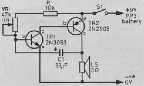
Figure 1 The metronome circuit is rather like the Morse oscillator
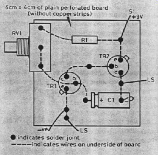
Figure 2 The component wires are pushed through holes in the circuit board
and joined together underneath
Variation of speed could be achieved by varying resistance or capacitance.
However, as you may already know, variable capacitors have values in the picofarad range, not the tens of microfarads used here, so it is very simple to employ a variable resistor (potentiometer) to control the oscillator. You could use a multi-way switch to switch in one of several capacitors, as well as having the variable resistor, but this was found to be an unnecessary complication. This design operates between about 100 clicks per minute and 200 clicks per minute.
Making the prototype
A single piece of plain matrix board (no copper strips) measuring about 40 × 40mm is sufficient to hold all the components except the potentiometer and switch (see later). The case can be plastic or aluminum, and one measuring 65 × 100 × 50mm is about right. Make sure there are holes in the case beside the speaker cone to let the sound out, and larger holes for the potentiometer and switch. If a potentiometer is used with a combined ON/OFF switch, then the extra hole for the switch is not necessary! It is advisable to construct the circuit before putting it in the box, so that it can be tested to ensure that everything is working. If it is, then you can exercise your ingenuity in mounting the speaker, battery and board inside the box. A final test can be made before starting the calibration process.
Calibration
There is no 'easy' way to do this. The frequencies involved are too low to be measured with the average frequency counter, so you will need to resort to using a stopwatch and counting the number of clicks per minute.
Parts list
Resistors: 0.25 watt, 5% tolerance
R1 10 kilohms (kΩ)
VR1 47 kilohms (kΩ) linear potentiometer
Capacitor:
C1 33 microfarads (uF) electrolytic
Transistors:
TR1 2N3053 npn
TR2 2N2905 pnp
Additional items:
S1 SPST ON/OFF switch LS
3 ohms (Ω) loudspeaker
Knob with pointer for VR1
PP3 battery and connector
Aluminum case, 65 × 100 × 50mm
Matrix board (plain), 40 × 40mm