AMAZON multi-meters discounts AMAZON oscilloscope discounts
This section deals with how to make measurements with a multitester, whether it is with an analog meter as described in Section 1 or with a digital meter described in Section 2. However, before discussing the actual measurements, it might be beneficial to review three basic fundamentals of DC circuits. They are: Ohm's law, series and parallel circuits, and polarity.
OHM'S LAW
In the early eighteen hundreds, a German physicist by the name of Georg Simon Ohm discovered the basic relationship of voltage, current and resistance in a DC circuit which he expressed as I=~
Stated in words, it said that the current I in a DC circuit varied directly with the voltage V applied to the circuit and inversely with the resistance R in the circuit. With a given resistance, if voltage is increased, current will increase; with a given voltage, if resistance is increased, current will decrease.
SERIES CIRCUITS
In a series circuit like the one shown in Figure 3-1, there is only one current path.
As shown, the conventional current direction through the circuit is from the positive terminal of the battery to the negative terminal. Electron current is opposite, the negatively charged electrons are attracted to the positive terminal of the battery and released from the negative terminal.
The amount of current in the series current can be found by dividing the voltage (10 volts) by the total resistance in the circuit (100 ohms) just like Ohm's law says:
I= 10V /100 ohm= 0.1A
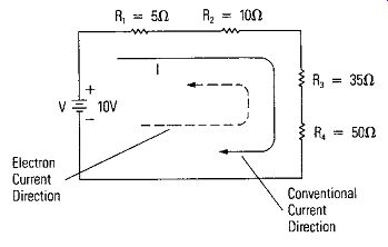
Figure 3-1. Simple DC Series Circuit
The current is 0.1 amperes. There is the same current throughout the series circuit and through each series circuit component. The current has one path through all the circuit components in series.
PARALLEL CIRCUITS
Parallel circuits are different. Current in a parallel circuit has more than one path. The different paths are called branches. Figure 3-2 is a simple parallel circuit. As with the series circuit, it has a 10 volt battery to supply the current, but the current is through two branches - one through R, and the other through R,. The total current IT from the battery divides into the two branch currents, I, and I,. The total current IT is the sum of the two branch currents.
Therefore, IT = I, + I,
Each branch current can be calculated by using Ohm's law. For example, 10V I, = 100 ohm = 0. 1A and 10V I, = 4000 = 0. 025A
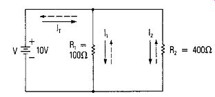
Figure 3-2. Simple Parallel Circuit
The total current is IT= 0.1A + 0.025A I, = 0.125A
One tenth ampere is in the R, branch through R,; 25 hundredths of an ampere is in the R, branch through R,. The total current of 0.125A can also be expressed as 125 x 10 " amperes. The common abbreviation of "milli" is substituted for 10-'; therefore, the current is 125 milliamperes. 100 milliamperes is in the R, branch and 25 milliamperes is in the R, branch.
Note that the voltage across each branch is the same. That is a common characteristic of parallel circuits, the voltage is the same across parallel branches.
POLARITY
When making DC measurements with your multimeter or multitester, you will be concerned about observing polarity so that your meter will read correctly. Current must be in the proper direction through a DC meter to cause it to read up scale. If polarity is observed properly, then the meter will read up scale. Otherwise, the meter will peg against the stop that restricts it from deflecting down scale. Digital voltmeters do not have this restriction; they display the polarity of the voltage, but the reference point for the measurement is still very important.
Reference Point A reference point is a point in a circuit to which the voltage at other points in the circuit is compared. This is demonstrated best by an example. Figure 3-3 combines a pictorial and schematic of the common electrical system for starting your car. The negative terminal of the battery is connected to the automobile chassis which becomes a connecting link of the circuit. It is like a common wire connecting all points marked "chassis ground." This becomes an excellent reference point for all measurements in this automotive circuit. As shown in Figure 3-3, the common or negative terminal of a VOM is connected to the negative terminal (A) of the battery through chassis ground (A'). A voltage measurement is made at point B to measure the battery voltage by placing the positive probe of the meter on point B. The meter reads up scale + 12 volts. Point B is 12 volts positive with respect to the reference point (chassis ground- the negative terminal of the battery). Here are the other voltages in the circuit with respect to the reference point (keeping the common(-) probe of the meter on chassis ground):
Point Meter Reading Comment
A{A'} ov C ov
When ignition switch is OFF C + 12V
When ignition switch is ON D 0V E ov
When ignition switch is OFF E + 12V
When ignition switch is ON
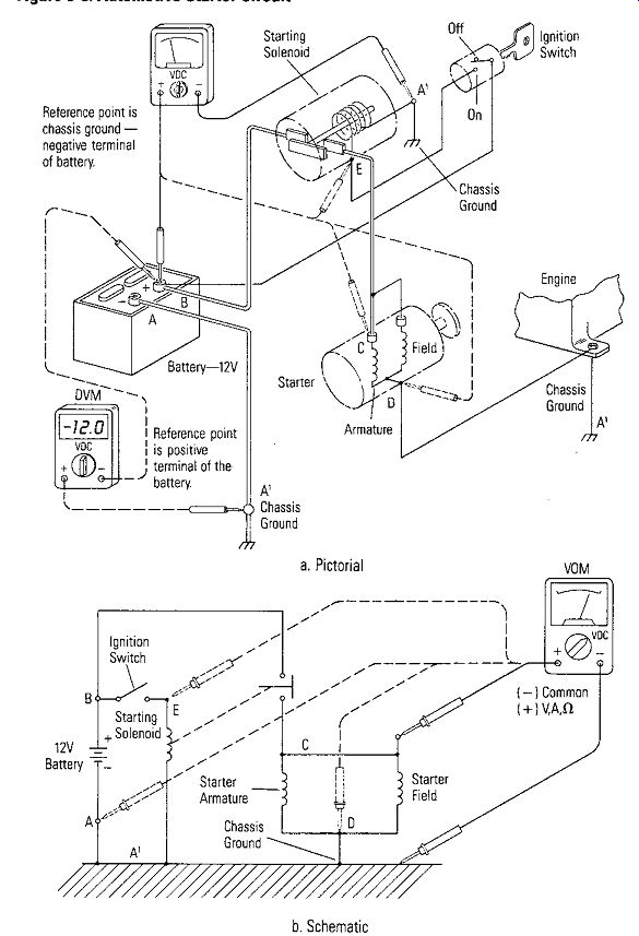
Figure 3-3. Automotive Starter Circuit ---- a. Pictorial --- b. Schematic
Note that when a voltage measurement is made the meter is across two points. In all cases above, all points are a positive voltage with respect to the reference point, or else they have the same potential as the reference point (the voltage is 0 volts). Other reference points could have been chosen. Figure 3-3a also shows the case when the common probe (-) of a D VM is connected to the + terminal of the battery.
Now the measured voltages at the various points (moving the + probe) are:
Point Meter Reading Comment
A(A') -12V B ov C -12V
When ignition switch is OFF C ov
When ignition switch is ON D -12V E -12V
When ignition switch is OFF E 0v
When ignition switch is ON
Note that the negative terminal of the battery, which is connected to chassis ground has a polarity of -12 volts, and the polarity of point D is -12V instead of 0 volts when the reference point was the negative terminal of the battery. So the polarity of a point in the circuit depends on the point chosen for the reference point.
Polarity of Voltage Drops
One other main point on polarity relates to the polarity of voltage drops across components in a circuit. Refer to Figure 34 where three resistors are in a series circuit with a battery. The voltage drops across the resistors add together to equal the battery voltage. The end of the resistor closest to the positive terminal of the battery will be positive while the end closest to the negative terminal of the battery will be negative.
If a DVM is connected with its common probe at point D, the intersection of R, and R,;, then the voltage read across R, will be a positive voltage (point A), and the voltage read across R, + R, (point B) will be a positive voltage. However, the voltage read across R3 (point C) will be a negative voltage because of the polarity of the voltage drop across R, and the fact that point D is the reference point.
If the common probe of the DVM is moved to point A, it becomes the reference point, and the polarity of voltage readings are:
Point
B D C Voltage Drop VR1 is positive VAz is negative V R3 is negative
With this review of Ohm's law, series and parallel circuits and polarity, let's move on to look at multitester measurements.
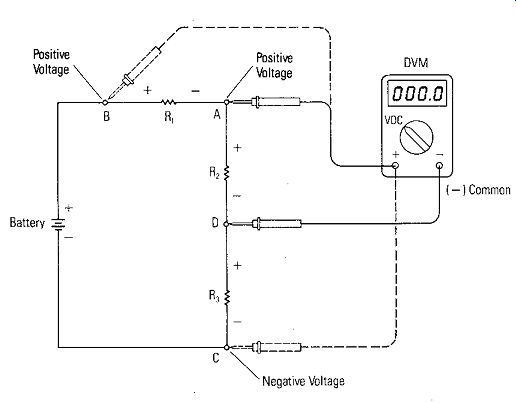
Figure 3-4. Polarity of Voltage Drops
METER LDADING
Meter loading can affect voltage measurements and cause inaccurate readings. The concept of meter loading is explained best by looking at an example illustrated in Figure 3-5. In Figure 3-5a a VOM is used to measure the voltage across R, in a simple DC series circuit which is supplied current by the voltage V. Notice that to make the voltage measurement you must place the voltmeter across resistor R,. The common(-) probe of the meter is at point A and the (+)probe of the meter is at point B. The VOM is represented by a resistor in series with a meter movement. The value of the combination is equal to the input impedance (resistance) of the meter.
Meter Forms Parallel Branch
As shown in the equivalent circuit of Figure 3-5b, placing the VOM across R, forms a parallel branch of the circuit with R,. It adds another path through RM for current besides the path through R,. It means that IT increases because now I,- equals I, plus I, rather than just I, without the meter present. How large will I, be? As discussed in Section 1, if the voltage drop is large enough across R, to cause a full scale VOM reading on the meter range chosen, the current I, through RM will be equal to the current required to deflect the meter movement to full scale.
RM in parallel with R, reduces the equivalent circuit resistance represented by the parallel branch, and produces a corresponding error in the voltage across R,. Let's demonstrate with actual values.
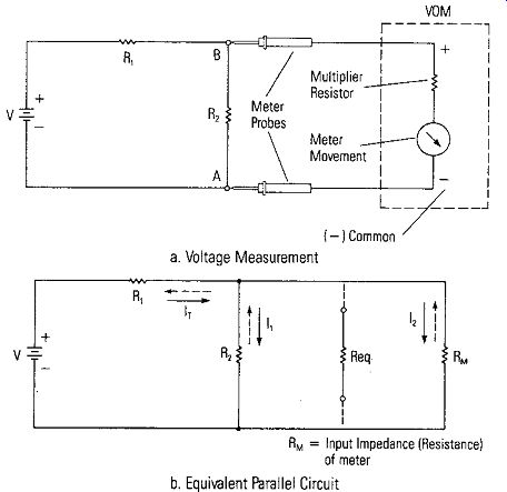
Figure 3-5. Meter Loading When Making Voltage Measurements -------- a. Voltage
Measurement -------- b. Equiv Parallel Circuit
Measurement Error
The equivalent resistance of the parallel branch is R R,RM eq=R,+RM
Let's assume the normal circuit values are: V = 10V R, = 1kO R2 = 1kO
Without the voltmeter measurement, using Ohm's law the total current IT and the voltage drops across R, and R, can be calculated as follows: RT = 2k ohm 10V h = ZkO = 5mA VR, = 1kO x 5mA = 5V Viu = 1kO x 5mA = 5V
Therefore, if a voltage measurement is made without error, the voltage across R, would equal 5 volts.
• Measuring with a 200 Ohms/Volt Meter
Suppose a voltage measurement is made using a VOM that has an internal impedance of 200 ohms per volt, and a full scale range of 5 volts is used. As a result, RM = 5V x 200 ohms/v = 1000 ohms Making the voltage measurement with this VOM makes an equivalent circuit like that shown in Figure 3-6a.
Req can be calculated from equation above as:
JkD x lkD Req = 2kf1 = 0. 5kf1
As shown in Figure 3-6, RT = 1.5kH IT = 6.67mA VR, = 6.67V VR, = 3.33V
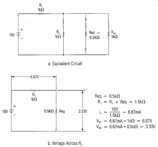
Figure 3-6. Voltage Across R2 When Measured with a 200 Ohm/Volt Meter
The voltage measured across R, ( which is really Req because of the parallel RM) is 3. 33\1, and the percent error in the measurement is:
m E 5.00V - 3.33V lOO ,o rror = 5_ 00 x m E 1.67 100 w rror = 5_ 00 x
% Error= 33%
Making the measurement with a 200 ohms/volt meter has caused the measurement to be in error by 33%.
Measuring With 1000, 2000, and 20,000 VO Ms, Table 3-1 lists the circuit values and errors when the measurement is made on the 5 volt scale. The input impedances are 5000, 10,000, and 100,000 ohms.
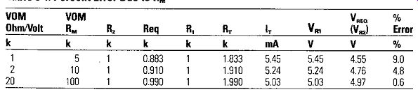
Table 3-1. Percent Error Due to RM
When RM equals 5 kilohms the voltage measurement is still in error by 9%. Not until a VOM is used that has an internal impedance RM of 10 kilohms (10 times the value of R,, the resistance across which the voltage is measured) does the error (4.8%) come down into the range of measurement error of the VOM itself (usually 2% to 4%).
Therefore, to prevent meter loading on a voltage measurement, make sure the input impedance ( resistance) of the voltmeter used for measurement is at least 10 times the impedance ( resistance) across which the measurement is made.
Accuracy Compromise
The value of RM, the VOM input impedance, increases as the voltage full-scale range is increased. A 1000 ohm per volt meter will have an RM = 10,000 ohms on the 10 volt scale and an RM = 50, 000 ohms on the 50 volt scale. To have RM large so it does not load the circuit, the full-scale range should be large so the loading error is small. However, to have the greatest reading accuracy, the full-scale range should be as small as possible to make the meter deflection as close to full scale as possible. These are contradictory statements, so the choice of which full-scale range to use is a compromise when the loading of RM is going to cause significant error.
Measurement with a DVM
As explained in Section 2, electronic circuitry is used in a digital voltmeter. As a result, the input impedance is quite high, usually 1 megohm (one million ohms). Therefore, normal voltage measurements across components that have as high a resistance value as 100,000 ohms will have little or no error. This is one of the significant advantages of using a DVM, little circuit loading occurs unless resistances approach megohm values.
BASIC DC MEASUREMENTS
A typical VOM is shown in Figure 3-7. It is an instrument that is easy to use and simple to operate; therefore, it is very popular with the handyman or the beginner in electricity and electronics. It functions as a voltmeter, ammeter, or ohmmeter depending on the position of a selector switch_ It has 43 ranges -12 for DC voltage from 0 -1000 volts, 8 for ac voltages from 0 - 1000 volts, 10 for DC current up to a maximum of 10 amperes, and 5 resistance ranges to measure resistance from 0 to 20 megohms (20 x l(J-B ohms). A special switch doubles the number of ranges on DC voltage and current and ac voltage by cutting the full-scale of each range in half to provide extra resolution and higher accuracy in the reading. The sensitivity of this meter is 50,000 ohms per volt. That means that the meter movement deflects to full scale with just 20 microamperes (0. 00002A) of current.
Making a VOM DC Voltage Measurement
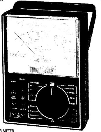
Figure 3-7. VOM --- a. Circuit --- b. Scale Readings
To make a voltage measurement follow these steps. The voltage to be measured is the voltage across R, in Figure 3-8.
1. To prevent an error being introduced, the zero of the meter should be checked before any measurement is made. With a VOM, the instrument should be off and the pointer zero position adjusted mechanically with the zero adjust screw as described in the instrument manual.
2. Set the range selector switch to the DC voltage range desired. It usually is best to start with a range greater than the final one. If you do not know the approximate value of the voltage, place the selector switch on the highest range.
3. Turn on power. Place the minus (-) meter probe at point A. Now touch the plus ( +) probe momentarily to point B. Watch the meter needle and see if it moves up scale. If no movement is detected, rotate the range switch to the next lowest scale until a deflection is noted.
4. If the deflection is up scale, hold the plus probe to point B permanently. (If your test probes have clips on them, clip the leads in place.)
5. If the deflection is down scale (below zero) reverse the leads or, if the meter has a +/- polarity switch, switch the polarity so that the deflection is up scale.
6. Rotate the selector switch to get the greatest on-scale needle deflection without exceeding full scale. In the example of Figure 3-8, the voltage is 4 volts; therefore, the selector switch would be set on 10 volts and the meter would read 4 on the 10 volts scale as shown in Figure3-8b. The 2.5 volt scale of the VOM of Figure3-7 would cause the meter to go beyond full scale.
7. The meter of Figure 3-7has a switch that reduces the range selected in half.
Switching the switch to V/2 reduces the full-scale range to 5 volts and the needle would now read 4 volts as shown in the dotted line position of Figure 3-Bb. (The actual reading is taken using the 50 volt scale and, because the range selector is on the 5 volt range, every meter reading is divided by 10.) This provides a deflection closer to full scale, and thus, a more accurate reading.
8. Parallax is reduced by aligning the needle with the image in the mirror above the DC voltage scales.
9. If the battery voltage is to be measured, the plus probe would be momentarily touched to point C of Figure 3-8a with the range selector switch on the 50 volt range. Steps 4 through 8 would then be followed to read 12 volts on the 25 volt range.
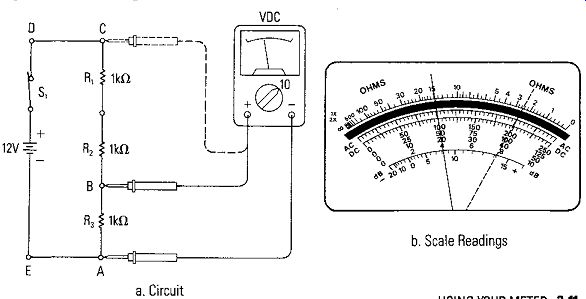
Figure 3-8. DC Voltage Measurement
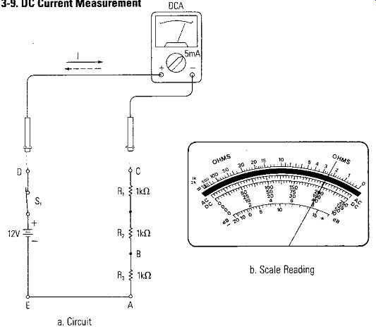
Figure 3-9. DC Current Measurement
Making a VOM DC Current Measurement
Current measurements are different. The meter must be inserted into the circuit so that the circuit current is through the ammeter. Figure 3-9 shows a VOM used as an ammeter inserted in the series circuit of Figure 3-8 to measure the series circuit current. The steps to be followed for this measurement are as follows:
1. With the meter out of the circuit, check the zero position of the meter and mechanically adjust it with the zero adjust screw if required.
2. Turn off the circuit power and disconnect the circuit so that the meter may be inserted. In Figure 3-9, point C is disconnected from the battery terminal at point D and the ammeter inserted.
3. Set the range selector switch to the highest DC current range. Some VOMs will have a function switch so that volts or amperes or ohms may have to be selected as well as the range. If so, the amperes function would be selected.
4. Place the plus probe of the meter at the most positive voltage point (point D) and the minus probe at the more negative voltage point (point C). The direction of current is as shown.
5. Turn on power. Touch the terminal C momentarily to see that the meter needle deflects up scale when power is on. If deflection is down scale, reverse the meter leads.
6. After power is on, adjust the selector switch to give the greatest on-scale deflection. Since the current in Figure 3-9 is 4 milliamperes, the range selector would be set on 5 milliamperes full scale, and the needle would read 4 milliamperes as shown in Figure 3-9b (as with the voltage measurement, the 50 scale is used and all readings divided by 10). There is no need to use the half-scale function switch in this case.
Be aware that the highest current range is 10 amperes. However, the plus ( +) lead must be plugged into an auxiliary jack to activate the 10A current range.
Making a VOM Resistance Measurement
Complete information on the condition of electrical circuits and the circuit components cannot be obtained by the use of the voltmeter and the ammeter alone. Using an ohmmeter adds significantly to your information about a circuit. Knowing for sure that a circuit is complete (there is continuity) and being able to measure the resistance of the various circuit components are valuable pieces of circuit information obtained by using an ohmmeter.
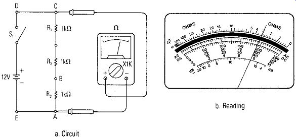
Figure 3-10. Resistance Measurement
Recall that a VOM when used as an ohmmeter supplies its own current from an internal power source (either 1 or 2 batteries) to operate the meter movement. All circuit power is to be turned off or removed when making continuity and resistance measurements, otherwise there is danger of damaging or completely burning out the VOM.
• Example Measurement
The meter of Figure 3-7uses a series circuit for the ohmmeter. As a result, zero on the resistance scale is full-scale deflection, and open circuit or "infinity" ohms is the idle position of the needle. We will measure the resistance of the circuit of Figure 3-8 as shown in Figure 3-12. Follow these steps:
1. Make sure power is disconnected from the circuit.
2. Make sure the VOM is on the ohmmeter function, either by the position of the range selector switch or by a function switch that selects the ohmmeter function or both.
3. Short the meter leads together and with the OHMS ADJUST control, adjust the meter reading to 0 ohms. If this adjustment cannot be made, the battery internal in the meter needs to be replaced.
4. Place the meter leads across the resistance to be measured. For example, point A and point C in Figure3-10.
5. Change the range selector switch to cause the meter reading to be between half-scale and full-scale if possible, or as close to half-scale as possible. If the meter reading is close to the high resistance end of the scale, select a higher resistance range; if the reading is closer to the low resistance end, select a lower resistance range. Of course with very high resistances, the meter reading will always be to the left (high resistance end) of the scale.
6. Since the resistance in this case is 3 kilohms, the range selector would end up on the R x 1K range and the meter would read 3 as shown in Figure 3-10b. The range switch selects different values that multiply the meter reading. On the R x 1 scale, the meter reading is taken directly. On the R x 10 K all readings are multiplied by 10,000. When making in-circuit measurements, remember that circuit paths in parallel with the component being measured may cause reading errors. Check the circuit diagram for the presence of such parallel paths before assuming that the reading obtained is correct.
• VOM Resistance Measurement Accuracy
The accuracy of a VOM in making resistance measurements is slightly different from its accuracy in making voltage and current measurements. The percent of accuracy of an ohmmeter at center scale is specified as a percentage of the complete arc made by the needle when reading resistances from 0 to infinity. A typical accuracy is 2% of arc. To maintain this accuracy, it is most important that the idle position of the needle be set on the end of scale mark with the mechanical screw adjustment and that the full-scale adjustment be set on the end of scale mark with the OHMS ADJUST control.
DVM DC Voltage Measurements
A digital multimeter like the one shown in Figure 3-11 is chosen for our example measurements. Two significant differences are apparent between this DVM and a VOM. First, the output is a digital display where the meter reading is a particular number.
Second, since electronic circuits are required to produce the conversion required, power must be supplied to the electronic circuits; therefore, the DVM has a power switch which must be ON for all measurements.
As shown in Figure 3-11, beyond these differences, functionally the DVM and VOM are very similar. A range selector switch selects the function and the range, the meter leads are plugged into a common (-) jack and a plus (+) jack to make measurements, or the plus lead is plugged into special auxiliary jacks for special current ranges (2A and 200mA).
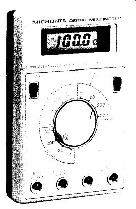
Figure 3-11. DVM Used for Example Measurements
The steps for making a voltage measurement with a DVM using the circuit of Figure 3-8 are basically the same as they are when a VOM is used. The exceptions are that no zero adjustments or polarity precautions are necessary because the meter takes care of these automatically. The actual reading will be a number on the digital display. For example, the four volt measurements of Figure 3-8 would read 4.00 on the 20 volt range, if it is exactly four volts; otherwise, it will read some fractional voltage to two decimal places.
• Polarity
Test leads need not be switched when measuring with a DVM. The display will indicate whether the voltage reading is a positive or negative voltage with respect to the common lead.
• Overrange and Fused Protection
A special indicator also appears on the display to indicate that the reading is over range on the range selected. Change the range selector to the next highest range until a digital reading is obtained or the highest range is reached. The voltage being measured exceeds the highest full-scale reading if an overrange indication is obtained on the highest range.
Many instruments also are fused against excessive current on any range.
• Low Battery Voltage
A special indicator usually is available to indicate when the internal batteries supplying power must be replaced.
DVM DC Current Measurements
The current measurement functionally is the same as the steps outlined for the VOM current measurement, except, as for the voltage measurements, the leads need not be exchanged from wrong polarity, and there is no zero adjustment The 4 milliamperes would read 4. 00 on the 20 milliamperes range, if it is exactly four milliamperes; otherwise, some fractional value to two decimal places will be indicated.
As explained in Section 2, what is actually happening in the current measurement is that a small resistance is inserted in the circuit and the DVM is measuring the small voltage drop across the resistance due to the circuit current.
DVM Resistance Measurements
The same precautions must be followed when measuring resistance with a DVM as with a VOM. Remove power from the circuit before making resistance measurement. The measurement is made with the test leads across the component to be measured. Current from the DVM causes a voltage drop across the component resistance and the voltage is read by the DVM and converted to a direct resistance measurement.
When measuring the resistance of Figure 3-10, the DVM would read 3. 00 on the 20 kilohm range if the resistance is exactly 3000 ohms; otherwise, the reading would be some fractional value to two decimal places.
BASIC AC MEASUREMENTS
Here are some factors that are important when making ac measurements.
1. AC voltage and current measurements depend on frequency. Consult the meter manual to determine the limits of the meter's frequency response.
2. Most VOMs read in rms values, but ac meters can either read average, rms, or true rms values. Only true rms reading meters do not require the ac signal to be a sine wave without producing error.
3. AC current measurements are accomplished by rectifying a voltage developed across a resistor in the circuit.
4. AC VOM readings are accurate to a percent of full-scale, but the accuracy and sensitivity are usually less than for DC measurements.
5. Non-linear rectifier characteristics make small ac voltage measurements less accurate.
6. VOMs usually have more loading effect on the circuit than for DC.
7. On ac measurements, a DVM usually has the same accuracy, sensitivity and circuit loading as it does on DC.
8. When an ac voltage is applied to circuits that only have resistance (such as Figures 3-8 and 3-9), the measurement steps are the same as outlined for DC measurements.
There will be no polarity observance needed because the ac voltage or current is alternating positive and negative with time.
Clamp-On Current Meters
Some VOMs today have a clamp-on accessory that may be used as a clamp-on ammeter for measuring ac currents. This adapter is clamped around a wire carrying a large ac current and the current is then transformed to an ac voltage so that the VOM uses the ac volts function to measure the ac current in the conductor. There may be special scales included on the meter face for the clamp-on adapter so the current can be read directly.
AC Impedance and Reactance
The opposition to current in a dc circuit is termed resistance. If the opposition to current in an ac circuit is due to resistance, the effect is the same; however, if the circuit contains inductors or capacitors, the opposition to ac current is more complex. As discussed previously, inductors are coils of wire wound around iron cores contained in motors, generators, solenoids, relays, chokes, and transformers. Capacitors are the components that store charge on parallel plates separated by a dielectric so there is no DC path through the capacitor. Inductors store energy in magnetic fields; capacitors store energy in electrostatic fields.
Reactance
The opposition offered by an inductor or capacitor is called reactance. The reactance of each of the components is frequency sensitive. Inductive reactance is expressed as XL = 2 pi fL and capacitive reactance is expressed as 1 Xe = 2 pi fC where f is frequency in hertz (cycles per second), L is inductance in henries, C is capacitance in farads, and pi is a constant 3.1416 - - - . The unit for reactance is ohms just like resistance. If f = 0 (which is DC), XL will be zero and Xe will be infinity. If f = x (infinity), XL will be equal to infinity and Xe will be zero.
• Impedance
Impedance is the term given to the total opposition to ac current when both resistance and reactance are present to impede the current. The reactance can be inductive, capacitive or a combination of both. What makes impedance and ac voltage and current complex is that measured quantities do not add directly. They must be added vectorially.
• Vector Addition
How voltage, current and impedance add vectorially is best demonstrated by an example.
Look at Figure 3-12. A 60 cycle 50 volt (rms voltages are identified by VAC) power source is connected to a resistor and solenoid. The resistor has 30 ohms resistance, and the solenoid has 40 ohms inductive reactance. To find the total impedance of the circuit the resistance and reactance must be combined at right angles as shown in Figure 3-12.
The resistance is plotted horizontally and the reactance is plotted 90° upright from it, joined tip to tail and represented by arrows called vectors with appropriate length and to the same scale. The total impedance Z is another vector from the start ( tail) of the resistance to the tip of the reactance. This forms the hypotenuse (the long side) of a right triangle.
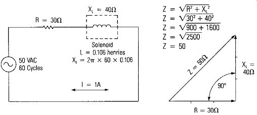
Figure 3-12. Impedance with Rand X,
A mathematical theorem (Pythagorean's Theorem) states that the hypotenuse of a right triangle is equal to the square root of the sum of the squares of the sides. Therefore, the total impedance of the circuit of Figure 3-12 can be calculated as z = V30' + 40" Z = \1900 + 1600 z = \12500 Z = 50 Since Z is the total opposition, the total current in this series circuit can be found by using a form of Ohm's law for ac circuits: or V I= l 50V 1=500. I= 1A
The total current is one ampere.
Ohm's law for ac circuits can now be used to find the voltage across the respective components. The voltage across the resistance is VR = I X R VR = 1A x 30D. VR = 30V
The voltage across the inductance is v, = I XX, V, = 1A x 40D. V, = 40V
Voltage Measurements
If a VOM on an ac voltage range of 50 volts is used to measure the voltage across the resistance and inductance, the voltages measured would be 30 volts across the resistance and 40 volts across the solenoid. If now the source voltage is measured, it would measure 50 volts . .Each of these measurements is shown in Figure 3-13. Note that the voltages across each of the components add directly to 70 volts, but the source voltage is only 50 volts. In circuits where the total impedance is made up of resistance and reactance, the measured voltages must be added vectorially. Figure 3-13 shows how the total voltage of 50 volts is the vectorial sum of the 30 volts across the resistance and 40 volts across the solenoid.
The steps for making the voltage measurements are basically the same as for dc.
Summarized they are:
1. With leads open, adjust the zero reading of the meter with the mechanical zero adjust, if available.
2. Set the function selector switch to the highest ac voltage range.
3. Measure voltage; adjust voltage range downward to get a meter reading as close to full-scale as possible.
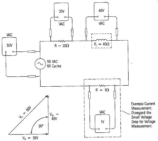
Figure 3-13. Voltage Measurements of Figure 3-12 Circuit ----- Example
Current Measurement. Disregard the Small Voltage Drop for Voltage Measurement.
Current Measurements
Current measurements are made in ac circuits by using the current function on the selector switch and inserting the meter leads into the circuit just as with DC current measurements. If your meter does not have an ac current function, current measurements can be made easily by inserting a small known value of resistance into the circuit and measuring the ac voltage across it. An example is shown in the dotted insert of Figure 3-13. The voltage drop across the one ohm resistor used for the current measurements may be disregarded when the voltage measurements are made.
Caution: When making current measurements in ac circuits that contain parallel branches with inductors and capacitors in parallel, very high circulating currents can be encountered in the parallel branches at particular frequencies of the applied voltage.
Impedance Measurements
Even though there are special impedance meters where meter scales are calibrated in ohms impedance, VOMs and DVMs normally do not have impedance scales as they have resistance scales. Impedances are obtained by measuring voltage and current and calculating impedance.
POWER MEASUREMENTS AND CALCULATIONS
Indirect measurement of voltage and current will provide the power being delivered or dissipated in a circuit The power P, using a measured voltage V, and current I is calculated as P = I x V
DC Circuits
In DC circuits the power calculation is a direct one. The power is dissipated as heat.
AC Circuits
In ac circuits, reactance again complicates the power calculation. The multiplication of voltage times current may not result in true dissipated power, but may result in an "apparent" power because of the reactances present. Consult a more detailed text on ac circuits for a more complete understanding of the subject.
SUMMARY
With the description of the meters and how they operate and a basic understanding of measurements, we move on in the next section to some actual practical examples of meter measurements.