AMAZON multi-meters discounts AMAZON oscilloscope discounts
An important part of the field of electronics is understanding the various components and electron devices that make up complex electronic circuits. Every electrical circuit has three inherent properties: resistance, capacitance and inductance. Measuring common components with these properties using a multimeter is the subject of this section.
HOW TO MEASURE A RESISTOR
Resistor Basics -- Fixed and Variable
Resistance in a circuit is the opposition to current. All materials used in an electric circuit will offer some resistance. Those offering low resistance are called conductors and are used as paths for current. Those offering extremely high resistance provide no path for current and are called insulators. Components manufactured specifically to be placed in a circuit to provide resistance are called resistors and are used most frequently in electrical circuits to limit current or to create voltage drops. Insulators are used to resist or prevent current in certain paths.
Resistors come in different values, shapes and sizes. Resistors are classified two ways -- by resistance measured in ohms and by power rating measured in watts. The power rating of resistors for electronic circuits range from 1/8 watt to hundreds of watts. The ohmic values range from hundredths of ohms (0.01) to hundreds of megohms (100 x 10^6). Manufacturers have adopted a standard color code system for indicating the resistance or ohmic value of low power resistors (normally below 2 watts). Higher power resistors usually have the resistance value imprinted on their bodies. An assortment of different types of resistors with different wattage ratings are shown in Figure 4-1.
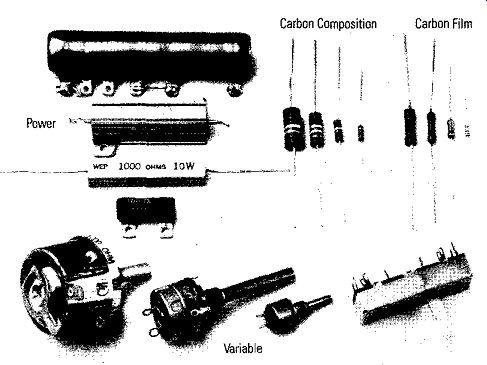
Figure 4-1. Different Type Resistors Carbon Composition Carbon Film
Construction
The small wattage rating resistors (also physically small) are usually carbon composition or deposited carbon. The carbon composition resistors are made of finely ground carbon mixed with a binder molded to a shape with pigtail leads. The compressed mixture can be made to have a resistance from one ohm to tens of megohms. This type resistor usually has wattage ratings of 2 watts or less, and the resistance value is indicated by color coded bands encircling the body of the resistor.
The deposited carbon resistor consists of carbon vapor deposited on a glass or ceramic form. Spiral paths are etched into the carbon until the desired resistance is obtained. Such resistors are usually higher precision types (value is accurate to 1% or less). Wirewound resistors of different wattage ratings also are shown in Figure 4-1.
They are made of resistance wire wound on a ceramic core. Fusible resistors are a special type of wirewound resistor made to burn out and open the circuit to protect other components if current becomes greater than the fuse resistor is designed to handle.
Figure 4-1 also shows two types of variable resistors. A variable resistor is either carbon or wirewound with a movable wiper arm that ¼ill contact the resistance element at any point between the end extremes. When the arm is moved, usually with a shaft, the resistance between the wiper arm and either end varies. These variable resistors are commonly called potentiometers or rheostats. If three terminals are used in the circuit, it is referred to as a potentiometer. If only two terminals are used, it is referred to as a rheostat.
Color Codes
Resistor values are measured in ohms with an ohmmeter. As shown in Figure 4-2, a common way of indicating resistance values for composition resistors is to use color bands on the body of the resistor. A standard color code for the bands has been adopted by resistor manufacturers, and the numerical values they represent are given in Table 4-1. Figure 4-2 shows how to evaluate the bands. The first band will be nearer one end of the resistor. Read from this band toward the other end. The first band is the first significant number; the second band, the second significant number; and the third band, the multiplier (number of zeros that follow the first two numbers) to indicate the resistor's value. If the third band is gold or silver, this would indicate a multiplier of 0.1 or 0. 01, respectively, rather than additional zeros.
As the resistors are manufactured they all will not be exactly the same value.
The fourth band indicates the tolerance of the resistor's value from the indicated (color code) value. A gold fourth band indicates ± 5%, a silver band ± 10%, and no fourth band indicates a tolerance of ± 20%. The resistor's value will be within a tolerance band of ± 5%, ± 10%, or ± 20% of the color coded value.
The resistor in Figure 4-2 is a 27,000 ohm or 27 kilohm resistor with a ± 10% tolerance. The value of the resistor can be anywhere from 24,300 ohms to 29,700 ohms. As shown in Figure 4-1, its physical size indicates the power rating.
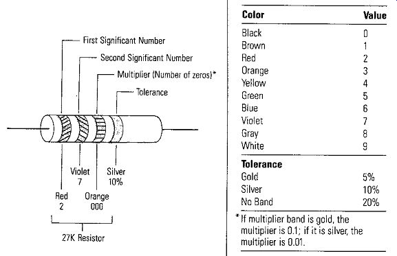
Figure 4-2. Color Bands Indicating Resistance;
Table 4-1. Resistor Color Code
• If multiplier band is gold, the multiplier is 0.1; if it is silver, the multiplier is 0.01.
Measuring a Fixed Resistor
• Out of Circuit
One of the easiest measurements to make with a VOM is to measure the value of a fixed resistor out of a circuit. Use the VOM as an ohmmeter and connect the test leads of the ohmmeter across the resistor as shown in Figure 4-3.
• In Circuit
Recall from Section 1 the two precautions that must be observed when using an ohmmeter to measure a resistance in a circuit:
1. The power source must be turned off. Disconnect the equipment from the power source, if possible.
2. When the resistor is in a circuit, if possible, disconnect one end of the resistor from any circuit or additional component so only the resistance of the single resistor is measured.
Figure 4-4 shows the correct way to measure the resistance of R,. Notice the supply Vs has been disconnected. Also, note that one end of R3 is disconnected from the circuit so the ohmmeter measures the resistance of R, alone. If R, is not disconnected, then the value of resistance measured would be R, in parallel with R,.
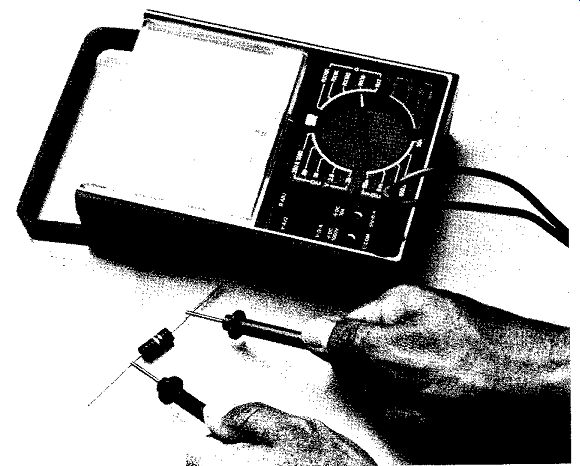
Figure 4-3. Measuring a Resistor Out of a Circuit
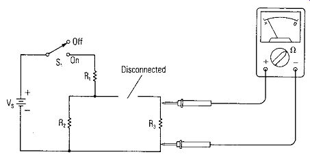
Figure 4-4. Measuring a Resistor in a Circuit
Measuring a Variable Resistor
When a potentiometer is checked with an ohmmeter, the total resistance is first measured from end-to-end as shown for point A in Figure 4-5. The reading typically may be within a tolerance of ±20% of the stated value. Next, the resistance should be tested from the wiper arm to one end as the potentiometer is rotated through its full range as shown for Point B in Figure 4-5. The resistance should vary smoothly from near zero to the full value of the resistance. Since the reading should vary smoothly and continuously, this is one place where a VOM has the edge on the DVM. Any sudden jump to either a higher or lower value, or any erratic reading would indicate a defective spot on the resistance element. If the wiper arm is not making firm contact with the resistance element, simply tapping the case of the potentiometer may produce erratic resistance readings. Any of these erratic indications mean a defective or dirty potentiometer. A spray cleaner may salvage the unit; however, if after cleaning it does not produce a smooth resistance change over its entire range, it should be discarded.
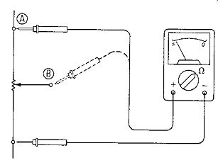
Figure 4-5. Measuring a Variable Resistor
Rheostats may be tested by a similar process with the exception that the only measurement is from the wiper to one end since the rheostat only has two terminals.
In general, rheostats will be open if they are defective because they usually are high wattage units and must handle high current.
Thermally Intermittent Resistors
All electronic components, including fixed and variable resistors, can be thermally intermittent. Measure the resistance while subjecting the suspected component to extreme temperature change to detect this type of defect. Radio Shack stores stock an aerosol spray component cooler to spray on a resistor to cool it. The tip of the soldering iron can be used to heat it. Be careful not to apply such an excessive heat to damage the resistor. A sudden or erratic change in resistance as temperature is changed indicates the resistor is thermally intermittent and defective.
"Shifty" Resistors
There is a class of resistors whose resistances change as the operating conditions change. Common ones are thermistors, varistors, and photoconductors.
Thermistors and photoconductors can be measured with an ohmmeter. The resistance of a varistor is calculated from voltage and current measurements.
• Thermistors
A thermistor is a resistor whose resistance varies with temperature. It exhibits large negative temperature characteristics; that is, the resistance decreases as the temperature rises and increases as the temperature falls.
• Varistors
A varistor is a resistor whose resistance is voltage dependent. Its resistance decreases as voltage across it is increased.
• Photoconductors
A photo cell's resistance (photoconductor) varies when light shines on it. When the cell is not illuminated, its "dark" resistance may be greater than 100 kilohms. When illuminated, the cell resistance may fall to a few hundred ohms. These values can be measured with an ohmmeter.
HOW TO MEASURE A CAPACITOR
Capacitor Basics
Capacitance is the property whereby two conductors separated by a non-conductor (dielectric material) have the ability to store energy in the form of an electric charge and oppose any change in that charge. The operation of a capacitor depends on the electrostatic field set up between the two oppositely charged parallel plates.
The unit of capacity is the farad, named in honor of Michael Faraday. It is the amount of capacitance which will cause a capacitor to attain a charge of one coulomb when one volt is applied. Expressed as a mathematical equation:
C=~ where C will be one farad when Q is one coulomb and Vis one volt.
The value of capacitance, the farad, is very large for practical applications; therefore, smaller values are used. A microfarad is 10-s farads; a nanofarad is 10·' farads; and a picofarad is 10·" farads. Microfarads and picofarads are very common in electronic circuits.
The physical factors which determine the amount of capacitance a capacitor offers to a circuit are:
a. the type of dielectric material, (K);
b. the area in square meters of the plates, (A);
c. the number of plates, (n); and
d. the spacing of the plates in meters, which also is the thickness of the dielectric, (t).
The basic capacitor and its symbol are shown in Figure 4-6 with the relationship between the physical factors indicated so the amount of capacitance can be calculated. n = 6 in Figure 4-6b, but the most common capacitors have 2 parallel plates.
Caution: Before a capacitor is measured with an ohmmeter, remove it from the circuit and short across its leads or plates to make sure it has no residual charge.
Such residual charge could damage an ohmmeter.
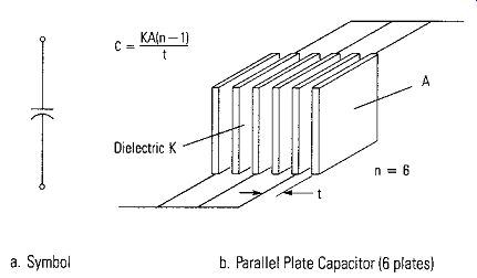
Figure 4-6. Basic Parallel Plate Capacitor -- a. Symbol b. Parallel Plate
Capacitor (6 plates)
Relative Amount of Capacitance
Two capacitors can be compared as to their relative capacitance by using a VOM. The amount of needle deflection of an ohmmeter can be used to indicate a relative amount of capacitance. By connecting the ohmmeter to the capacitor as shown in Figure 4-7 a, the ohmmeter battery charges the capacitor to its voltage. The meter will deflect initially and then fall back to infinity as the capacitor charges. In Figure 4-7b, after the initial charge of the capacitor, the ohmmeter leads are reversed and the capacitor voltage is now in series with the voltage inside the ohmmeter. The charge on the capacitor is aiding the ohmmeter battery. The needle now deflects a larger deflection proportionally to the amount of capacitance, and then decays as the charge is redistributed on the capacitor.
Leaky and Shorted Capacitors
Paper, mica and ceramic capacitors fail in two ways. The dielectric breaks down and the capacitor plates short together, or the capacitor becomes "leaky." When "leaky," the dielectric still supports a voltage but the dielectric resistance becomes much lower than normal. Both of these conditions can be detected with a VOM or DVM. There are two checks that can be made. The first is simply a resistance measurement using the VOM or DVM as an ohmmeter across the terminals of the capacitor. If the capacitor is shorted, the ohmmeter will read zero or a very low value of resistance. If the capacitor has become "leaky," then the resistance measurement will be much less than the normal nearly infinite reading for a good capacitor. Leaky capacitors need to be replaced before they turn into shorted capacitors.
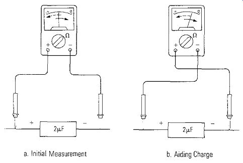
Figure 4-7. Measuring Relative Amount of Capacitance ---- a. Initial Measurement
--- b. Aiding Charge
In some capacitors, the dielectric does not become "leaky" until a voltage is applied, That is, it breaks down under load, This defect cannot be detected with an ohmmeter but can be found by using the VOM or DVM as a voltmeter as shown in Figure 4-8, A DC voltage is placed across the series combination of the voltmeter and the paper, mica, or ceramic capacitor (not for electrolytic capacitors unless proper polarity is maintained). A good capacitor will show only a momentary deflection on the voltmeter, then the reading will decay to zero volts as the capacitor charges to the supply voltage. A defective capacitor ¼ill have a low insulation resistance, R_INS, (it may be at a particular voltage), and will maintain a voltage reading on the meter.
The lower the insulation resistance of the capacitor, the higher the voltmeter will read. When insulation resistance is checked by this method, it is in series with the meter. Because R_INS is normally high, it limits the current; therefore, a change in the VOM voltmeter range does not significantly affect the total resistance of the circuit, and the percentage of meter-scale deflection remains fairly constant with different voltmeter ranges. The power supply voltage V. should be set for the rated working voltage of the capacitor for this test.
If the insulation resistance is such that it produces a scale reading on a VOM or DVM, the R_INS may be calculated by using the following equation:
... where Vs supply voltage VM R_INPUT R_INs VOM or DVM measured voltage VOM or DVM input resistance capacitor insulation resistance
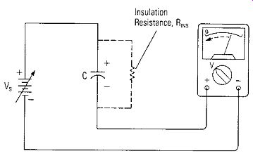
Figure 4-8. Measuring R_INS Using a Voltmeter ---- For R_ins Full scale
range selected for VOM at least equal to Vs For Electrolytic Capacitor Meter
is used as an ammeter
Measuring An Electrolytic Capacitor
Special care must be taken when measuring electrolytic capacitors because they are polarized. As a result, when using a VOM as an ohmmeter to test an electrolytic capacitor, the ohmmeter test lead polarity must be correct to give the proper indication. In most cases, this occurs when the positive ohmmeter test lead is connected to the positive electrolytic capacitor terminal. In any case, the test lead arrangement that gives the highest resistance reading is the one to use.
Leakage Current of Electrolytic Capacitors
Measuring the leakage current of an electrolytic capacitor is the best way to judge whether the capacitor is still useful. The same circuit of Figure 4-8 is used for measuring leakage current of electrolytic capacitors except now the meter is an ammeter. Vs , the capacitor's rated voltage, is applied across the capacitor, and the leakage current is indicated by the series ammeter. The maximum permissible leakage current of a new electrolytic capacitor is related to the voltage rating (WVDC) and capacitance of the capacitor according to the following equation:
I= kC + 0.30 where I = leakage current in ma C = rated value of capacitor in microfarads k = a constant as given in Table 4-2 Many factors affect the amount of leakage, such as, the age of the capacitor, how long it has been uncharged in a circuit, how near its rated voltage it has been working or how long a new one has been on the shelf. If the capacitor exceeds the permissible leakage values, it should be discarded. Experience will help make this test more conclusive.
HOW TO MEASURE INDUCTORS
The property of an electric circuit or component that opposes changes in circuit current is called inductance. The ability of the circuit or component to oppose changes in current is due to its ability to store and release energy that it has stored in a magnetic field. Every circuit has some inherent inductance but devices which purposely introduce inductance to a circuit are called inductors. Let's look at some basics of inductance, and how to test inductors with a VOM or DVM.
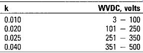
Table 4-2. Electrolytic Capacitor Constant
Inductor Basics - Inductance and Impedance
An inductor may take on any number of physical forms and shapes. However, it is basically nothing more than a coil of wire. Inductors are sometimes referred to by such names as choke, impedance coil, reactor, or combinations such as choke coil or inductive reactor. The amount of inductance of a coil is measured by a unit called the henry. Smaller units, like for capacitors. are practical~ the millihenry (1 x 10-, henries) and microhenry (1 x 10·" henries) are very common units in electronic circuits.
The amount of inductance in an inductor depends on the magnetic flux produced and the current in the coil. Mathematically, this may be expressed by the following equation: L ~ N¢ I where L is the inductance in henries I is the current through the coil in amperes N is the number of turns of wire ¢ is the magnetic flux linking the turns.
Basically all inductors are made by winding a length of conductor around a core which is made either of magnetic material or of insulated material. When a magnetic core is not used, the inductor is said to have an air core. The physical characteristics, or geometry, of both the core and the windings around the core affect the amount of inductance produced. Figure 4-9 illustrates these factors. The more turns, the better the magnetic core material, the larger core cross section area, and the shorter the coil length all increase the inductance.
In a DC circuit, the only changes in current occur when the circuit is closed to start current, and when it is opened to stop current. However, in an ac circuit, the current is continually changing each time the voltage alternates. Since inductance in a circuit opposes a change in current and ac is continually changing, there is an opposition offered by the inductor to the ac current that is called reactance. The amount of inductive reactance is given by the following equation: x, ~ 2 pi fL where XL is the inductive reactance in ohms, f is the frequency of the ac in hertz, L is the inductance in henries.
The quantity 2 pi f represents the rate of change of current in radians per second .. It is called angular velocity.
In ac circuits that contain only inductance, the inductive reactance is the only thing that limits the current. The current is determined by Ohm's law with X, replacing R, as follows:
I ~ _y_ X,.
If an ac circuit contains both resistance and inductance (reactance), then the total opposition to current flow is termed impedance and is designated by the letter Z. When a voltage V is applied to a circuit that has an impedance Z, the current I is I = ¥ ( where Z = YR' + XL' )
Continuity
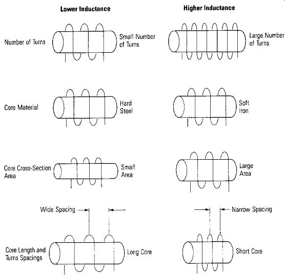
Figure 4-9. Physical Factors That Affect the Value of Inductance ---- Lower
Inductance Higher Inductance
A series RL circuit may be formed by one or more resistors connected in series with one or more coils. Or, since the wire used in any coil has some resistance, a series RL circuit may consist of just a coil or coils by themselves. The resistance of the coils, which effectively is in series with the inductance, supplies the circuit resistance. Using a VOM as an ohmmeter, a simple continuity test will quickly locate an open inductor. The resistance can be measured easily for any inductance that is not open. Just place the meter used as an ohmmeter across the coil terminals and measure the resistance just like a resistor was measured in Figure 4-3. Normal resistance values depend on the wire size and number of turns (length) of the wire that makes up the inductor. Some coils with fine wire and a large number of turns will have hundreds of ohms resistance; large coils with large wire and a small number of turns will have tens of ohms. If no resistance is measured at all, the inductance 1s open.
Other Failures
Inductors become defective because insulation breaks down and turns short together or the coil shorts to the core. Simple continuity checks with an ohmmeter between one end of the coil and the core detect the coil shorted to the core, but a few shorted turns on an inductor are very difficult to detect. If one-half the coil shorts out, resistance checks should detect it, but for a few turns, very accurate measurements must be made in order to detect that the coil is defective.
TRANSFORMER BASICS
As shown in Figure 4-10, a transformer is a device for coupling ac power from a source to a load. A conventional transformer consists of two or more windings on a core that are isolated from each other. Energy is coupled from one winding to another by a changing magnetic field. An ac voltage applied across the primary results in primary current. The changing current sets up an expanding and collapsing magnetic field which cuts the turns of the secondary winding. This changing magnetic field induces an ac voltage in the secondary which produces a current in any load connected across the secondary.
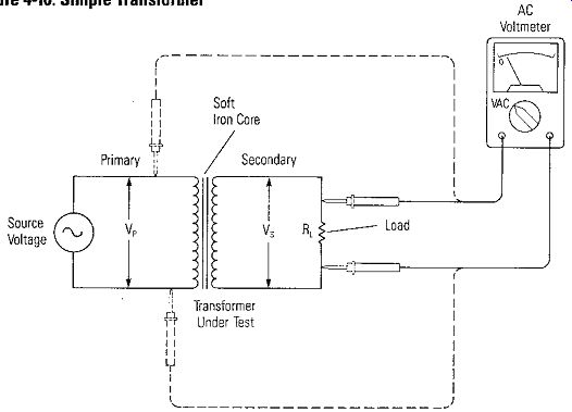
Figure 4-10. Simple Transformer.
The core around which the primary and secondary are wound may be iron for low frequencies, as in the case of power and audio transformers. Primary and secondary windings on an air core may be employed for transformers that couple energy in higher frequency circuits.
Ideal Transformer
If the transformer were ideal, there would be no power loss from primary to secondary and 100% of the source power would be delivered to the load. Since voltage times current equals power, the power relationship is given by:
VP X ]., = Vs X Is where VP = primary voltage in volts I., = primary current in amperes Vs = secondary voltage in volts Is = secondary current in amperes
In an ideal transformer, the ratio of primary voltage VP to Vs, the voltage induced in the secondary, is the same as the ratio of the number of turns in the primary N" to the number of turns in the secondary N8 •
The following equation expresses the relationship: V., _ Ne Vs - Ns The turns ratio of a transformer is: Ns Np the ratio of the secondary turns to the primary turns.
Step-Up and Step-Down Transformers
If the number of turns in the primary and the secondary are equal, then the voltages appearing across the primary and secondary are equal. This type of transformer with a one-to-one turns ratio is called an isolation transformer. If a lower voltage appears across the secondary than across the primary, it is called a step-down transformer.
The turns ratio would be less than 1. However, if a higher voltage appears across the secondary than across the primary, it is called a step-up transformer. The turns ratio would be greater than 1. According to the primary and secondary power relationship equation given previously, the secondary current will be stepped down if the secondary voltage is stepped up; and if the secondary voltage is stepped down, the secondary current is stepped up.
Resistance Testing of Transformer Windings
• Continuity
Resistance test with an ohmmeter may be made on most small transformers that are used in electronics to determine the continuity of each winding. Comparison of the measured resistance with the published data from the manufacturer should determine if a suspected transformer is defective. Power transformers and audio output transformers usually have their windings color coded so that the respective winding can be measured with an ohmmeter to determine if there is continuity, and to measure the winding resistance. If the winding measures infinite resistance, the winding is open. The break may occur at the beginning or end of the winding where the connections are made to the terminal leads. This type of break may possibly be repaired by resoldering the leads to the winding. If the discontinuity is deeper in the transformer, the transformer will have to be replaced.
If the winding resistance is very high compared to its rated value, there may be a cold solder joint at the terminal connections. If the condition cannot be corrected, the transformer will have to be replaced.
• Shorts - Primary and Secondary
A short from a winding to the core or to another winding may be found by measuring the resistance on a high ohms scale from core to the winding or from winding to winding. Place the ohmmeter leads on the winding lead and on the core, or across from one winding lead to another winding lead. Any continuity reading at all would indicate leakage to the winding from the core or between windings and indicate a defective transformer. A few shorted turns are difficult to detect but if a large percentage of the transformer is shorted out, resistance measurements will detect it.
The winding-to-core or winding-to-winding resistance of a transformer or an inductor can be tested with a voltmeter and a DC power supply as shown in Figure 4-11. The voltmeter will read zero if there is no breakdown between windings and core. If there is significant voltage read on the voltmeter, then there is a significant reduction in the interwinding resistance and the transformer is going bad.
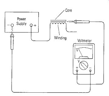
Figure 4-11. Using a Voltage to Test an Inductor for Breakdown Between Winding
and Core
• Turns Ratio
The turns ratio of a transformer can be measured using the circuit of Figure 4-10.
Apply a small ac voltage to the primary (Ve in Figure 4-10). A good source for this is a doorbell transformer. It supplies from 12 to 18 volts ac. Measure Ve with an ac voltmeter as shown in Figure 4-10. Now measure the secondary voltage V, with the same voltmeter. The turns ratio, is equal to N, Ne Vs v,, the secondary voltage divided by the primary voltage.
• Step-Up Transformer
Example: If V,, applied is 12 volts and Vs is measured as 60 volts, then the turns ratio is: or Ns _ 5 N,, - I The turns ratio is 5: 1.
• Step-Down Transformer
If the transformer is a known step-down transformer and the primary voltage is known, then the 110 VAC line voltage can be applied to the primary and the stepped down voltage read with the voltmeter.
Example: If VP is 110 volts and Vs is 10 volts, then
Ns _ Vs_ 10 V or Np - VP - ll0V Ns _ 1 Np -TI
The turns ratio is 1: ll.
If the primary voltage is unknown, or whether it is a step-up or step-down transformer, it may be dangerous to place 110 volts across a winding because the secondary voltage could be quite high if it has a step-up turns ratio. Thus, applying a lower voltage for the turns ratio measurement is a much safer condition. In each case, the secondary is not loaded when measuring the voltage to determine the turns ratio.
MEASURING SEMICONDUCTOR DEVICES
The only definite test for a transistor is operating it in the circuit for which it was designed. However, there are several tests that can indicate the condition of its junctions. There are sophisticated tests that can be made with oscilloscopes, curve tracers, and switching characteristics checkers, but we want to show how it is possible to test a transistor or other semiconductor device fairly completely with only an ohmmeter.
Diodes
The diode is a two-terminal, non-linear device which presents a relatively low resistance to current in one direction and a relatively high resistance in the other.
A "perfect" diode would act like a switch-either ON (Conducting) or OFF (Not Conducting) depending on the voltage polarities applied to the terminals. The typical construction and circuit symbol of a diode are shown in Figure 4-12a and 4-12b. The cathode of a diode is usually identified by some means of marking. On small-signal glass or plastic diodes, a colored band or dot may be used (Figure 4-12c). For rectifiers, sometimes a + is used to indicate the cathode (Figure 4-12e), or metal can devices have a large flange on the cathode (Figure 4-12d). Figure 4-13 shows a diode being tested with an ohmmeter. The proper indication is a high resistance reading when the ohmmeter plus ( +) lead is on the cathode (N material) (Reverse Biased -Figure 4-13b ), and a low resistance reading when the plus (+)lead is on the anode (P material) (Forward Biased-Figure4-13a). A low resistance both directions indicates a shorted diode; a high resistance both directions indicates an open diode. A condition were, respectively, high current has destroyed internal connections, or high voltage has broken down the junctions.
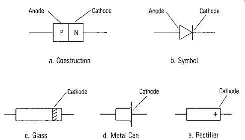
Figure 4-12. Diode Construction, Symbol, and Identification --- a. Construction
b. Symbol -- c. Glass d. Metal Can e. Rectifier
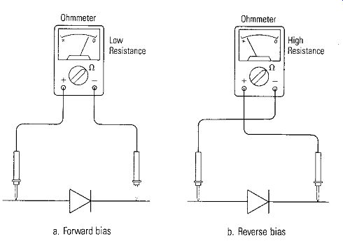
Figure 4-13. Using an Ohmmeter to Measure a Diode
a. Forward bias b. Reverse bias
Transistors
The transistor is a three-terminal device that has virtually replaced the vacuum tube.
There are two basic types of transistors: the bipolar and the field-effect transistor.
Bipolar Junction Transistors (BJT)
A transistor is a device made of two PN junctions as shown in Figure 4-14. The transistor is basically an OFF device and must be turned ON by applying forward bias to the base-emitter junction.
Transistors can be considered as two diodes connected back-to-back. Therefore, each junction, like a diode, should show low forward resistance and high reverse resistance. These resistances can be measured with an ohmmeter and the results should be as indicated in Figure 4-14. The polarities of the voltages applied are shown to indicate forward or reverse bias on the NPN and PNP transistors.
The same ohmmeter range should be used for each pair of measurements to each of the elements (base-to-collector, base-to-emitter, emitter-to-collector). For most transistors, any ohmmeter range is acceptable. However, in some meters, the R x 1 range may provide excessive current for a small transistor. Also, the highest resistance range may have excessive voltage at the terminals of some ohmmeters.
Either of these conditions may damage the transistor being tested. As a result it is best to start with the mid ranges for the resistance measurements.
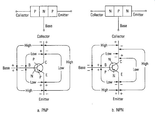
Figure 4-14. Resistance Readings Across Junctions of Transistors
• Defects
If the reverse resistance reading is low but not shorted, the transistor is leaky. If both forward and reverse readings are very high, the transistor is open. If the forward and reverse readings are the same or nearly equal, the transistor is defective. A typical resistance in the forward direction is 100 to 500 ohms. However, a low power transistor might show only a few ohms resistance in the forward direction, especially at the base-emitter junction. Reverse resistances are typically 20K to several hundred thousand ohms. Typically a transistor will show a ratio of at least 100 or so between the reverse resistance and forward resistance. Of course, the greater the ratio the better the device is for an application.
Operational Test of a BJT
The amplification action of a transistor may be checked with the circuit of Figure 4-15. It will give some indication if the transistor is operational. Normally, there will be little or no current between the emitter and collector (Iceo) until the base-emitter junction is forward-biased. Therefore, a basic operational test of a transistor can be made using an ohmmeter. The R x 1 range should be used. Closing S, will allow a small base bias current to be applied from the ohmmeter internal battery through R1.
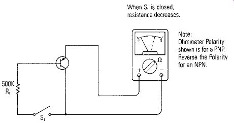
Figure 4-15. Operational Test of Transistor with Ohmmeter
When S, is closed, resistance decreases.
Note Ohmmeter Polarity shown is for a PNP. Reverse the Polarity for an NPN.
If the transistor is operational, the base current will cause collector current to flow, thus reducing the collector to emitter resistance. The ohmmeter shows a decreased resistance (an increased emitter-collector current) when S, is closed to indicate that the transistor is operational and amplifier action is taking place.
Field-Effect Transistors
A field-effect transistor (FET) is a voltage operated device that requires virtually no input current. This gives them an extremely high input resistance. There are two major categories of field-effect transistors: junction FETs and insulated gate FETs, more commonly known as MOS (metal-oxide-semiconductor) field-effect transistors.
Like the bipolar junction transistor, the FET is available in two polarities: P-channel and N-channel.
The schematic symbols for field-effect transistors are given in Figure 4-16.
Notice the terminals are identical for N-channel and P-channel but the arrow on the gate terminal is reversed. This also indicates that the current direction from source to-drain depends on the polarity type of the FET. Since there is no set designation for the source and drain terminals of the FET, the reference manual or the equipment schematic should be consulted to identify the terminals on the FET being tested.
Testing FETs is somewhat more complicated than a bipolar junction transistor.
First, determine from all markings if the device is a JFET or an MOS type.
Otherwise, the terminal measurements will have to indicate the type. Do not attempt to remove it from the circuit or handle a FET unless certain that it is a JFET or a MOSFET with protected inputs. If one touches the leads of these devices, static electricity can damage an unprotected device very quickly. Make certain all static electricity is grounded out before handling FETs.
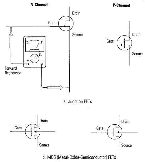
Figure 4-16. Field-Effect Transistors N-Channel -- a. Junction FET --- b.
MOS [Metal-Oxide-Semiconductor) FET
J-FET Measurements
To test the forward resistance of the JFET gate to source junction, use a low voltage ohmmeter on the R x 100 scale (or nearest to it). For an N-channel JFET, connect the positive lead to the gate (see Figure 4-16a) and the negative lead to either the source or drain. Reverse the leads for a P-channel. The resistance should be less than 1K ohms.
To test the reverse resistance of the N-channel JFET junction, reverse the ohmmeter leads and connect the negative lead of the ohmmeter to the gate and the positive lead to the source or drain. The device should show almost infinite resistance. Lower readings indicate either leakage or a short. Reverse the leads for a P-channel JFET.
Operational Test of a JFET
The following simple out-of-circuit test will demonstrate if a junction FET is operational but will not indicate if the device is marginal. Operational means it is not shorted or open, which is by far the most common occurrence when a FET becomes defective. After the JFET has been removed from the circuit, connect the ohmmeter between the drain and source terminals. Touch the gate lead with a finger and observe the ohmmeter polarity connections to the source and drain terminals and the channel type (P or N). Reverse the leads of the ohmmeter to the terminals and again touch the gate terminal. The ohmmeter should indicate a small change in the resistance opposite to that previously observed if the FET is operational. The change in resistance will be very slight and some operational (good) FETs will not appear to change.
MOS Measurements
To test a MOSFET, the device must be handled with caution and the hands and instruments must be discharged to ground before measurements are made. If a MOSFET is to be checked for gate leakage or breakdown, a low voltage ohmmeter on its highest resistance scale should be used. The MOSFET has an extremely high input resistance and should measure "infinity" from the gate to any other terminal.
Lower readings indicate a breakdown in the gate insulation. The measurements from source to drain should indicate some finite resistance. This is the distinguishing characteristic of a MOSFET; it has no forward and reverse junction resistance because the metal gate is insulated from the source and drain by silicon oxide. It should be a very high resistance with both polarities of voltage applied.
SCR Testing
An SCR is a gated diode that is used for the control of ac power. If a positive voltage is applied to the anode relative to the cathode, the diode will not conduct in the forward direction until triggered by current in the gate. Once triggered on, the diode is turned off by the voltage between anode and cathode going to zero. Testing with an ohmmeter is not recommended for high current SCRs and should only be used as a relative indication in low current SCRs. The current supplied by the ohmmeter may not be enough to "fire" or "hold" the SCR and therefore may not always indicate the true junction condition of the device.
However, a simple test of low power SCRs may provide an approximate evaluation of their gate-firing capabilities by connecting an ohmmeter as shown in Figure 4-17. The negative lead is connected to the cathode and the positive lead to the anode. Use the R x 1 scale on the ohmmeter. Short the gate to the anode with S,. This should Turn the SCR "ON" and a reading of 10-50 ohms is normal. When S, is opened and the gate-to-anode short is removed, the low resistance reading should remain until the ohmmeter lead is removed from the anode or the cathode. Now, reconnecting the ohmmeter leads to the anode and cathode should show a high resistance until S, is closed again to short the gate to the anode.
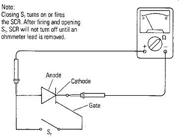
Figure 4-17. SCR Testing with Ohmmeter Note: Closing S, turns on or fires
the SCA. After firing and opening S,, SCA will not turn off until an ohmmeter
lead is removed.
TESTING A BATTERY
A battery is a single cell or group of cells that generate electricity from an internal chemical reaction. Its purpose is to provide a source of steady DC voltage of fixed polarity. The battery, like every source, has an internal resistance that affects its output voltage. For a good cell, the internal resistance is very low with typical values less than an ohm. As the cell deteriorates, its internal resistance increases preventing the cell from producing its normal terminal voltage when there is load current. A dry cell loses its ability to produce an output voltage even when it is out of use and stored on a shelf. There are several reasons for this, but mainly it is because of self-discharge within the cell and loss of moisture in the electrolyte. Therefore, batteries should be used as soon after manufactured as possible. The shelf life is shorter for smaller cells and for used cells.
Testing Under Load
A very "weak" (high internal resistance) battery can have almost normal terminal voltage with an open circuit or no load current. Thus, a battery should be checked under its normal load condition; i.e., in the equipment that it powers with the power switch on. Out of the equipment, the only meaningful test is with a load resistor across the battery as in Figure 4-18. The value of the load resistor depends on the battery being tested. For a standard "D" cell, RL = 10 ohms; a "C" cell, RL = 20 ohms; an "AA" cell, RL = 100 ohms; and a 9-volt battery, R1. = 330 ohms.
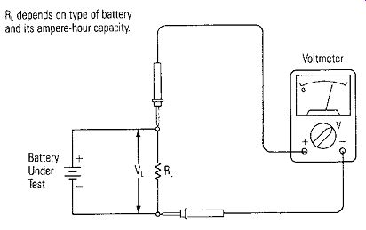
Figure 4-18. Testing a Battery Under Load RL depends on type of battery
and its ampere-hour capacity.
The terminal voltage should not drop to less than 80% of its rated value under load. The internal resistance may be calculated by the equation R1 = VNL - VL IL where VNL VL IL VL RL
the terminal voltage, unloaded
the terminal voltage with a load resistor
the load current which is equal to:
Measure V NL first without a load, then measure V L with a load, and calculate the internal resistance.
• Current Drain
The current drain of a battery should be measured in its actual operating condition; that is, with its normal load. It can be measured by connecting the current meter in series between the battery and the equipment it is powering. The battery clip may be disconnected from the battery on one side and the current meter connected to complete the circuit. The correct polarity must be observed. Start on a high current range in case of an excessively high current due to a malfunction.
Now that we have found out how to make measurements on individual components, let's look at how to measure components in circuits. That is the subject of the next section.