AMAZON multi-meters discounts AMAZON oscilloscope discounts
The most popular and versatile instrument on any electronics technician's workbench or in his toolbox is the multitester or multimeter. Understanding how to use multitesters to measure individual components is important, but understanding how to use them in making measurements in a circuit, the subject of this section, enhances their value many times over.
ABOUT IN-CIRCUIT COMPONENT TESTS
General Considerations
In-circuit measurements with a multitester usually occur with power applied to the circuit. These measurements usually are made because something has happened to cause a circuit, or a device, or a piece of equipment to operate improperly.
Measurements are being made to locate the problem. This is called troubleshooting the circuit. Because power is applied special safety precautions should be observed.
Make certain that measurement terminals are not shorted together or to ground by the test leads. This is especially so when 110 VAC line voltage is being measured.
Severe shock or extensive damage can result if caution is not exercised.
Meter Safety
The multitester will remain a valuable servant if reasonable care is taken while operating it. Specification limits should not be exceeded. Start out with high ranges when the value of the measurement is unknown, then move to lower ranges to bring the meter deflection upscale.
CHECKING A DC POWER SUPPLY
Each electronic system has a power supply, even if it is simply a battery. Let's look at a typical simple DC power supply, and how its voltage can be measured.
Basic Circuit Understanding
Typically, electronic power supplies consist of rectifiers, diodes, transformers, a filter made of capacitors and inductors or resistors, and a bleeder resistor, which can be used also as a voltage divider. Figure 5-1 shows a popular power supply circuit.
This circuit uses a full-wave, center-taped rectifier circuit to convert the ac voltage delivered by the transformer to DC. The pulsating current from the rectifier is smoothed by the filter. The bleeder resistors serve at least two purposes here. They provide multiple outputs, including one negative voltage with respect to ground.
They also provide a constant minimum load for the power supply to draw a minimum current and stabilize the output voltage.
Normal Operation Reference Values
Normal values of DC voltage, ac voltage, and resistances to ground expected in the circuit are very valuable reference values to a technician troubleshooting a power supply. Table 5-1 shows some typical values for the circuit of Figure 5-1 that should prove very useful.
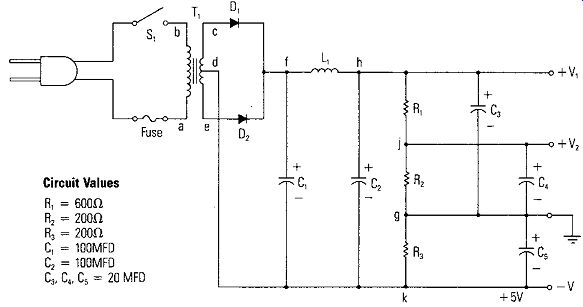
Figure 5-1. A Popular Power Supply Circuit
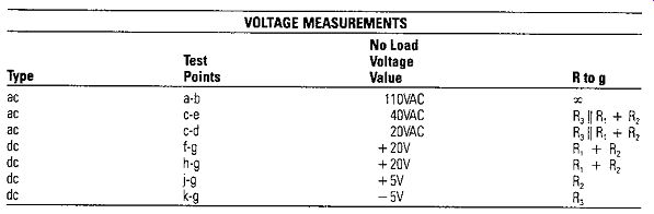
Table 5-1. Normal Voltage and Resistance Measurements
Locating Defective Components
Suppose in the circuit of Figure 5-1, that there is no voltage between point hand ground. In order to isolate the problem, a measurement is made to determine if input ac voltage is present. This ac voltage is measured between points c and e. If there is no voltage across c and e, it would indicate trouble due to defects in any of the following:
a. open line cord or defective line outlet plug.
b. open fuse.
c. open switch.
d. open transformer.
Voltage, continuity and resistance measurements are used to find and correct the problem.
If the above is not the problem and voltage is present at points c and e, then it is likely that the defect would be:
a. the load.
b. the rectifiers.
c. the filter inductor.
d. an open in the wiring between points c-e and h.
Disconnect the load from points V,, V,, and V,. If the voltage at h returns, then the problem is in the load. If not, check b, c or d. Voltage and resistance measurements to ground with Table 5-1 as a reference should isolate the problem.
Resistance Measurements
NOTE: Before measuring resistance, Turn power OFF and discharge all capacitors, especially if they are electrolytic. Specific circuit test points are selected so that resistance measurements can be made from the test points to ground to determine if there are circuit shorts or circuit opens. For example, if one of the filter capacitors is shorted (say C,), the resistance from point h to ground will be zero. When the trouble is found and the faulty component located and replaced, perform an operational check on the supply to make sure it is completely repaired.
TROUBLESHOOTING A SIMPLE AC CIRCUIT
A Doorbell Circuit - How It Works
Figure 5-2 shows a typical doorbell circuit. This circuit has the doorbell and switch in series with the transformer secondary winding. The doorbell operates at 10 VAC. This low voltage is not dangerous, and as long as the measurements are made on the secondary side of the transformer, it is not necessary to Turn off the circuit breaker to check out the circuit. The voltage measurements for a normally working doorbell circuit of Figure 5-2 are shown when the button is not pushed and when the button is pushed. M., M, and M, are different meter readings. If any of the voltages are not correct, the listed readings should help to determine the power supply problem. If not, then resistance measurements will have to be made. [NOTE: Turn the circuit breaker off ( or remove fuse) before making resistance measurements.] The resistances for a normally working doorbell circuit also are shown in Figure 5-2.

Figure 5-2. A Typical Doorbell Circuit ---- M,, M1 and M3 are different
measurements using the same meter.
When The Bell Doesn't Ring
Assume that the bell does not operate when the button switch is pushed. The two most common problems are a bad switch or a bad bell. To track down the trouble, measure the voltage across the push button switch. With the switch open, 10 volts should appear across the open switch. There is no current in the circuit and thus no voltage across the bell (M,). When the switch is closed, meter M, should read zero.
If a voltage appears across the switch even when it is closed, this indicates that the circuit is not operating properly. Check the contacts to see if they are corroded or broken. The switch can possibly be repaired by simply scraping and cleaning the contacts. However, it may have to be replaced. If 10 volts appears across the bell when the button is pushed and the bell does not ring, the bell is probably defective.
Disconnect it and check its resistance to see if it has an open coil.
Tracing a Short Circuit
Now let's assume that instead of an open we have a short in the circuit. We'll use voltage readings to find the short in the circuit. Assume that M, reads the normal zero volts when the switch button is pushed. However, M, reads an abnormal value of only 2-3 volts when the switch is open. It should read 10 volts. Now, measure the voltage across the transformer secondary (M,). It also is a low reading of 2-3 volts.
You note that the transformer is quite warm. You suspect a short so you disconnect one of the wires to the secondary, the M, voltage jumps to 10 volts. This indicates that there is a short circuit somewhere in the leads going to the doorbell. This short circuit drains so much current from the transformer secondary that it is overloaded and the output voltage is reduced to the low value of 2-3 volts.
To locate the trouble, examine the wires for frayed or worn insulation and possible points where they may touch. Sometimes a nail is driven through the wires scoring the insulation and causing the wires to short out with age. When you find the short, clear it and check for normal voltages as indicated above.
TROUBLESHOOTING YOUR TELEPHONE INSTALLATION
The fact that we can pick up our telephone and talk to almost anyone in the world is surely a modern miracle. Its dependability is amazing; however, there can be problems. Though you are not allowed to do repair work on the equipment owned by the local telephone company, you can make simple tests on the line and your own telephone instruments.
Testing the Telephone Line
A good way to determine if the trouble is on the telephone line or in one of the instruments is by substitution. If you plug a telephone that is known to be good into the line and it does not work, then you have verified that the line has the problem. If everything works, you know that the first instrument is the problem. If the trouble is on the line from the telephone company's central office to where it enters the house, the telephone company repairman will have to do the repairs. However, if the trouble is in your house, you can repair it yourself.
On Hook and Off Hook
The most common place for a telephone line to connect initially as it comes in from the outside is a 42A terminal block. Figure 5-3a shows a 42A terminal block and Figure 5-3b shows how four phone jacks are wired from the block. The incoming line and the branch lines can be tested with a VOM or a DVM. The DC voltage between the red and green wires should be about 48 volts with all of the telephones either "on hook" (hung up) or unplugged from their jacks. The minus (~)lead of the meter is connected to the red (ring) terminal and the plus ( +) meter lead is connected to the green (tip) terminal. An open or a short on the line can result in a zero voltage reading at a jack.
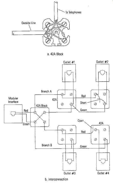
Figure 5-3. Initial Connection of Incoming Telephone Line --- a. 42A Block
--- b. Interconnection.
The voltage that will be measured across the line in the "off hook" condition (hand piece lifted and ready for use) will depend on several things; mainly the distance from the central office and the wire size used for the phone line. Typically the voltage will be from 5 to 10 volts dc.
Testing Branch Circuits
Let us now consider how to find a short or open at some point on one of the lines shown in Figure 5-3b. First, we will determine that the trouble is in the home and not on the phone line from the central office. At the 42A terminal block where the outside line enters the house, remove all the branch lines and measure the voltage. There should be about 48 volts DC with the red lead negative ( - ) and the green lead positive ( + ). Let us assume this is as it should be. A telephone set can be connected here and the line further confirmed to be good.
There are two branches from the 42A block: Branch A with two outlets, # 1, and #2; and Branch B with two outlets; #3, and #4. None of the outlets will work with a telephone set.
When Branch A is reconnected to the 42A, the 48 volts goes to zero. This means a short somewhere on Branch A. Going to outlet #1 and visually inspecting the connections indicates no short. If the wires that feed outlet #2 are removed at outlet #1 (even just one of them), the voltage at outlet #1 now measures 48 volts. A telephone instrument may be plugged in and it will work fine. Reconnecting the feed line to outlet #2 again kills outlet #1. Examination of the wiring at outlet #2 shows that the two wires are shorted together. After the short is cleared, outlets #1 and #2 work fine.
Branch B is now reconnected and outlet #3 checks okay but #4 does not. It has no voltage. Examination of the wiring of outlet #4 turns up a broken red wire, and therefore, an open circuit. Reconnecting the red wire to the outlet terminal screw restores voltage and operation to outlets #3, and #4. Plugging in a good telephone in all outlets shows that the system is operating properly.
Testing the Telephone Set
If it was determined that a telephone set is not operating properly, three problems are very common. A switch contact is bad, the talk and listen circuits are faulty, or the ringing circuit does not operate. Three quick tests can be made to isolate these problems.
• Measuring Resistance
In order to determine if the switch-hook contacts are operating properly, the resistance of the telephone set can be checked with an ohmmeter. Measure between the red and green wires leading to the telephone set with the set disconnected from its outlets or from the 42A block. This measurement is shown in Figure 5-4. With the handset on hook, the resistance should be infinity; with the handset off hook, the resistance should be 2000 to 10,000 ohms. Any reading below 1000 ohms indicates some problem with the telephone set. Further detailed troubleshooting would be necessary to locate the problem.
By measuring with an ohmmeter as shown in Figure 5-4, a clicking will be heard from the receiver of the handset to indicate that the talk and listen circuits are working properly. If the transmitter is an electrodynamic microphone, the clicks also will be heard from the mouthpiece.
Figure 5-4. Measuring the Handset with an Ohmmeter --- *Touch momentarily
to check talk and listen circuit
• Test of the Ringer Circuit
The easiest way to test the telephone set for ringer problems is to measure if ringing voltage is available. With the telephone set connected to the line, the handset on hook, and a voltmeter connected across the line as shown in Figure 5-5 at the 42A block (or the initial entry point into the house or apartment), have a friend or relative call your number. Ninety (90) volts ac voltage is applied at the central office across the line when the telephone is to ring. The amount of voltage at the telephone set depends on the distance from the central office. If the voltage appears but the telephone does not ring, more detailed troubleshooting would have to be done to locate the specific problem with the ringer. Be careful not to touch the wires with your hands or fingers. The ac ringing voltage can shock you.
OPERATION OF A BJT CIRCUIT
Normal Operation
Figure 5-6 is a typical kind of circuit that uses a BJT (bipolar junction transistor), in this case an NPN transistor, to be the active device in an amplifier circuit. Certain conditions must be met to make the transistor circuit operate properly. The base and emitter junction must be forward biased in order for the transistor to be turned on and conduct current. If the base and emitter junction is reverse biased (lack of forward bias) the transistor will be turned off and will not conduct current.
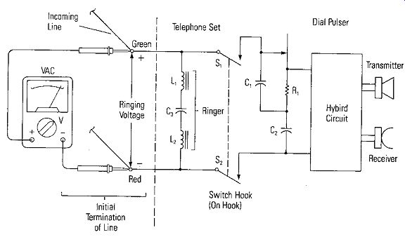
Figure 5-5. Measuring Ringing Voltage
The letters NPN or PNP tell us much of what we need to know about the voltages in the circuit for normal operation. For example, the center letter (Pin NPN) means the base must be positive with respect to the emit1 or to forward-bias it.
P must be positive and N negative to forward bias a PN junction. This letter also tells the polarity of the power supply applied to the collector in a BJT amplifier circuit, since the collector-to-base junction must be reverse biased. If the transistor is an NPN, a positive voltage is applied to the collector compared to the base and vice versa for a PNP. As the base voltage of an NPN transistor is increased with respect to the emitter, the base current increases, which increases the collector current. As the base-to-emitter voltage is decreased, the less the transistor conducts, until it stops completely. A conducting transistor normally has a high resistance between collector and emitter until it is driven into the saturation region (the region where the collector is only a few tenths of a volt away from the base). In a saturated transistor the resistance is low, and an increase in base bias (forward) results in no further increase in collector current. A saturated transistor may be considered near a dead short. Conversely, a cutoff transistor (one that has no collector current except leakage current) is a very high resistance, near an open circuit.
Measuring Voltages
An easy way to evaluate whether a transistor is operating properly in a circuit such as Figure 5-6 is to measure the voltages at the collector, base and emitter while the transistor is in the circuit. Figure 5-6 gives typical voltage values when measuring the voltage from ground to the respective transistor element of an NPN BJT.
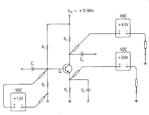
Figure 5-6. Transistor Amplifier for Normal Operation
The voltages could have been measured between the transistor electrodes, that is, from element to element, but the most common way, and the way most voltage values are given in service manuals and on schematics, is to have ground as a common reference as shown in Figure 5-6. Ground is usually the chassis into which the circuit is mounted, and very normally one terminal of the power supply.
• Junction Voltages
Silicon transistors normally have a difference of 0.6 to 0.8 volts between the emitter and base with the polarities depending on the type of transistor (NPN or PNP). As mentioned previously, the voltage between emitter and base will be in the direction to forward bias the junction; that is, positive on P material and negative on N material.
The collector-base junction is reverse biased, positive on the N and negative on the P. If the transistor amplifier happened to be made with a germanium transistor, the emitter-to-base voltage would be 0.2 to 0.3 volts. The types and polarities are the same as silicon.
• Steady-State No Signal Voltages
Voltages given in Figure 5-6 are the steady-state no-signal bias voltages. The transistor amplifier will usually be operated Class A. which means that the signal will increase or decrease the current in the transistor from that due to the no-signal bias voltages. Little change will occur in the emitter-to-base voltages, but large changes can occur in the collector-to-base (or collector-to-ground) voltage due to the voltage drop in the load resistor, R,, caused by the signal current change. The amount of shift is an indication of the amplifier’s gain.
Parallel Resistance Check
One of the simplest test to determine that the transistor is operating properly in the circuit is to place a resistor Rx equal in value to R, across R, (in parallel) in the circuit.
As shown in Figure 5-7, if the voltages are measured at the base, emitter and collector with respect to ground, we see that the voltages at the base and emitter are increased over what they were in Figure 5-6, indicating an increased base current.
The collector voltage is decreased due to the increased voltage drop across R, due to the increased collector current resulting from the increased base current. The emitter current and voltage has increased due to the increased base current and increased collector current.
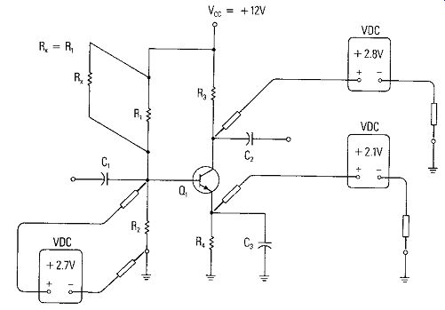
Figure 5-7. Increasing Transistor Current by Paralleling R,
Measuring Current Gain
Transistors basically are current amplifying devices. The small-signal current gain is the gain that is active in producing the amplification in Class A small-signal amplifiers like that shown in Figure 5-6. Even though the small-signal current gain and the DC current gain are not directly correlated, the DC current gain can be used as an indicator of the relative small-signal current gain available from a transistor.
To measure the DC current gain, the base current and collector current can be measured as shown in Figure 5-8, and the DC current gain, hFE, commonly called "Beta," can be calculated.
The common problem with Figure 5-8 is that circuit leads must be broken to insert the current meters. To avoid breaking the circuit, voltage measurements can be made across resistors as shown in Figure 5-9, and by using Ohm's law, the current through the resistors can be calculated. For example,
I ~ V,
' R, I - V, 2 - R~ I ~ V3 3 R3 I - V, 4
- R4
The collector current is 1 3 , the emitter current is I,, and the base current, Is, is Is ~ I, - I,
Therefore, hFE or Beta can be calculated using:
h _1; __ 1_3_ FE - IH - 11 - t
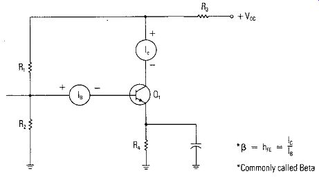
Figure 5-8. Measuring Collector Current and Base Current to Calculate Current
Gain
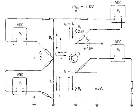
Figure 5-9. Using Voltage Measurements to Calculate Currents
DEFECTIVE TRANSISTORS
Open Junctions
If the transistor becomes defective, the most common faults are for a transistor junction to either breakdown because of overvoltage and short out, or to burn out because of excessive current and open. If a junction opens, the transistor will no longer draw current. The most obvious measurement to detect this condition is a measurement of the collector voltage. If the collector does not draw current, the collector voltage will be very near to the supply voltage. This voltage will be considerably higher than the voltage shown in Figure 5-6 as the normal no-signal steady-state operating voltage. There may not be a great deal of difference in the base voltage if the base-emitter junction opens because its voltage is commonly set by the bias resistor network of R, and R,, and not changed much if the small current into the base is stopped.
Shorted Junctions
If a junction is shorted, more than normal current is likely to flow and operating voltages will be affected accordingly. Suppose the collector-to-base junction is shorted. Now the collector voltage is likely to be much lower than normal because the current is controlled by the short circuit and not by the transistor. In addition, the base voltage is likely to be much different because of the loss of isolation of the collector junction.
If the emitter-to-base junction is shorted, the transistor action will stop. As a result, the collector voltage should be very close to supply voltage, emitter voltage will be the same as base voltage and the transistor is disabled. This case is shown in Figure 5-10, where a physical short has been placed across base and emitter with a clip lead. The voltage measurements are shown.
DEFECTIVE RESISTORS
Open R, Even though it is quite rare, let's demonstrate how BJT circuits can be analyzed considering the effect of certain resistor failures; that is, particular resistors opening or shorting. What would happen if R, of Figure 5-6 were to open? The voltage that result are shown in Figure 5-11. The no-signal steady-state condition of the transistor is not forward-biased and the collector is at the supply voltage. If a resistor doesn't have current through it, there will not be a voltage drop across it. The output signal, if any, would be grossly distorted. It would only be negatively going. Any negative going portion of the input signal would be clipped off because any signal present would be capacitively coupled to the base.
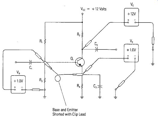
Figure 5-10. Shorting Base-to-Emitter to Turn the Transistor Off
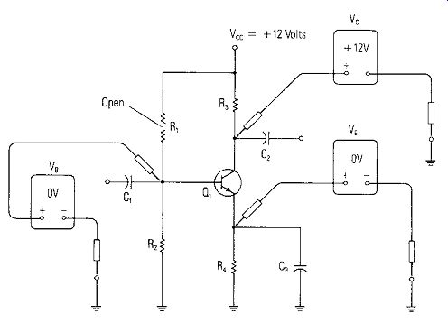
Figure 5-11. Voltages Resulting from an Open R,
Shorted R,
What would happen if R, were shorted? A short across R, puts a very high forward bias voltage on the base. The resistance of R, and R, in series is the only limit to collector current. The base-emitter current is limited only by R,. It is likely that the transistor will be destroyed. The initial voltages are shown in Figure 5-12. Note that the collector and emitter voltages are the same. The transistor is said to be in saturation.
Open and Shorted R2
An open R2 produces an increase in current similar to that discussed above for R1 shorted. Since the current through R, is now zero, there is less current through R,. The voltage drop across R2 is much less and the base voltage is much greater. The base current, in fact, rises to a value that completely turns on, or saturates, the transistor. Its collector voltage will be only about 0.1 volt above the emitter voltage and it cannot amplify signals. A short across R, is very similar to the condition shown in Figure 5-10 except the base and emitter voltages are zero.
Open R,
Now consider R,. If this load resistor is open as shown in Figure 5-13, the collector current is zero. Any emitter current must now be supplied by the base. The base emitter junction acts like a forward-biased diode which places R, in parallel with R2. Since R, is a small value of resistance, the emitter voltage falls to a very low value.
As can be expected, the base voltage will be its normal 0.6-0.7 volts above the emitter voltage.
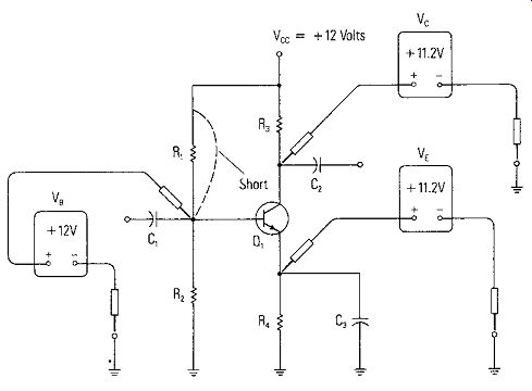
Figure 5-12. Voltages Resulting from a Short Across R,. 0, is in Saturation
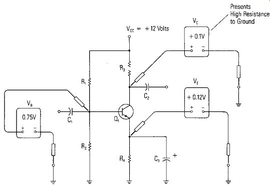
Figure 5-13. Voltage Resulting from Open Load Resistor R,
It might be assumed that the collector voltage would read zero since the load resistor is open. However, when a voltmeter is connected, it presents a high resistance path from the collector to ground. The collector-base junction acts like a forward-biased diode allowing a small current through the meter. Note the voltage from base-to-collector is 0. 75 - 0.1 = 0.65 volts in the forward-bias direction.
Open R4
Figure 5-14 shows the voltage values that result when R, opens. Since all transistor current is through the emitter lead, with an open circuit between the emitter and ground there is no current through the transistor. The collector voltage rises to Vee because of no voltage drop across R,. The voltage at the base is a result of the voltage divider R, and R,, and because the base current is relatively insignificant, it remains almost unchanged. The voltage at the emitter depends on the resistance of the voltmeter used to measure it. When it is connected, a small emitter current exists because the meter's resistance replaces R,. Therefore, the voltage at the emitter is slightly higher than normal. If the voltmeter measuring emitter voltage is left in place and the collector voltage measured, the collector voltage will be lower than + 12 volts because some small collector current will flow due to the completed emitter circuit.
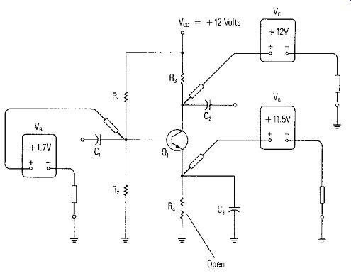
Figure 5-14. Voltages Resulting from an Open Emitter Resistor R4
Shorted R. A shorted R, is equivalent to a shorted C" since they are in parallel. Because capacitor shorts are common (resistor shorts are rare) this condition is more likely to occur than any we have discussed. The emitter voltage reads zero. The transistor, heavily forward-biased, saturates and passes a current limited by Vee- divided by R,. This normally prevents the transistor from being damaged. The base voltage will be clamped 0.7 volts above the emitter and the collector will measure 0.1 volts above the base. This is the approximate saturation voltage of a silicon transistor.
The function of C, is to provide an ac signal bypass across or around the bias stabilization resistor R,. If C, is open, an ac signal voltage will appear across R, introducing negative feedback into the amplifier circuit. The gain of the stage will be reduced by a value close to the ratio of R/R,. The DC voltages will remain unchanged.
A quick check is to shunt (parallel) the bypass capacitor C" with a known good capacitor of the same value. CAUTION: Shut off the power before connecting the shunt capacitor to prevent a large surge current from damaging Q,. Then reapply power.
A FIELD-EFFECT TRANSISTOR AMPLIFIER
An operating FET amplifier is shown in Figure 5-15. The normal operating no-signal steady-state voltages are shown. Although the functions of the capacitors in the FET amplifier circuit are similar to those in the BJT amplifier circuit, the results of failure are not necessarily the same. The values of capacitance are much smaller due to the higher impedances in the FET circuit. In the case where C, shorts in the FET circuit of Figure 5-15, the voltage from the preceding stage will be coupled to the gate and will increase the current through the FET. In some cases C, will only be leaky and not be shorted. Any voltmeter reading above zero at the gate indicates a leaky C,. With a leaky C., only a small portion of the voltage coupled from the previous stage will appear on the gate, but the effect is the same. A leaky C, reduces the reverse bias on the gate causing the drain current to increase, which will cause the drain voltage to be lower than the steady-state value and restrict the signal swing.
TYPICAL AMPLIFIER IN RADIO OR TV
Figure 5-16 shows a transistor amplifier circuit that might be designed into a television or radio receiver. Note that although the power supply voltages within the system are quite a bit higher than in the previous circuits, resistor divider circuits are used to step down the supply voltage for the circuit to the normal static voltages used in the previous circuits. R, may or may not be present.
GROUND REFERENCE AND CIRCUIT CONFIGURATION
Sometimes circuits are drawn or wired so that they look different from Figure 5-6. However, as far as the transistor is concerned, the operating conditions are the same.
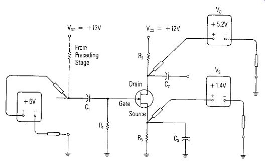
Figure 5-15. A Typical FET Amplifier Circuit.
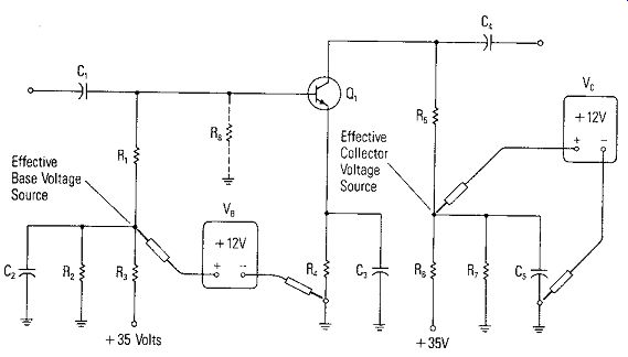
Figure 5-16. A Typical Amplifier in a TV or Radio Set.
Look at Figure 5-17 and compare it to Figure 5-6. Though the positive power supply terminal is at ground, the base bias network and collector load resistors are returned to ground also. The emitter resistor R, and the bottom base bias resistor R, are connected to the negative supply terminal. It is important to realize that the transistor bias voltages between its elements are identical in the two figures and that is what matters. If ground is used as a reference, the voltages will be negative. If the negative supply terminal is used as a reference, the voltages will be positive.
It is a matter of personal preference of some technicians to measure the voltage between elements of transistors directly. This is the fastest and least confusing method of establishing whether the bias on a transistor is correct. The method of specifying transistor voltages on schematics and in service manuals is from each element to a common or ground. The technician must then take the voltage measurement at each element to ground and subtract to find the bias voltage (difference in voltage between the elements). For example, the voltage on the base of the transistor in Figure 5-17 is - 8.0 volts from ground. The voltage on the emitter is - 8. 6 volts. The base-emitter voltage is + 0. 6 volts, the difference between - 8. 0 volts and - 8.6 volts. The base voltage is more positive than the emitter voltage.
With this section we have completed the individual component measurements and the measurement of components in circuits. In the next section we will look at common types of measurements that normally are made around the home.
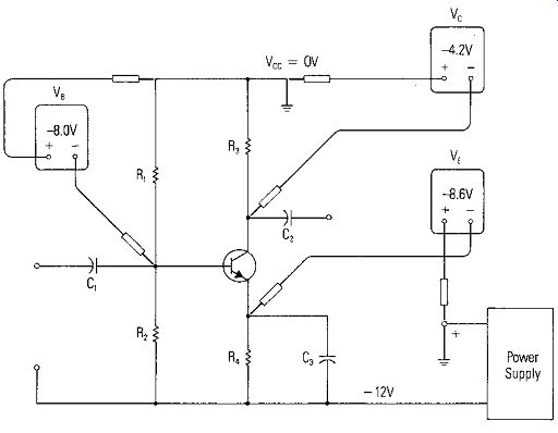
Figure 5-17. Transistor Amplifier Stage with Positive Ground Power Supply.