AMAZON multi-meters discounts AMAZON oscilloscope discounts
Having dealt with the measurement of components individually and in circuits, we now wish to summarize the various uses of a meter by discussing common measurements that one can make around the home to verify proper electrical circuit operation, identify a circuit problem if there is one, and correct or repair any improper operation. We will go through several applications in detail to indicate the procedure. Other applications will not include as much detail, but with schematics and our explanation of the circuit performance, the reader should be able to use similar procedures to check the circuit performance.
POWER DISTRIBUTION AND ELECTRIC LIGHTING
Even though Benjamin Franklin did his kite experiment with electricity in the 1700s and drew many important conclusions still practiced today, it wasn't until Thomas Edison invented the common light bulb (called an incandescent lamp) in 1879 that common use of electricity became widespread. Let's look at how electrical power is distributed.
Lighting Circuit
Figure 6-1 shows a common home power distribution panel. Three circuits are shown. A lighting circuit which has light bulbs wired across (in parallel) a 110-120VAC leg of the incoming power distribution. A 15 ampere circuit breaker is in series with one side of the line. The light bulb sockets are connected to the lighting circuit by quick connectors, called wire nuts, the plastic protectors that screw over wires twisted together. To measure the voltage at a light socket, an ac voltmeter on the 150V range or greater is used to measure the voltage at the twisted wire connections after the plastic wire nuts are removed. Or one lead of the voltmeter can be placed on the light switch terminal as shown. If the current is to be measured, and a clip-on ammeter is not available, the circuit can be broken at the circuit breaker and an ammeter inserted.
EXTREME CAUTION: Make sure the main power switch is turned off before making this connection. In fact, as shown in Figure 6-1, make sure there is no voltage at Point A before inserting an ammeter. With two 100W bulbs on the circuit, it would read approximately two amperes.
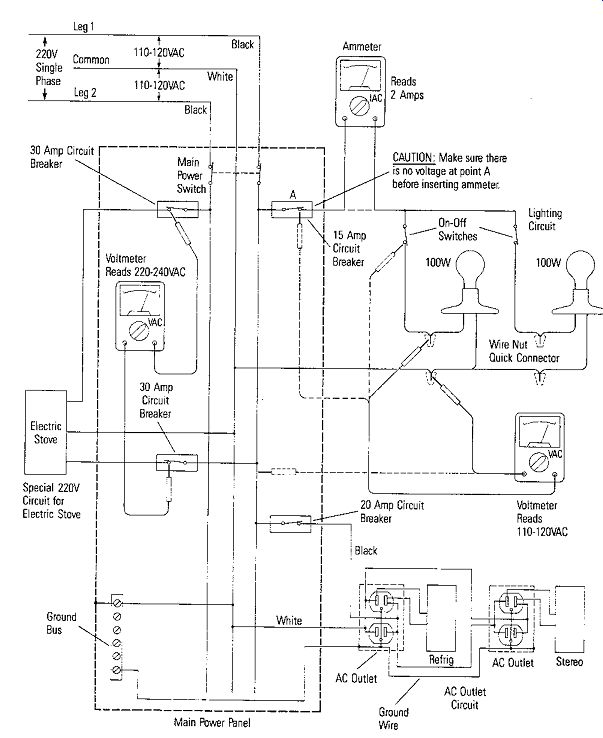
Figure 6-1. Home Power Distribution
Outlet Circuit
An ac outlet circuit is shown with a refrigerator and a stereo plugged into outlets.
If it is suspected that an ac outlet is not functioning properly, the ac voltage at the receptacle can be measured as shown in Figure 6-2 by following these steps:
1. Remove the suspected outlet receptacle face plate by removing the center screw.
2. Plug a lamp into a receptacle on the same circuit. Turn on the lamp.
3. At the power distribution panel, throw the circuit breaker OFF to Turn off the lamp.
This turns power off to the circuit feeding the receptacle; therefore, there is no danger of electrical shock as the receptacle is removed.
4. Remove the screws that hold the suspected outlet receptacle in the box.
5. Pull out the receptacle as shown in Figure 6-2.
6. Throw the circuit breaker ON back at the panel.
7. Measure the voltage at the receptacle as shown in Figure 6-2.
8. If there is no voltage look for broken wires, loose screws, or a damaged or cracked outlet.
9. Continue to isolate the problem by elimination working back to the power panel.
Some outlets receive their power by wires inserted into spring contacts at the receptacle. These spring contacts, in many cases, become defective and make poor contact. The connection is broken if the spring contacts do not make good connection.
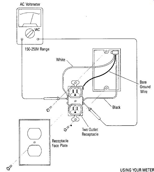
Figure 6-2. Measuring 110-120 VAC at Receptacle
• 220 VAC Circuit
In addition, a special 220 VAC circuit is shown for an electric stove. It is connected across both incoming power legs. As shown, the voltage can be measured easily by placing a meter across the two circuit breakers that are in separate voltage legs in the power panel. As a result, the 220V measurement is much safer because no wires or wire nuts need be removed to make the measurement.
Power Loss
Whenever current passes through a resistance, power is consumed in the form of heat. This power loss is often called FR loss and sometimes occurs at places such as poor wire connections, loose fuse connections, and rough or dirty contact surfaces on switches. If a poor connection is suspected in such places, an IR drop test can be made with a voltmeter. Touch the voltmeter probes on each side of the suspected connection while it is under load. If there is unwanted resistance, a voltage drop will be read on the voltmeter. Then, with the power off, the ohmmeter can be used to measure the resistance in ohms. Figure 6-3 illustrates this phenomenon and technique.
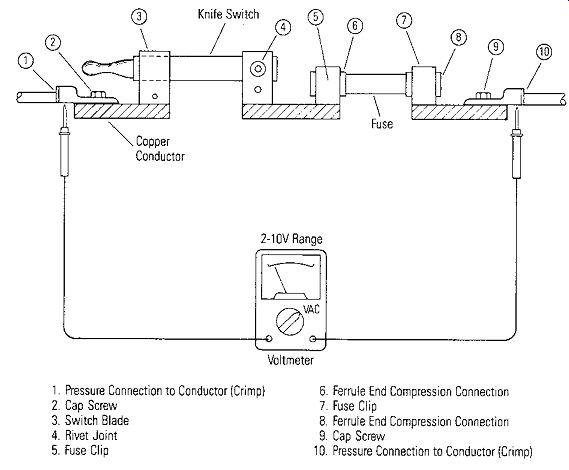
Figure 6-3. Possible High-Resistance Connections
1. Pressure Connection to Conductor (Crimp)
2. Cap Screw
3. Switch Blade
4. Rivet Joint
5. Fuse Clip
6. Ferrule End Compression Connection
7 Fuse Clip
8 Ferrule End Compression Connection
9 Cap Screw
10. Pressure Connection to Conductor (Crimp)
Shorts and Ground Faults
A short circuit occurs when current takes an accidental path short of its intended circuit. It is caused by the creation of a path of significantly lower resistance than that of the normal circuit. A short circuit can be damaging to an electrical system because of excessive currents that occur under a short circuit condition. Short circuits are usually caused by insulation between parts breaking down or wires shorting together because of vibration.
A ground fault is an accidental connection of a non-grounded conductor with the equipment frame or case. It is a form of a short circuit that results in current leaving the circuit conductors and going through a path of other conducting materials provided by the frame. It is usually a fault in insulation.
Both short circuits and ground faults can be located with an ohmmeter.
Check the circuit schematics of the equipment under test to determine the normal resistance in the circuit.
CAUTION: Be Sure That Power Is Off Before Measuring Ohms' Incandescent Lights
The incandescent lamp is basically a simple device whereby the electricity passing through the filament wire heats it so hot that it glows and gives off light. The amount of heat produced by the filament is determined by the wattage of the bulb. The wattage, in turn, is determined by the resistance and resultant current, according to Ohm's law, when a given voltage is applied. It is important to note that the resistance of the filament when it is cold is greater than it is when hot, so that a simple measurement with an ohmmeter will not be correct for finding the wattage of a lamp.
The "hot" resistance can be found by measuring the voltage and the current, then dividing the voltage by the current to obtain the resistance.
The incandescent lamp is very versatile and is found in many applications such as a small flashlight bulb, Christmas tree lights, all of the lights in an automobile, outdoor and street lights, and many other applications. Even though the incandescent lamp is most common, other types of lamps are often used for various purposes. The fluorescent lamp is one of these.
• Dual-Filament Bulbs
A popular incandescent table or floor lamp today is one that has a dual-filament (three-way) bulb which permits a single lamp to be turned to dim, medium, and bright settings by a special switch that connects the filaments singly or in parallel as shown in Figure 6-4. If a floor or table lamp is defective, the voltage from line to switch is measured with an ac voltmeter, as shown in Figure 6-4c, 6-4d, and 6-4e. If you want a quick check on a light bulb, the easiest measurement to make is a continuity measurement to make sure the filament(s) are not burned out. Figure 6-4a shows how to make a continuity check on the 3-way bulb using an ohmmeter. Continuity should be indicated, as shown in the schematic of Figure 6-4b, between the common outside base and the center contact A or the ring contact B. If the bulb where just a common single filament bulb, then there would only be a center contact A and the common base contact.
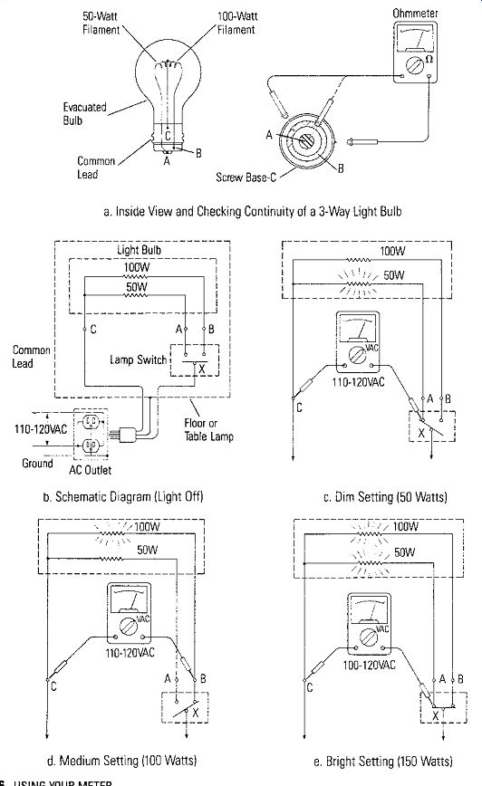
Figure 6-4. 3-Way Incandescent Lamp
a. Inside View and Checking Continuity of a 3-Way light Bulb
b. Schematic Diagram (Light Off)
c. Dim Setting (50 Watts)
d. Medium Setting (100 Watts)
e. Bright Setting (150 Watts)
Fluorescent Lights
The fluorescent lamp was introduced in 1939 and is much more efficient than the incandescent lamp. Fluorescent lamps require a starter circuit to heat filaments before sufficient electrons are emitted to ionize the mercury vapor gas inside the tube. After the gas is ionized, the resistance of the lamp drops so low that if it were connected directly to the power line, it would draw so much current that it would bum out very quickly. Because of this fact, a current limiting device (a ballast) must be connected between the lamp and the power source. The fluorescent lamp circuit is shown in Figure 6-5 with typical voltage measurements. If the starter never opens it would not allow the fluorescent bulb to light. The ballast and starter usually are contained within the fluorescent lamp's fixture. Some early fixtures had removable starters.
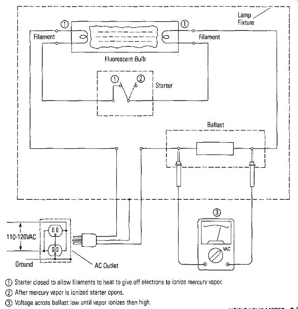
Figure 6-5. Fluorescent Lamp CD
-- Starter closed to allow filaments to heat to give off electrons to ionize mercury vapor.
-- After mercury vapor is ionized starter opens.
-- Voltage across ballast low until vapor ionizes then high
HEATING AND AIR CONDITIONING
One of the most common systems around the home is a heating and/or air conditioning system. In many homes, the furnace system to provide the heat is separate from a system to provide cooling. However, more and more homes are being built with a central system that contains both heating and air conditioning. We will use such a system as our example system. The heating system is a natural gas or electric hot-air distribution system and the air conditioning system is a freon system with compressor and condenser outside and the evaporator inside above the hot-air furnace. The furnace blower is used in both cases to distribute the hot or cold air throughout the house.
Electrical Circuit
Figure 6-6 shows a typical schematic wiring diagram for the example central heating and air conditioning system. The thermostat has two switches. One that controls the system function- HEAT, COOL or OFF, and one that controls the fan either to be on continuously or to come on automatically when the system cycles. When the system switch or the fan switch is in a set position, the contacts are shorted together as shown in Figure 6-6. FR is a relay that controls a two-speed fan motor through contacts FR, and FR,. CR is a control relay that controls the operation of the compressor through the dual-line contactors CR, and CR,. The power source for the fan relay and the compressor control relay is 24 volts stepped down through a transformer TR, from 110-120 VAC. The 24 volts is also the power source for the gas control valve which is turned on when heat is required. A gas pilot ignites the gas in the combustion chamber. In Figure 6-6, a heater relay also is shown for an electric heating system. The system would have either the gas control or the electric heaters. Once the fan relay is energized, the contacts FR, and FR, connect 110-120 VAC to run the motor. 220 V AC is the power source for the compressor and the electric heater, if there is one.
General Problems
Most of the problems with the heating or air conditioning system will be in the low voltage control circuits. Rarely do the relays go out, unless their contacts are burned due to a short in the motor, compressor or the heating element.
If the compressor doesn't run or the electric heating element doesn't heat, a simple continuity check will indicate if the compressor or heating element are burned out.
THROW ALL MAIN POWER SWITCHES TO OFF before making the check as shown in Figure 6-6.
EXTREME CAUTION SHOULD BE TAKEN BECAUSE 220 VAC IS THE POWER SOURCE. Check with a voltmeter to make sure no voltage is present across the contacts to be measured. No continuity indicates that the windings of the compressor or heating element are open. Find the CR or HR and make the measurement at the contacts as shown in Figure 6-6.
The best way to find a problem if the heater or air conditioner doesn't work is to isolate the system operation into the respective heating and air conditioning functions.

Figure 6-6. Typical Central Heating and Air Conditioning System
Heat Cycles
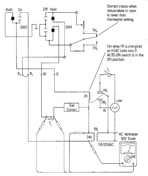
Figure 6-7. Heat Cycle ----- Contact closes when temperature in room is
lower than thermostat setting.
Fan relay FR is energized on HEAT cycle only if AUTO-ON switch is in the ON position
Figure 6-7 shows the schematic of Figure 6-6 when in the heating mode. Only the circuitry associated with the heating function is shown. The function switch is in the HEAT position and the fan switch is in the AUTO position. If the system is operating properly, the thermostat contacts TH8 would be closed because the thermostat was turned up to a temperature higher than the temperature of the space to be heated; thus, demanding heat. Closing TH8 energizes the gas control (or the heater relay) turning on the gas flow which burns and generates heat. As soon as the inside of the furnace heat exchanger reaches the T F temperature, the thermal switch T F closes and energizes the low speed of the fan motor through the closed contacts FR,. When the room temperature rises and causes TH" to open, the fan motor continues to run until the furnace plenum is cool enough to cause T F to open. If the AUTO-ON switch is placed in the ON position, FR is energized, the high speed of the fan motor is energized through contacts FR,, and the circuit through contacts FR, is opened.
Heated air is delivered to the space to be heated. If the temperature inside the furnace ever exceeded TL, the thermal switch TL would open and disconnect the power from the gas control to shut off the gas. Of course, for a gas furnace, the pilot light must be on before the gas control will work, so if the furnace is not heating the pilot may have gone out, or the pilot gas control thermocouple may be defective and must be replaced.
If the pilot is on and the furnace does not come on when the thermostat is turned up, follow these steps:
1. Remove the panel from the furnace and the cover from the thermostat.
2. Measure the voltage across the secondary of the 24V low voltage control transformer as shown in Figure 6-7.
If there is no voltage at the secondary, measure the 110-120 VAC at the primary. If there is no primary voltage, check the furnace circuit breaker at the power panel. If there is primary voltage and no secondary voltage, Turn off power and measure the continuity of the secondary to make sure it is not burned out.
3. If 24V is present, manually operate TH so that TH" closes and determine if gas flows and the furnace flame comes on. If gas does not come on, switch SW, from OFF to HEAT several times to determine if the switch contacts may be corroded and not completing the circuit correctly. Voltage measurements around the loop as shown in Figure 6-7 should isolate the problem.
4. The same procedure can be used to isolate a problem in the fan circuit. However, a first easy check of the fan circuit is to Turn the fan switch to ON, which will make the relay operate and the fan to run continuously. If this is not the case, operate the switch several times, maybe the contacts are corroded. A common problem is that the thermal switch, T F, has gone bad. Make voltage measurements around the circuit to isolate the problem. The 24 volts will be safe and will not shock you, but be very careful when making measurements in the 110VAC fan motor circuit.
Cool Cycles
Figure 6-8 is the schematic when the system switches are set to COOL and the fan switch is on automatic. The temperature in the space to be cooled is higher than the thermostat setting, thus THc is closed to demand cooling. When THc closes, it completes the circuit to supply 24 volts to CR the compressor control relay. The compressor runs and supplies coolant to the evaporator mounted in the air flow path in the furnace.
At the same time the THc completes the circuit for CR, it also completes the circuit to supply power to the fan relay FR through the fan switch in the AUTO position. This turns on the blower motor and the room air is driven over the evaporator to supply cool air to the space to be cooled.
Isolating a Problem
Obviously, if the air conditioning system is not cooling, many problems could be present besides the electrical circuit; therefore, a qualified air conditioning repair person must be called to isolate the problem. However, several simple checks will determine that the electrical circuit is operating properly.
• Fan Or Blower Motor Circuit
First of all, the fan circuit can be checked easily by placing the fan switch in the ON position. This should make the furnace blower run continuously. As shown in Figure 6-8, moving the fan switch to ON completes the circuit to supply 24 volts directly from the secondary of TR, to FR, the fan relay. If the fan does not come on, move the fan switch from AUTO to ON several times; the contacts may be corroded and the movement may burnish them to make contact.
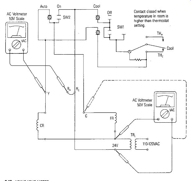
Figure 6-8. Cool Cycle
If the fan still does not come on, remove the furnace panel and isolate FR and TR,. First measure the secondary of TR, to assure that the transformer is operating properly and supplying 24 volts, second, measure voltages around the circuit as shown in Figure 6-8 to isolate the problem. The FR relay will make a noise when it operates. If it operates when the fan switch is turned to ON but the blower doesn't come on, then there may be problems with the contacts FR, of Figure 6-6 and Figure 6-7, or the blower motor maybe burned out.
WITH THE FURNACE AND AIR CONDITIONER CIRCUIT BREAKERS OFF AT THE POWER PANEL continuity checks can isolate the problem.
• Compressor Circuit
The compressor control relay CR receives its 24 volts supply through a circuit that is completed through the contacts of SW, when the switch is in the COOL position. CR will be located in the air conditioning condenser that is mounted outside the house or building to be cooled. The compressor controlled by CR is also located there. If the temperature in the room is higher than the thermostat setting, THc should be closed and CR should operate when SW, is placed in the COOL position. A person located near the condenser can hear CR operate when SW, is placed in the COOL position.
The compressor should turn on when CR operates. If CR is operating and the compressor turns on, and the blower motor turns on, but the unit still does not cool, an air conditioning specialist should be called.
If CR does not operate, then check to determine that TR, is supplying 24 volts properly. An easy check of this is to remove the thermostat cover and measure the voltage at Y and Re, RH of Figure 6-8. When THc is open (thermostat set higher than temperature in the room) then the voltage across Re, RH and Y should be 24 VAC. When THc is closed, the voltage should be zero volts. Just with these simple checks one can determine if the electrical circuits are operating properly.
If CR operates but the compressor does not come on, the contacts CR, and CR, may be bad or the compressor may be burned out. Call an air conditioning specialist if the problem is isolated to this point.
CAUTION: IF CR IS OPERATING PROPERLY AND THE COMPRESSOR COMES ON, DO NOT CYCLE THE COMPRESSOR FROM ON TO OFF RAPIDLY. IT MAY OVERHEAT THE COMPRESSOR AND CAUSE A THERMAL SWITCH INSIDE TO OPEN. WASHER AND DRYER CIRCUITS
We will not go into detail with respect to locating and isolating problems with the washer and dryer electrical circuits. We will just present the circuit and a short description of the circuit operation and expect that, after the above examples and the material in the preceding sections, the reader will be able to follow measurement procedures for continuity, voltage, current and resistance and isolate any problems.
To that end the following are some overall guidelines.
Troubleshooting an Electrical System
In almost all cases, troubleshooting the electrical section of a system is straight forward and usually simple. Always apply basic rules of electrical theory when testing any circuit. Remember, if theory and practice do not agree, it means either incorrect theory or incorrect practice! The first step in troubleshooting any circuit is to have a clear understanding of the circuit and its function before starting. If you do not understand how a circuit functions when there is no problem, it is almost impossible to troubleshoot the circuit because you may not know what you are looking for. This does not mean you must have a total understanding of the circuit, but it does mean that you must have a general overall knowledge of the circuit's function.
The next step is to eliminate the obvious, no matter how simple it may seem.
This includes first checking the fuses, circuit breakers, and overload resets. If careful observation does not yield recognition of an out-of-the-ordinary condition, then the problem must be isolated to the control circuit, power circuit, load, or incoming power. Each of these areas, although connected and related, can be isolated one from the other to make troubleshooting easier.
The following is a step-by-step procedure.
1. Eliminate the incoming power supply as the source of problems by measuring the 220 volts or 110 volts that are the main supply. One of the most common troubles found in all electrical circuits is a blown fuse or tripped circuit breaker.
2. Usually the control circuit of most systems is at a low voltage -- 24 volts is common. Isolate it and measure it and make sure it is operating properly. Usually the presence of the 24 volts can be used to indicate continuity through a particular branch of the control circuit.
3. Electric drive motors, fan motors, and heaters are common electrical loads.
Electric motors are essentially reliable machines and require little maintenance in comparison to the rest of the circuit. Check the voltage at the motor to see if it is the correct level, that is, if it matches the nameplate voltage within 10%. If the voltage is correct at the motor, but it does not run, there may be an internal thermal switch in the motor that has become defective or is open because the motor is hot.
The electrical loads are controlled through relay contactors that are controlled by the low voltage circuit. Even though low voltage is present and the relay is operating, it does not mean that the contacts themselves are not defective.
WASHING MACHINE ELECTRICAL SYSTEM
The Electrical Circuit
One of the biggest stumbling blocks encountered when servicing an appliance is the variety of wiring diagrams or worse yet, the lack of a diagram at all. Each manufacturer has his own idea of a wiring diagram. Once you have interpreted the schematic, wiring diagram, and/or the operation chart, the appliance will be much easier to troubleshoot. Figure 6-9 shows a typical wiring diagram as it would appear on the back of a washer. You will have to know what is suppose to happen and when it is suppose to happen before you can tell if there is anything wrong.
Timers
The timer in an appliance may be thought of as the "brain" of the machine, because it controls the sequence of operation. It generally consists of three basic components assembled into one unit:
1. The timer motor
2. The escapement
3. The cam switchbox.
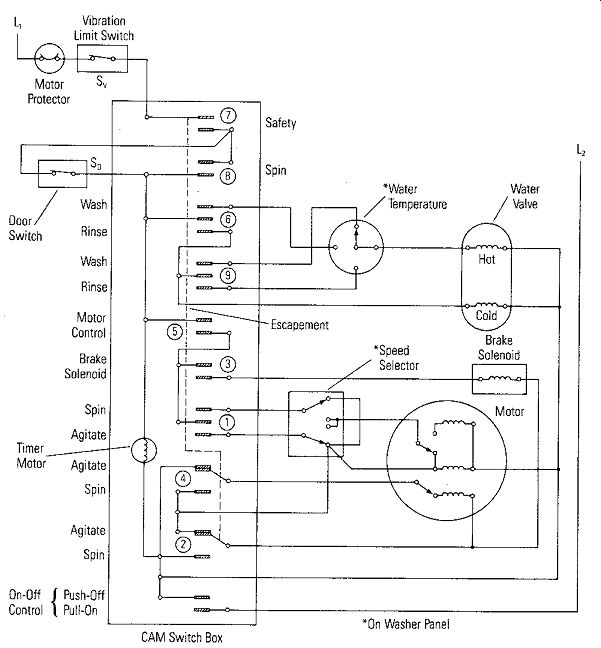
Figure 6-9. Wiring Diagram of Automatic Washer Showing Electrical Connections
from Timer to Other Electrical Parts
The motor is an electric-clock type geared down to a small pinion gear that drives the escapement, which drives cams in the earn switchbox to close switches 1 through 9 in a timed sequence. Obviously, if the timer motor is defective, only the motor should be replaced, not the entire timer. The purpose of the escapement is to rotate the earn shaft in a series of timed pulses. It is not generally serviceable and a problem here normally requires replacement of the total unit. The cams in a timer open and close the electrical switch contacts, thereby controlling the sequence of operations.
A cycle-sequence chart, shown in Figure 6-10 tells when a circuit is active, and also at what time in a cycle a particular function is in progress.
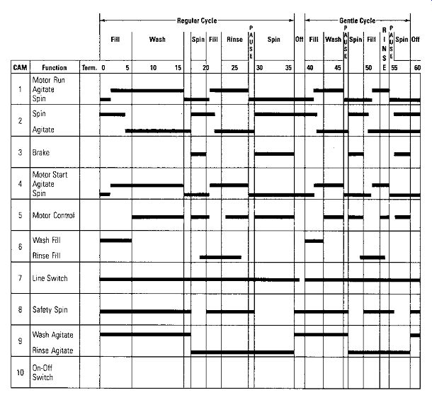
Figure 6-10. Washing Machine Timer Cycle-Sequence Chart
Safety Switches
There are switches that are designed to provide safer operation of the machine; For example, a switch to open and stop the spin action when the door is opened (S0 ), or another to detect an unbalanced load (Sv). These switches are common suspects for open circuits. The water temperature and speed switches are not as likely to become defective.
Troubleshooting
With the aid of Figure 6-9 and 6-10, one can tell if voltage is to be applied to the motor or the hot or cold water valves. With power off, trace the circuit, using an ohmmeter for continuity, to locate accessible terminals where voltages can be measured.
110 VAC can be measured to verify proper operation. No low voltage control voltage is available in this circuit. Be very careful not to short out the 110VAC. DRYERS The electrical circuit of dryers is very similar to washers in that it contains a timer motor, escapement and a cam switchbox. However, the circuit is much simpler because basically there is only one function being performed~ blowing hot air through the clothes for a given amount of time to dry them. The heating element is resistance wire which glows when a voltage is applied. The voltage is 220-240VAC. The drive motor to turn the tub that tumbles the clothes operates from 110-120 VAC. This motor also drives a blower that moves air through the dryer and vents it outside the dryer. The circuit diagram is shown in Figure 6-11. To understand the operation, let's look first at the safety switches.
Safety
Features If the drive motor is not turning the tub, there will be no power to the heating elements. The 220-240VAC circuit is held open by C,,, the centrifugal switch that is on the drum drive and blower motor. CF2, as well as C", closes when the motor is at the correct speed. C" disconnects the start winding of the motor after the motor is at the correct speed. It also closes the circuit to the buzzer and the cool-down thermostat.
The cool-down thermostat closes when the temperature inside the dryer rises to its operating temperature. It does not open again until the temperature cools below this temperature. An exhaust temperature thermostat is located in the exhaust port of the dryer. It is normally closed and will not open unless the exhaust temperature exceeds a given temperature set by the manufacturer of the thermostat. As a double precaution against the dryer rising above a maximum temperature, there is a second safety switch in the heating element power circuit. It is a high-temperature safety thermostat that opens the circuit if the temperature were to rise above a maximum set by the thermostat.
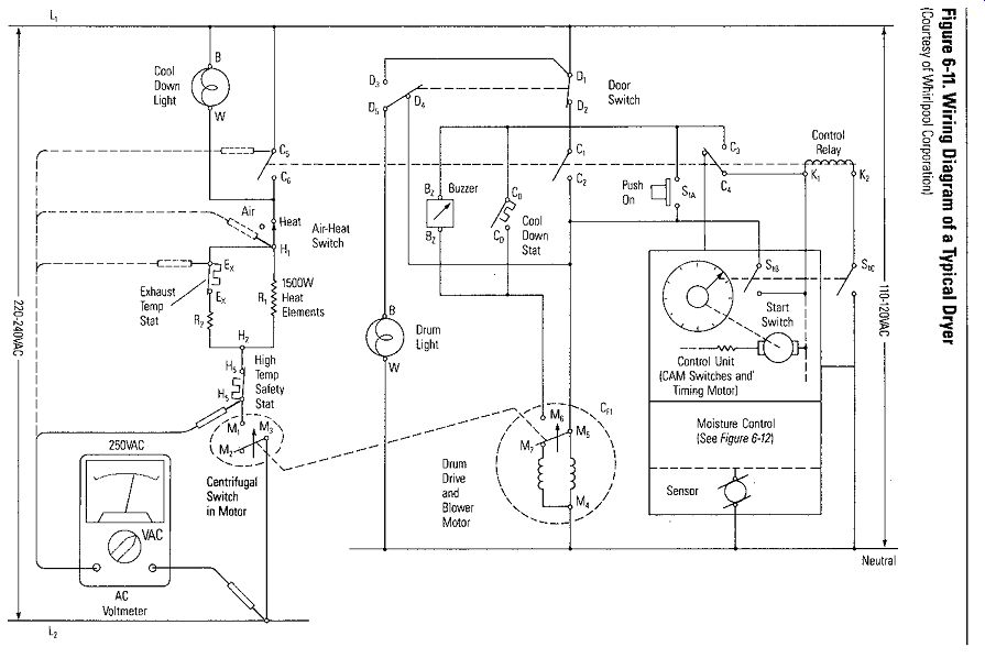
Figure 6-11.
No power will be applied to the drive motor or the control relay circuits unless the door of the dryer is closed. The door switch closes contacts D, and D, to complete the power circuits. No power could be applied to the heating elements because the control relay would have no power and contacts C, and C would be open.
Dryer Operation
The start switch, Sm and S,c are closed by setting the timing control on the control unit to the appropriate time or time cycle desired. The power circuit to the control relay is completed by pressing the momentary push button, SL,, which energizes the control relay and closes contacts C, and C,, C, and C,, and C, and C6
• C1 and C2 complete the power circuit to the drive motor for the drum and blower, and C, and C, complete a holding circuit for the control relay so it will remain energized after S" is released. C, and C6 complete the power circuit to the heating elements if the air-heat switch is in the HEAT position. No power would be applied to the heating elements if the air-heat switch is in the AIR position. Just room temperature would be circulated through the clothes when in the AIR position.
When the timer times out, Sm and S,c are opened and the control relay is deenergized opening contacts C, and C,, C, and C.,, and C, and C6 •
Even though contacts C, and C, are open, the drive motor doesn't stop. The cool-down thermostat continues to complete the circuit until the temperature cools below the limit. The power circuit in this case is through the cool-down thermostat contacts C0 and through the M6 and Ms contacts of the centrifugal switch in the motor.
Once the cool down thermostat opens power is disconnected from the motor.
However, until the motor slows down the M6 and M, contacts remain closed to supply power momentarily to the buzzer that signals that drying is complete. Cool down is indicated by a light bulb that receives its power when C, and C6 contacts of the control relay open. It remains on until the M1 and M, centrifugal switch contacts in the heating element circuit open when the drive motor stops.
The circuitry is straightforward with door safety switches, temperatures sensitive switches that turn off the heating element if the temperature of the air over the clothes is too hot, and a centrifugal switch in series with the heating element that keeps the power circuit to the heating element open if the motor is not turning the tub. In other words, the motor that tumbles the clothes must be running before power is applied to the heater.
Troubleshooting a Dryer
A common problem with dryers is that the heating element bums out. With power off (pull the plug from the receptacle in the wall), check the continuity of the heating element with an ohmmeter. This can be done easily by removing the back panel.
Check the schematic carefully to determine the proper interconnections.
If safety switches or thermostatic switches appear to be defective, voltage measurements should isolate any defective components. In Figure 6-11, an ac voltmeter on the 250VAC range is used to measure at various points in the heater element circuit. This is a 220VAC circuit so measurements must be made very carefully. Remember that the meter completes a circuit so that voltages will appear across open switch contacts if the rest of the circuit is complete. In many cases, if a switch is operating properly and the rest of the circuit is complete, 110VAC or 220VAC will appear across the contacts if the switch is open, and zero volts if the switch is closed.
Moisture Sensor Control
A different kind of control found on dryers is a moisture sensor to control the drying cycle. Figure 6-12 shows such a circuit. T" is the dryer timing motor that drives the cams and controls the switches in sequence. 110-120 VAC supplies power to the circuit through L, and neutral.
The circuit works as follows. When wet or damp clothes are in the dryer and it is set on the cycle controlled by the sensor, S0 , the moisture across S0 will make it a low resistance. On the negative alteration of the ac line voltage, the diode D, conducts and drains current through Re. R,, and R,. The voltage drop across R, (usually greater than 70 to 75 volts) causes the neon lamp N, to fire and draw current through R,, R, and the SCR (Silicon Controlled Rectifier). The level of current is high enough to trigger the SCR. The triggered SCR effectively shorts out the timing motor and the timing motor stops.
When the clothes dry to the point where the sensor is no longer a low resistance, the current through R, no longer maintains a voltage drop high enough to fire the neon bulb. As a result, the triggering current to the SCR stops, the SCR turns off, and the timing motor starts and completes the drying cycle.
Troubleshooting the Sensor Circuit
The four components most likely to become defective are the sensor, the diode, the neon bulb and the SCR. If the dryer cycle is quite short so that the clothes never dry, anyone of these components could be at fault. One easy check for the neon bulb is to see if it glows when damp clothes are in the dryer. If it does, it is likely that the sensor, diode and neon bulb are all ok. The SCR may be defective.
If the neon bulb is glowing and the timing motor is running, it is a pretty fair indication that the SCR is defective. Remove it from the circuit and using an ohmmeter test the semiconductor junctions as discussed in Section 4.
If the neon bulb does not glow and the timing motor is running, measure the voltages at point 1, 2, 3 and 4. The voltage drop across S0 , R,, D, and R, can be calculated as follows: Voltage Drop Across Voltage at Point 1 Point 2 - Point 1 Point 3 - Point 2 Point 4 - Point 3 If R, is a very small voltage, either the sensor S0 or the diode D, may be defective.
Remove them from the circuit and measure S0 and D, independently as discussed in Section 3.
If D, is suspected as being defective, its forward and reverse resistance can be measured with an ohmmeter as shown in Figure 6-12 if the power is removed from the dryer by removing the ac plug.
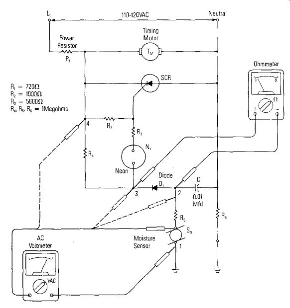
Figure 6-12. Electronic Dryness Control (Courtesy of Whirlpool Corporation)
A SMOKE ALARM
The Circuit
There are two common types of smoke alarms in use: the ionization-chamber type, which is comparatively new, but widely distributed; and the photocell type, which has been widely used in industrial security systems for many decades, but has just recently been adapted to home use.
Ionization Chamber Detectors
In this system a tiny amount of radioactive material is mounted in a sensing chamber; it ionizes the air present, making it conductive. A 9-volt battery causes a flow of electric charges across the air gap of the sensing chamber. If fire-caused ions in the form of gases or smoke enter this ion chamber they interfere with the movement of electric charges across the air gap, causing a change in current. This is sensed by the electronic circuitry, which turns on the alarm, basically, an audio oscillator.
Photoelectric Cell Detectors
Basically the same principle as an infrared LED light source directed in a narrow beam that strikes a photocell and sets up a current is used here. However, a small baffle in the path prevents light directly from the LED from reaching the photocell.
When smoke is present, it reflects a portion of light around the baffle to the photocell, which, in turn, triggers the alarm. On the outside, the two detectors look exactly alike.
Troubleshooting
The cost of most smoke alarms is so low that it is probably impractical to have them serviced. However, you can make some checks on it with your VOM. The system can be viewed as in Figure 6-13. Almost without exception, the detector, the battery, and the transducer are very similar in all smoke alarms. The two circuits on the PC board, however, will vary greatly. They may be contained in a single chip IC or be constructed of discrete components. If it is constructed with discrete resistors, capacitors, and transistors, trace the circuit using a VOM as an ohmmeter for a continuity tester. Then you can check the components in the circuit by the methods discussed in Section 2.
The most obvious problem is a drained battery. The battery voltage, usually 9 volts, can be checked at the point where the leads enter the PC board, or at the battery clip (Figure 6-13). The transducer is usually one of two types of a ceramic piezoelectric buzzer. Either it is one with a built in driver, or else it is one requiring an external driver. The resistance across the transducer leads is about 16 ohms. Most smoke alarms have a test button that bypasses the transducer with a short circuit and sounds the alarm. This becomes an easy check on the battery. If the alarm does not sound under this check, measure the battery voltage with your VOM as shown in Figure 6-13.
TAPE OR CASSETTE RECORDERS/PLAYERS
The first tape recorders made use of open-reels for holding the tape. These have been replaced almost totally by the smaller, easier to use cassette version.
Regardless of the type, a tape recorder/player also may have a built-in microphone, level meter, or a complete AM-FM radio.
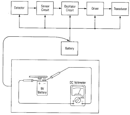
Figure 6-13. A Basic Block Diagram of a Typical Smoke Alarm
The Drive Motor
Drive systems, including the motor and the motor speed control, must produce steady and accurate drive power because the accurate reproduction of the recorded signal depends on a constant rate of tape motion across the head. Special control circuits such as PLL (phase locked loops) are used on the more expensive tape recorder systems to maintain constant speed. If it appears that the speed is varying, the voltage across the motor can be monitored with the DVM or VOM during the record/playback function to make sure there is no variation. If there is variation, check the transformer feeding the power supply or any capacitors in the power supply. If the drive is inoperative (the tape doesn't move) voltage measurements across the motor would be a first check. Absence of voltage would indicate trouble in the power supply; presence of proper voltage and no tape movement indicates a possible defective motor if one makes sure that the tape or any motor parts are not jammed. Turn off power and use an ohmmeter to check the motor's continuity and resistance.
Record/Playback Heads
Every tape system has at least one head and possibly two or three. Tape heads are basically electromagnets for converting audio amplifier signals into magnetic fields during recording, or for converting a magnetic field variation on the tape into an electric signal during playback. The magnetic tape moving across the heads acts as an abrasive that wears away the soft head metal. Head wear is the most common problem with tape heads but they can, because of the extremely small wire that is inside the head, open or short circuit. If there is no playback signal when in the PLAY mode, even from tapes that are known to have signals, a quick check should be made of the amplifier. The amplifier quick check can be made by plugging in a headphone and putting the recorder in the RECORD mode. Sounds picked up by the microphone should be heard in the headphone. If the amplifier is working properly, the trouble in a nonfunctioning recorder is in the head or the RECORD/PLAY switch.
To check the heads with an ohmmeter the connecting wires should be removed after carefully identifying them by making a brief sketch as shown in Figure 6-14a.
With the leads disconnected, the resistance can be measured as shown in Figure 6-14b. Continuity should be obtained across the pins for each head. Make sure that the wires are reconnected exactly as they were removed.
If there is a signal from the tape when a known tape is played, but there is no playback signal when a recording has been made (in RECORD mode), then the record head should be checked in the same way as for the playback malfunction.
If the head checks ok, check the RECORD/PLAY switch.
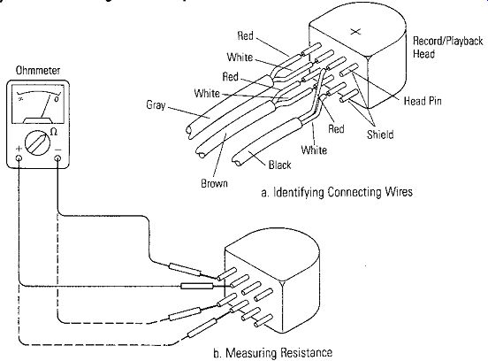
Figure 6-14. Checking Record/Playback Head
The Amplifier
• POWER OUTPUT
The most common measurements of an audio amplifier are power output and frequency response. These tests can be made with a VOM since they involve basic voltage, current, and resistance measurements. Both power output and frequency response of an amplifier can be measured by the circuit interconnections shown in Figure 6-15. The input signal to the record amplifier is provided by the output of an audio oscillator connected through a plug into the microphone jack. As an alternate, an audio test tape may be used for the source of the test signal. The value of R connected across the shielded cable from the external speaker jack (or there may be an auxiliary output connection (or jack) on the back of the unit) should be equal to the rated output impedance of the amplifier (usually 4 or 8 ohms). The output power of the amplifier is proportional to the RMS voltage measured across the load resistor, in accordance with the power equation:
p = V2_output / R
The audio oscillator should provide a good sine waveform output of uniform amplitude. Also, the amplifier must not distort the sine wave if the measurement is to be accurate. An approximate indication of whether the output signal is being "clipped" or distorted may be determined by observing the meter of the output. As the input signal is smoothly increased, the output voltage (and consequently power) will increase at the same smooth rate until clipping occurs. A reduced rate of increase in output voltage indicates that the amplifier output is being overdriven and the output waveform distorted. Now, reduce the level of the amplifier's input (the audio oscillator's output) to a convenient value - about one half the level that caused clipping of the output voltage.
• Frequency Response
The frequency response of the tape recorder's audio amplifier can be measured with the same test circuit of Figure 6-15. A typical frequency response curve (or graph) is shown in Figure 6-16. Note that the frequency response cannot be checked accurately unless the tone controls are first set to mid-range. To measure the output signal from the amplifier you should use the scale on the voltmeter calibrated in decibels. Use an input signal level V,00 measured with the meter as shown, that is below the one-half level so the output waveform will not be clipped. Change the range on the meter reading the output level so that it reads near mid range.
Set the frequency of the audio oscillator to 1,000 cycles per second (Hertz). Using the voltmeter measuring V_output adjust the volume control until the meter reads O db on the decibel scale. Both meters measuring V_input and V _output must be meters that have a frequency response of their own of up to 20,000 Hertz. Do not change the volume control or tone control settings.
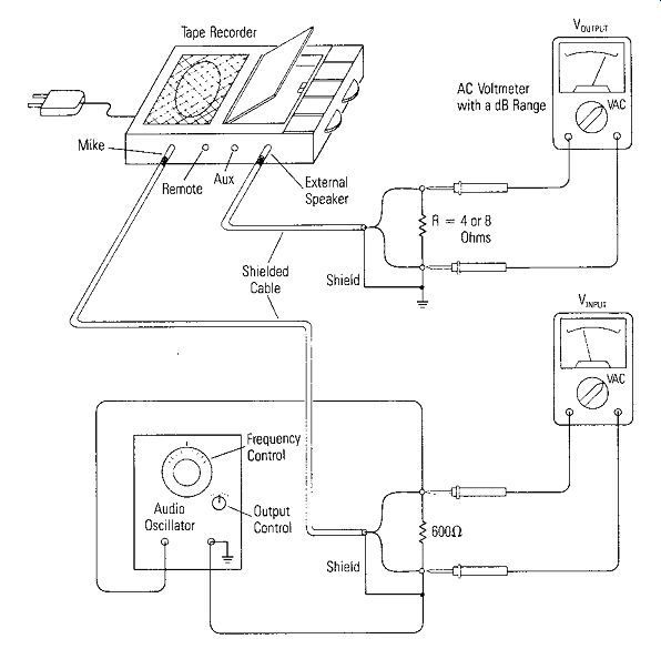
Figure 6-15. Circuit Arrangement for Measurement of Frequency Response
Change the frequency of the oscillator to 2,000 Hertz. Make sure V_input is constant and measure V_output on the decibel scale. Plot the result on a frequency response plot shown in Figure 6-16. For 2,000 Hertz the reading in Figure 6-16 is still 0 db.
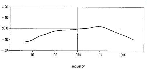
Figure 6-16. Typical Frequency Response of a Tape Recorder/Player
Increase the frequency of the oscillator in 2,000 Hertz steps, measuring V_input to make sure it remains constant at each step, and plot V_output in decibels at each step on the frequency response of Figure 6-16. Most audio systems have good response (within 3 db) at least to 15,000 Hertz. Measurements can be made up to 100,000 Hertz if the meters have frequency responses to respond to such a high frequency.
After the frequency response above 1,000 cycles has been measured, reduce the oscillator frequency in 100 or 50 Hertz steps from 1,000 Hertz and measure V_input at each step (on the decibel scale) until the frequency is 10 Hertz. A typical response should look like Figure 6-16. The measurements and initial calibration point was started at 1.000 Hertz because that point is usually always within the flat frequency response of any audio system. To say that an amplifier has a "flat" frequency response means that all frequencies are amplified with equal emphasis and the frequency response curve would be ideally, a horizontal foe.
If one wants to determine the effect of tone controls, the frequency response measurements can be repeated with the tone controls set at the two extremes.
Troubleshooting the Amplifier
The amplifier in the cassette recorder/player is a semiconductor amplifier. It may be built of discrete components or it may be one or two integrated circuits. If it is a completely contained integrated circuit, it will be difficult to troubleshoot for a problem unless a circuit schematic is obtained from the manufacturer. However, if it is a discrete component amplifier, then the same techniques described in the previous sections for transistor amplifiers can be used.
AUTOMOTIVE CIRCUITS
Beneath the hood of your automobile is a remarkable electrical system. This system performs several functions. It produces electrical energy, stores it, and delivers it either at low voltage, sometimes as very high current, or in high voltage surges of up to 35,000 volts. These surges occur at a rate of about 12,000 each mile and at an accuracy of about one ten-thousandth of a second. This electrical system makes your modern motorcar possible. It allows the hand crank to be replaced by the starter motor, supplies electric power for lights, which would have to be gas lanterns otherwise, and the ever increasing number of accessories like the stereo, climate control, and power windows, antenna, and door locks. A very basic, automobile electrical system was shown in Figure 3-3. It showed the major components of the system for starting the engine, and the electrical connections between them. The car frame was used as the return circuit; therefore, requiring only half as much wiring.
The car frame, when used like this, is called the electrical ground (a common connection). The battery is the heart of the system and batteries produce only de; therefore, the automotive electrical system is a direct-current system. The voltages and currents are measured with DC voltmeters and ammeters.
The Charging System
As stated, the automobile electrical system is DC. The alternator (ac generator), however, produces alternating current in its stator winding which is changed to direct current by diodes. To provide a smooth flow of current, automotive alternators are three-phase; that is they are built with three stator windings (coils) which, in effect, give overlapping pulsing of alternating current. Most automotive alternators use the Y-connected stator circuit as shown in Figure 6-17. When these pulses are rectified by the six-diode bridge, a comparatively smooth direct current is obtained. The stator windings can remain permanently connected to the battery because the diodes in the stator-to-battery circuit prevent the battery from discharging through the stator windings when the engine is not running.
When a battery is low, it will accept a lot of current, but when it is fully charged, it will take only a very small current. When an alternator is attempting to charge a battery that is fully charged, its output voltage continues to increase in order to get current through the battery. If this alternator output voltage were allowed to continually increase, the battery would be overcharged and thus ruined. The voltage regulator guards against excessively high alternator output voltage.
Electrical Checks on the Alternator
A simple check of the alternator can be made by connecting a voltmeter across the battery terminals and then starting the car. There should be three distinct readings: First, the battery voltage before starting should be about 12.6 volts. Then, while starting, it should drop to no less than 10 volts. After starting the voltage across the battery should rise to near 14 volts if the alternator is charging it. If the alternator is not charging the battery several simple checks can be made to check it.
The field coil can be "quick-checked" by bringing a screwdriver blade against the back of the alternator, in the center, and check the magnetic field strength difference with the engine off, and then running. If the field is significantly stronger with the alternator turning, the field coil is functioning properly, if not, there is no current through the field coil.
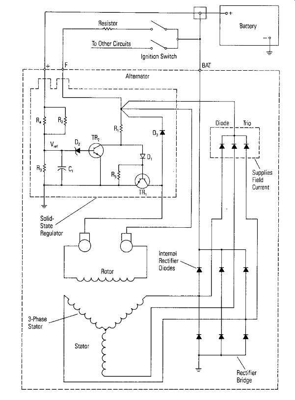
Figure 6-17. Wiring Diagram of an Alternator and Regulator
There are only three parts to check if an alternator fails to produce any output: the stator, the rotor windings and circuit, and the diodes and circuit. These are tests to be made with the alternator on the bench.
1. Testing the Rotor Field Coil: A good check of the field coil is a "current draw" test.
Use your VOM/DVM as an ammeter on its high current range and connect it between the F terminal and the battery. Slowly turn the rotor by hand. The field coil current should be about 2. 5 amps at 12 volts applied. A low current draw indicates high resistance in the field circuit. This may be due to brushes not seating well on the slip rings, dirty or worn slip rings, or poor connections in the field coils. Excessive current drawn indicates a possible shorted field coil or a grounded field circuit.
An ohmmeter check can also be made of the rotor field coil. Disassemble the alternator to separate the rotor. Set the ohmmeter to Rx1 and zero the meter.
Touch the two test probes to the two rotor slip rings. The meter should read about 4 ohms. A high reading indicates a bad connection at the slip ring or a broken wire.
A lower reading indicates shorted windings.
2. Testing the Stator: disassemble the alternator, disconnect the diodes from the stator leads and, with your ohmmeter, check for a short from each lead to the stator pole frame, then check for continuity from the Y connection to all three stator leads. A short or an open on either test indicates that the stator will require replacement.
3. Testing the Diodes: with the diodes disconnected as above, and the ohmmeter zeroed on the Rx100 range, check each diode first in one direction and then in the other. Diodes should measure about 50 ohms in one direction and infinity in the other. If any diode does not, replace the diode or the rectifier assembly.
The Regulator
The regulator may be a self-contained integrated circuit amplifier with a power transistor, TR, external, or it may be a discrete component amplifier. If it is a discrete component amplifier, it can be checked using the techniques described previously for semiconductor amplifiers. TR, supplies current to the rotor (field) to regulate the output of the alternator. The voltage, V'"" is compared to the zener diode voltage of D, to cause TR,. through TR,. to conduct more or less to raise or lower the alternator output. A way to check the operation of the regulator is to connect the + lead to a variable voltage source separate from the battery. As the voltage at the + terminal is varied, the alternator voltage should increase or decrease.
SUMMARY
With the completion of this section, the reader should now be able to make voltage, current and resistance measurements with a VOM or DVM in any kind of circuit and be able to determine if the circuit components are operating properly.
With good care and careful measurements, your VOM or DVM will prove to be a valuable tool for the rest of your life.