AMAZON multi-meters discounts AMAZON oscilloscope discounts
17. General Information
Wide use is made of filters in audio circuits to perform highly specialized functions. Among the simplest of such filters are those intended to isolate one amplifier stage from another to prevent de generative or regenerative coupling. Such filters are usually classed at decoupling filters.
Radio receivers and public address systems utilize filter networks for the control of tone - usually circuits which produce attenuation of either high- or low-audio frequencies. These are the familiar tone controls. In more expensive equipment, both treble and bass boost circuits may be encountered, as well as attenuation components.
High-fidelity amplifiers and speaker systems consistently make use of filters as crossover networks, i.e., arrangements in which frequencies below a predetermined value are passed on to the low frequency speaker (woofer) , while those above this limit activate the high-frequency speaker (tweeter) . Such items as presence controls, rumble filters, and scratch filters also are becoming common in hi-fi design.
In radio transmission, other types of audio filters, such as speech clippers, have become popular recently. Understanding of the function and limitations of audio filters is, therefore, extremely import ant to any technician who plans to work with, repair, or design audio-frequency equipment.
18. Decoupling Filters
When two circuits that operate at the same frequency have an impedance common to both, there is coupling between them. If the phase relationships are such as to bring the two circuits into the same phase, the coupling is regenerative and leads to possible in stability. Degenerative feedback occurs when the common impedance is between two stages in which the phase differs by 180°. The common impedance responsible for the coupling usually takes the form of a series element in the power supply. This element may be the filter choke, the filter resistor, or a voltage-dropping resistor. For example, a two-stage resistance-coupled audio amplifier has degenerative coupling through the series impedance because the plate currents in the two tubes are out-of-phase. The reasons for this may be found in an analysis of the action in the circuit shown in Fig. 19.
Consider V1 and R1 alone for a moment. If the incoming signal drives the grid of V1 negative, the tube plate current decreases and the voltage drop across R1 decreases, making the plate more positive. Any tendency of other parts of the circuit to interfere with this effect, i.e., reduce the positiveness of the plate, also reduces the amplification of the stage. Since a positive-going plate V1 causes the grid of V2 to go positive as well, the plate current of the second tube must increase, bringing about an increased voltage drop across R2, hence a more negative plate. Now, referring to the common series impedance Re in the power supply, the increased plate current in V2 causes a larger voltage drop across Re so that less plate voltage is instantaneously available for V1. Hence, the action of V2 is to reduce the positiveness of the V1 plate through the voltage drop in the common impedance. This tends to reduce the amplification of V1; the effect is, therefore, degenerative.
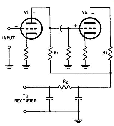
Fig. 19. Degenerative feed back or coupling between two stages of an audio
amplifier.
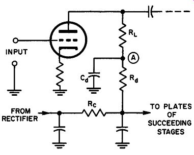
Fig. 20. The decoupling filter consists of Rd and Cd acting together.
If a third stage is added to the circuit of Fig. 19, the plate current phase relationships bring V1 and V3 into phase. The effect will be opposite to that of the two-stage amplifier: the coupling will be regenerative and may lead to serious instability in the form of self oscillation. The decoupling filter is designed to minimize such coupling and restore stability to the multistage amplifier.
The application of decoupling is shown in Figure 20. V is the first of the three amplifier stages, RL is the normal load resistance, Rd is the decoupling resistance, and Cd is the decoupling capacitance.
Such a filter maintains the voltage at point A constant regardless of the variations in the voltage drop produced across Re by the following stages. In this way, the fluctuations in plate voltage that might cause degenerative or regenerative feedback are eliminated or minimized.
If the reactance of Cd at any frequency to which the amplifier is expected to respond is substantially less than Rd plus Re, the decoupling is effective. The factor by which the undesirable coupling is reduced is given by:

(19)
… where Xe is the reactance of the decoupling capacitor, ~ is the resistance of the decoupling resistor, and Re is the resistance of the common impedance in the power supply. In most decoupling filters, Rd is generally made about 1/5 the value of the load resistor while Cd is seldom less than 8 to 10 µf. A decoupling circuit also acts to reduce hum since it appears as an additional power supply filter section.
19. Tone Control Considerations
An ideal audio-amplifier system, encompassing the input transducer, the amplifier itself, and the final reproduction device, must have a frequency response that is linear and level over the whole audio spectrum. Since pickup devices such as microphones, phono graph cartridges, phototubes, photocells, and other transducers seldom have the desired linearity, it is often best to control the frequency response of the amplifier proper so as to compensate for these defects. Reproducers, such as loudspeakers, also contribute to the need for frequency compensation.
Telephone engineers, broadcast and television designers, and recording engineers make use of highly complex electrical networks for frequency compensation. Comparatively simple combinations of resistance, capacitance, and inductance, however, are more than adequate for the usual applications; we are confining our discussion to these simpler forms.
Basic tone compensation arrangements may be divided into two classes: resonant and nonresonant circuits. Such circuits are not confined to simple tone control applications in audio amplifier work, they are also in speech clippers, crossover networks, presence controls, rumble filters, scratch filters, et. al.
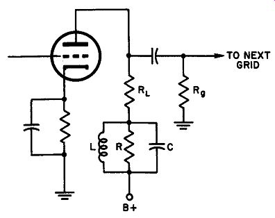
Fig. 21. Resonant tone compensation circuit as part of amplifier plate load.
Such a circuit provides either treble or bass boost depending up on the frequency
chosen for resonance.
20. Resonant Tone Compensation
In general, a resonant tone control comprises an inductance and capacitance which resonate at a preselected frequency, and a resistance used for damping, or reducing the Q of the resonant pair.
These circuits are connected as either the plate load of an amplifier or the grid load of the amplifier following. In Figure 21, a resonant tone control is shown in the plate circuit of the first amplifier tube.
The filter circuit is designed to provide bass boost; that is, the re sonant frequency is adjusted near 100 hz to pick up the normal drooping of amplifier response at the low frequencies.
Three different response curves are given in Figure 22. These are the result of selecting different values of damping resistor (R) in each case, depending upon the extent of bass boost desired, damping increases, of course, as R is made smaller.
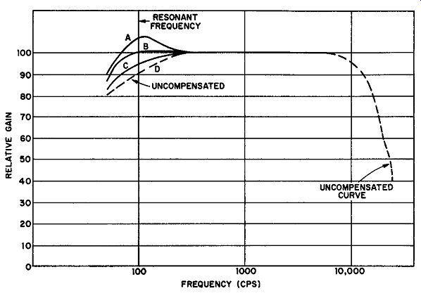
Fig. 22. A resonant base boast filter. Curve A, shows the undamped frequency
response (R omitted), B, a medium amount of damping, and C, a highly damped
response.
The increase of gain at the resonant frequency of the filter is appreciable only when RL is much smaller than the plate resistance of the tube and R1 in parallel. A resonant filter of this type is most effective when used in the plate circuit of a pentode amplifier since this tube has an extremely high plate resistance.
All simple methods of resonant tone control have an effect on the volume of the reproduced audio. These circuits attenuate certain frequencies, though they are often referred to as boost circuits. The maximum gain at any frequency must always be less than the maximum gain of the same amplifier under normal conditions obtained for resistance coupling.
21. Nonresonant Tone Compensation
Although nonresonant tone control circuits using inductances are encountered, they are unpopular as inductance costs are high, undesirable resonance of the inductor with stray capacitance often brings peaks of response at undesirable points, and inductances are often responsible for hum due to stray pickup. Most nonresonant compensation circuits use only resistors and capacitors.
Figure 23 represents one of the most successful modern R-C tone compensation circuits, found in many high-fidelity kits and factory wired audio amplifiers, and available in printed circuits (shown inside dashes). As it is a modified bridged-T compensation network, its analysis requires specialized mathematical treatment which is not attempted here. A qualitative description of its operation can be briefly presented, however.
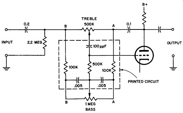
Fig. 23. A prevalent form of tone compensation network providing for bass
and treble boost and attenuation. The section inside the dashed lines is generally
in the form of a printed circuit.
The 0.1 µf capacitor from the plate of the amplifier tube is a source of negative feedback. Since its reactance is small even for low-audio frequencies, the entire audio range is fed back to terminal A of the filter network.
When the two potentiometers (treble and bass) are centered, the phase relationships for both ranges result in a flat response (i.e., treble and bass portions of the signal are applied to the amplifier grid from the input with neither attenuation nor boost) . As either control is shifted from its central position, the input and feedback phases are shifted so that either attenuation or boost occurs, depending upon the direction of wiper motion. For example, when the treble control wiper is moved all the way to the left (to point B) , full treble boost is obtained. The phase relationships between input and fed-back voltages increase the treble response. When the wiper is rotated to point A, the fed-back voltage tends to cancel the trebles, providing full attenuation. Similarly, the bass-control potentiometer in position B provides full boost, while in position A it provides bass attenuation. Obviously, great care must be taken in the design of such a network, particularly for boost purposes, because the in-phase condition of the input and fed-back voltages tend to produce instability.
In less elaborate equipment, simpler methods are usually employed for attenuation of bass, treble, or both. The treble range may be controlled by shunting the plate circuit of a tube by a capacitance in series with a tone-control potentiometer (Fig. 24) . With the tone control resistance at maximum, very little high-frequency shunting takes place since the impedance of the series components (C and R) is high, even for the high frequencies. As the resistance is decreased, more and more shunting occurs, starting with the highest frequencies and working down toward the lower ones.
A measure of control is established, permitting the operator to select the frequency at which attenuation begins to become audible.
Bass attenuation in similar equipment usually takes one or more of three forms. The capacitance of the grid coupling capacitor is reduced to present higher coupling impedance to the bass range.
The capacitance of the cathode by-pass capacitor is reduced in any amplifier stage to provide a limited amount of bass attenuation. The capacitance of the screen by-pass capacitor is reduced to provide bass attenuation, particularly when the screen supply current is fed to the tube through a high value of dropping resistor.
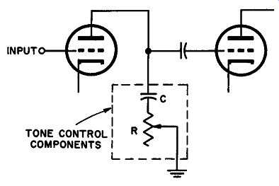
Fig. 24. Simple tone control system found In Inexpensive audio equipment.
22. Speech Clipping
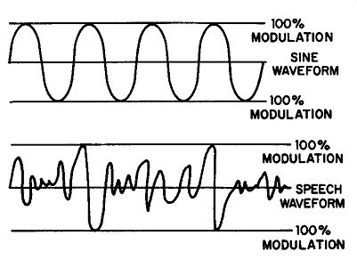
Fig. 25. Speech waveforms and sine waves compared for power content. The power
present In a sine wave averages much more than a speech wave because it reaches
peak value In every cycle.
In the transmission of radiotelephone signals involving only speech waveforms, an amplitude-modulated radio-frequency carrier carries the modulation power in its sidebands, the percentage modulation being determined by the relative peak amplitudes present in the speech waveform. Unfortunately, the average power content in a speech waveform is quite low when compared to a sine wave. As shown in Fig. 25, a sine wave reaches peak value during every cycle, but a speech wave does this only occasionally. Yet both waveforms represent the conditions for 100% modulation of a given r-f amplifier as the peak values are the same.
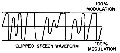
Fig. 26. The speech wave form of Fig. 25 amplified to approach power content
of sine wove but clipped to prevent overmodulation.
It is possible to increase the modulator power in either the speech amplifier system or modulator itself so that the power content begins to approach the sine wave value. If, at the same time, all peaks producing overmodulation are clipped at the 100% point (Fig. 26), overmodulation cannot occur due to excessive peak values. however, clipping produces many rectangular peaks having the same high-order harmonics as produced by overmodulation, so that a signal clipped in this manner tends to splatter, or occupy too-wide a slice of the r-f spectrum. This is prevented by filtering all audio frequencies not needed for intelligibility of speech after clipping, before modulation is applied to the output amplifier. In general, intelligibility does not suffer seriously if such a filter does not attenuate any frequencies below 2500 cycles per second, and splatter is minimized if attenuation is high for all frequencies above 3000 hz.
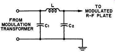
Fig. 27. Splatter filter far high level use between the modulator output and
the modulated amplifier.
Splatter filters (Fig. 27) are generally made up of a single inductor and two equal-value capacitors selected in accordance with equations (20) and (21). These equations are based upon a cut off frequency of 2500 hz.
(20) (21)
… in which L is the choke inductance in henries, C1 and C2 are equal value capacitors in mfd., and R is the modulating impedance of r-f power amplifier being modulated.
Example: Find the filter component values for a 2500 hz cutoff splatter filter used between a class B modulator and an r-f amplifier operating at 1000 volts (plate voltage) 150 ma plate current.
Solution: Since the plate voltage and plate current of the r-f amplifier determine its operating impedance, this is first determined:
In practice, of course, the capacitor value would be selected as .01 µf and the value of the choke adjusted accordingly to realize a cutoff frequency of 2500 hz.
23. Crossover Networks
The most effective way of overcoming the inherent loss of volume at high and low-audio frequencies on most speakers, is the use of two or three separate units.
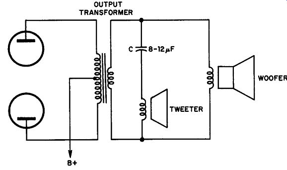
Fig. 28. Simplest configuration for frequency divider or crossover network
designed to find high- and low-frequency loudspeakers.
In a two-speaker system, one unit is specifically designed for good high-frequency response, the other for good low-frequency response.
The speaker cone moving in and out along the distance necessary to pump high-level, low-frequency sound into the listening area, can not move fast enough to reproduce the high frequencies properly. Similarly, the vibrating element of a "tweeter", or high-frequency speaker must be small and light, hence the distance covered on low frequency excursions is too small for effective reproduction of this range. Should two such speakers be connected to an amplifier without special precautions, each one attempts to do the other's job with the result that serious losses occur, as well as distortion.
The simplest form of filter network directing the highs and lows to the corresponding speaker is shown in Fig. 28. In this arrangement, a large value of capacitance is connected in series with the tweeter while the woofer or low-frequency speaker shunts the out-put transformer directly. The capacitance required depends upon the desired response characteristics and the impedances of the two speakers. High frequencies are shunted through the tweeter unit since the capacitive reactance of C at these frequencies is relatively low. Low frequencies appear as power in the voice coil of the woofer as the inductive reactance of the voice coil is considerably lower for the low frequencies than for the highs, making it possible for low-frequency currents to flow through this voice coil with little impedance. This simple arrangement is not as satisfactory as circuits that utilize inductors and capacitors.
Figure 29 illustrates a basic, high-performance two-speaker cross over network. In the design of such a network, the crossover frequency is first selected (usually from 400 hz to 1000 hz) and then the components chosen so that resonance is obtained at the crossover frequency. L1 and C2 constitute a series resonant circuit at the crossover frequency, so do L2 and C1. The constants given in Fig. 24 were selected for a crossover frequency of approximately 450 hz, using speakers with 8-ohm voice coil impedances.
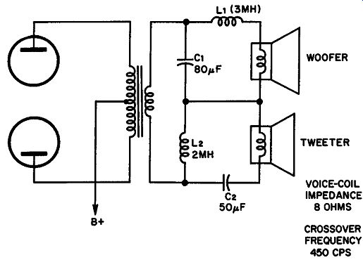
Fig. 29. An L-C two-speaker crossover network with resonant elements.
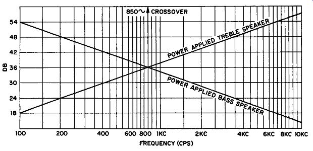
Fig. 30. Idealized response of a two-speaker, 850 hz crossover network with
a total sound power input of 72 db. (Electronic Experimenters Handbook, 1958).
At the crossover frequency the voltages available across the speaker source components (C1 and L2) are equal, as these units are in resonance. The impedance match at the crossover frequency is maintained substantially constant by action of the series resonant circuit containing L1, C2, and the two voice-coil windings. At high frequencies the voltage drop across C1 becomes small, while the drop across L2 increases, bringing the tweeter into play. The opposite occurs at low frequencies.
An idealized response characteristic for a two-speaker crossover network is shown in Fig. 30. The crossover frequency is 850 hz.
The total available sound energy is 72 db. At the crossover frequency half the total energy is applied to each speaker. At other frequencies the proportion varies, one speaker getting less power, the other speaker more, but the sum of 72 db is constant.
A frequency division network for a three-speaker system is given in Fig. 31. The same general rules apply to the selection of these components. Most crossover networks are primarily designed for resonance, as described, and are then adjusted experimentally to match the speakers used as well as the wishes of the listener.
24. Presence Control
This is the filter system in audio-frequency reproduction in which the middle range of frequencies is accentuated. Since the human voice operates essentially in the mid-range frequencies, increased mid-range emphasis for vocal performances lends realism to the reproduction and an increased sense of presence to the vocalist.
A presence control is usually inserted between the preamplifier and power amplifier section of the system. Since it has an insertion loss, the system should have a reserve of gain of at least 12 db. Since most amplifiers are operated conservatively, this reserve is generally available.
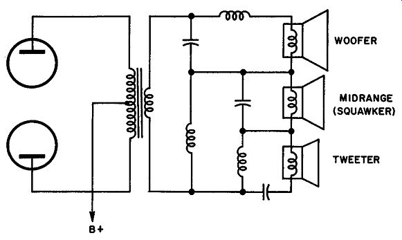
Fig. 31. Three-speaker crossover network. Exact values of components are generally
obtained experimentally, although approximate values are determined from resonance
considerations.
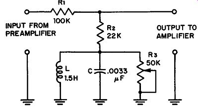
Fig. 32. A practical presence control circuit. The extent of presence is governed
by R3.
A practical circuit for a presence control appears in Fig. 32. An accentuation of 6 db occurs at approximately 2500 hz. Since tastes vary as to the extent and frequency of presence, other frequencies may be obtained by varying C, and additional accentuation may be realized by increasing the resistance of R3.
The circuit action is easy to see. L and C form a parallel-resonant circuit and are selected to resonate at the center presence frequency.
The frequencies in the vicinity of 2500 hz are accentuated because the voltage drop across the L-C combination is greatest in this region. With the wiper of R3 at the ground end of the potentiometer, full accentuation occurs. When moved to the upper end, the resonant circuit is shorted out so that the shunt load becomes merely R2.
This produces zero accentuation, but accounts for the insertion loss.
25. Rumble and Scratch Filters
Fig. 33. A combination rumble and scratch filter designed to minimize noise from defective turntables, low-speed and high-speed records.
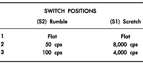
Phonograph turntables sometimes develop voltages at the input of high-gain amplifiers that produce rumbles in the output, at frequencies that may range from 20 hz to 100 hz. A filter designed to eliminate this sound, called a rumble filter, is a high-pass arrangement having a cut-off frequency in the 20 to 100 hz range. Usually, the cutoff point is made adjustable, either by the continuous action of a potentiometer or by a step switch used to select predetermined values of capacitance or inductance (Fig. 33) . Phonographs also suffer from noise voltages due to the scratch of the stylus on the disc. For 33-1/3 rpm long-play records, this scratch develops after long use and takes the form of a hiss at about 8000 hz. Older 78 rpm records have an inherent scratch at approximately 4000 hz, even when they are new. The scratch intensifies with repeated usage and produces frequencies of high amplitude even below this figure. In Fig. 33, the scratch filter consists of S1 and its associated resistors, capacitors, and inductors while S2 with the associated resistors and capacitors is the rumble filter. Table I provides information on the cutoff frequencies in the various switch positions.
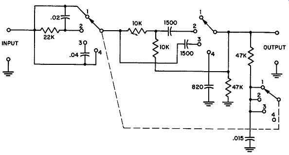
Fig. 34. Turnover and roll-off filter for equalizing any recording to match
the RIAA response of modern amplifiers. The filter accomplishes this adding
or subtracting from the standard RIAA curve.
The attenuation rate is approximately 12 db per octave. Thus, if the scratch filter switch (S1) is set for attenuation at 4000 hz, the response of the filter will be relatively flat up to this frequency, whereas at 8000 hz the scratch will be reduced by about 4 to 1. The rumble filter would be used on the No. 2 position of S2 for very low frequency rumble (50 hz) and on No. 3 position for rumble of frequencies in the vicinity of 100 hz.
TABLE 1 SWITCH POSITIONS
(S2) Rumble | (S1) Scratch
26. High Fidelity Equalizer
Before 1953, standards were not established for record equalization curves. Record manufacturers adopted individual response patterns according to their own lights, so that any amplifier had to be equipped with many equalization settings. All records made after 1953, are standardized in accordance with the specifications of the Record Industry Association of America (RIAA) . (This response is called Orthophonic by RCA and associated companies). Many people own excellent recordings made before 1953. To render these properly, the standard RIAA response can be modified by a filter network as illustrated in Fig. 34. Provisions have been made in the design of this circuit to incorporate four positions of low-frequency equalization (often called turnover) and four positions of high-frequency equalization (de-emphasis or roll-off). Since the two selector switches operate independently, the filter can produce 16 different equalization settings so that it accommodates virtually any recording.
The insertion loss of the network is about 6 db. For reasons given previously, this is easily offset by any modem amplifier's reserve gain.
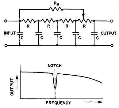
Fig. 35. A resistance-capacitance notching filter that provides sharp attenuation
of one frequency.
27. Scott Filter
An R-C filter for small currents that notches the audio response of an amplifier system is shown in Fig. 35. Designed by H. H. Scott in 1939, the filter system bears his name and is claimed to provide almost complete attenuation at any desired frequency. For example, the Scott filter may be nicely applied for the removal of scratch noise that peaks at 8000 hz, such as the hiss that develops in the older of LP records; it is quite effective for minimizing 78-rpm scratch at 4000 hz and the surrounding frequencies.
The action of the Scott filter depends upon feedback of one frequency to the input 180° out of phase with the incoming signal.
The capacitors and resistors are all of the same values except Ra.
By selecting them carefully, the phase of the input signal can be inverted 180° by the R-C pairs for the frequency to be notched from the response. Further fine control is provided by adjusting the tap on the last resistor. Since the final values of the R and C components depend upon the input and output impedances, as well as the frequency to be notched, design formulae are not easily provided.
A typical response curve is given in the insert in Fig. 35. Note that the Scott filter does attenuate frequencies higher than the notched frequency but the extent of the attenuation is small, and in most cases is barely noticeable.
28. QUIZ
1. What is the function of a decoupling filter?
2. Under what conditions are decoupling filters required? Draw an amplifier circuit consisting of three stages of amplification, showing a practical de-coupling network.
3. Explain, with the aid of diagrams, how a resonant tone control filter operates.
4. What are the underlying principles of nonresonant tone compensation systems?
5. Draw a two-stage amplifier circuit showing a simple type of tone control. Explain its operation.
6. Explain the advantages of speech-clipping in the transmission of speech by radiotelephone. Why can't clipping be used in the transmission of music?
7. Why are crossover networks used in high-fidelity sound reproduction? Draw a diagram showing the basic principles of two-speaker crossover networks.
8. Determine the values necessary to make up a speech-clipper splatter filter having a cutoff at 3000 hz, the filter being placed between the modulator and an r-f amplifier operating at 1500 volts (plate) and 200 ma.
9. Distinguish between the following filters in terms of function and frequencies affected: (a) roll-off filter, (b) presence control, (c) turnover filter, (d) rumble filter, (e) scratch filter, (f) curve equalizer.
10. Explain the operation of the Scott notching filter. Use a diagram to help.