AMAZON multi-meters discounts AMAZON oscilloscope discounts
29. The Need for Video Filters
Equipment for transmitting and receiving signals containing video components, as in television and radar, must meet certain requirements. The amplifiers must respond to frequencies lying within an extended range, the lower limit approximately equal to the frame repetition rate in television, the upper limit at least one-half the rate of transmitting picture elements. In American television practice, these limits are 30 hz and approximately 4,000,000 hz. Amplifiers must pass components within this frequency range with a minimum of amplitude distortion and time-delay discrimination.
A standard R-C coupled amplifier tends to favor the middle-range of frequencies, discriminating against the highs and lows. Shunt capacitances consisting of input and output capacitances reduce the high-frequency gain. Similarly, series impedances such as the coupling capacitor cause a diminution of low-frequency gain. Particularly at low frequencies, the phase response (time-delay characteristics) of an uncompensated amplifier may be quite troublesome. The reason is that a very small phase shift in the amplifier circuit measured in degrees is a very large time delay in seconds when the frequency is low. [1 ]
Thus, for extended frequency range coverage, an uncompensated amplifier is unsatisfactory. Although frequency compensation circuits are not ordinarily viewed as filters, their selective behavior earns them a brief discussion in this guide.
[1. Schure, A., Video Amplifiers. New York, John F. Rider Publisher, Inc., 1959]
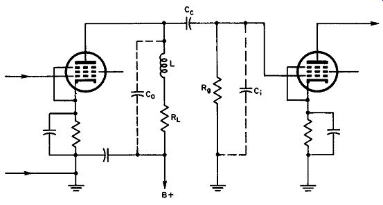
Fig. 36. Fundamental R-C video amplifier showing the position of the shunt
peaking coil L1. Co and C, are tube and stray capacitance which are referred
to as C, in the text.
30. High-Frequency Compensation - Shunt Peaking
The principal cause of loss of gain at high frequencies is the shunting effect of tube and stray capacitances going into C0 and C1 in Fig. 36. Taken together the total shunting capacitance is referred to as Ct. If a coil having the proper inductance L, is connected in series with the load resistor RL, a substantial improvement can he affected in the response curve, the high-frequency gain being boosted to an extent determined by the inductance L and Q of the shunt peaking coil. In practice, the inductance of the coil is calculated first from equation (22) and then trimmed until the desired response is obtained.
(22)
in which Ct = C0 + C1
… and RL is plate load resistance of the first amplifier tube. Ct is best found by measurement, although it may be calculated from the known capacitances with corrections for the Miller effect.
When L1 is obtained from equation (22), the resonant frequency for this coil and Ct is 1.414 times as great as the highest frequency to he amplified in the video range. For validity, the value of RL used in equation (22) should he found from:

(23)
…. in which f0 is the highest frequency to he amplified. For these conditions, the values of RL and L1 are fixed. Other values may be used with success but the ones obtained this way represent a good compromise between linearity of amplitude response and available gain from the amplifier.
31. High-Frequency Compensation - Series Peaking
Another method of high-frequency compensation which gives higher and more linear phase response is shown in Fig. 37. The filter element consists of output capacitance C0 , the following input impedance C1 , and the coupling inductance L which isolates C0 from C1. The filter is terminated at the point of entry by impedance RL and at the remote end by Rg. The effect of the coupling capacitor Ce may be ignored since it is effectively a short-circuit at high frequency.
The value of the filter coil and the plate load resistance is determined first by measuring capacitances C0 and C1 to determine Ct.
Then L is determined for a given high-frequency limit, f0 , by equation (24). L (24)
This equation is obtained because the resonant frequency of L and C0 is chosen 1.41 times as great as f0. The plate load resistance is selected on the basis of equation (25).

(25)
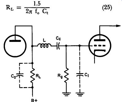
Fig. 37. Series peaking system involving the use of a series peaking coil
between the plate of the first amplifier and the coupling capacitor to the
next amplifier.
32. High-Frequency Compensation - Combination Peaking
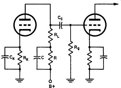
Fig. 38. A low-frequency compensation filter that improves amplitude and phase
response.
Equation (23) shows that the load resistance for the first amplifier tube (RL) must be made equal to the reactance of Ct for effective action at the highest frequency for which compensation is to he obtained. Equation (25) indicates why the gain of the series peaking method of compensation is greater: the value of RL may he made 1.5 times as great as the reactance of C1, increasing the gain of the stage. When both series and shunt peaking are used together, a further increase of gain can he realized because, as analysis now shows, RL can be raised in value to 1.8 times the reactance of Ct. The design equations for combination peaking are:

(27)
(28)
33. Low-Frequency Compensation Filter
At low frequencies, the shunt capacitance Ct has a very high reactance so that its effect is negligible. The increasing reactances of the coupling and by-pass capacitors as 30 hz is approached, however, begin to introduce amplitude and phase distortion. Impractically large values of coupling capacitance and grid resistance are required for proper performance of the amplifier at frequencies in this low range. Should these be employed, the high-frequency response suffers and the amplifier tends to he unstable, often producing relaxation oscillations or motorboating.
It is customary to use a low-frequency compensation filter in series with the output resistor RL as illustrated in Fig. 38. This combination produces a phase shift that compensates for the time delay introduced by coupling components Cc and R1, and acts as a decoupling filter, preventing the amplified signal from developing a voltage drop across the power supply impedance, thus discouraging instability.
In practice, R is often made as large as possible without causing an uneconomical reduction of plate voltage; then the value of C is selected to provide effective decoupling without producing oscillation.
It also turns out that the low-frequency response of an amplifier is affected by the cathode impedance, Rk Ck. If this is a serious factor, the decoupling filter may be designed in accordance with equations (29) and (30). With values obtained this way, the cathode reactance will be cancelled out as a source of low-frequency distortion. The filter will continue to serve in its decoupling role.
Rf = Rk gm RL (29)
(30) in which gm = transconductance of the first tube and RL is the plate load resistor. Rk and Ck are the cathode components shown in Fig. 38.
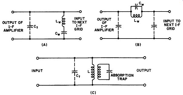
Fig. 39. (A) Series resonant wave trap shunts the grid-Input circuit (b) Parallel
resonant circuit Is In series with following grid circuit. (C) Absorption trap
is not connected In the circuit electrically.
34. Reflection Filters
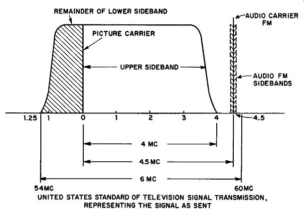
Fig. 40. American standard television channel used as a basis of transmissions
In this country. This is actually the transmitter output curve.
In television signal reception, the sound tends to produce voltages that disturb the picture. So does the sound in the lower adjacent channel, but not to the same degree.
Both types of picture interference are eliminated by rejection filters or wave traps. Various types of filters have been used with success. Among the simplest are the parallel-resonant type, series resonant type, and the absorption trap (Fig. 39) . In the series resonant filter, Lw and Cw are tuned to the rejection frequency. All voltages of this frequency find the shunt path through the series-resonant circuit a very low impedance, so rejection-frequency voltages cannot develop between the grid and cathode of the succeeding stage. The parallel-resonant circuit (Fig. 39B) presents a high impedance to the rejection frequency, causing the major voltage drop to occur across the trap rather than at the grid of the following i-f amplifier. Absorption traps such as that in (C) are normally employed when the i-f amplifier plate-load impedance is a single tuned circuit (L) . The trap is tuned to the undesired frequency and is inductively coupled to the plate-load coil. Due to the very high Q of the trap circuit, most of the energy present in the tuned circuit is passed on to the trap, reducing the Q of the tuned i-f coil at the resonant frequency. This decreases the gain of the stage enough at the rejection frequency to remove the undesired signal from the picture circuits.
35. Sideband Suppression Filters in Television
Normal amplitude modulation, such as that used in video modulation of the television carrier, always results in two sidebands, one above and one below the carrier. Since the signal components in the two sidebands contain the identical information, the double sideband system of transmission is wasteful of spectrum space. In view of this, standard television transmission practice now uses a system called vestigial sideband operation, in which the lower side band components are partially removed. Removal of the lower side band, theoretically more economical than vestigial sideband operation, is impractical because it presents severe technical problems.
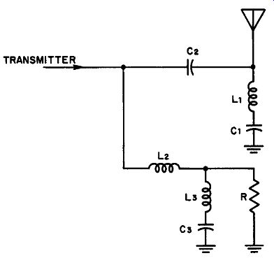
Fig. 41. Vestigial sideband filter shown with lumped constant elements rather
than a, sections of coaxial trans mission line.
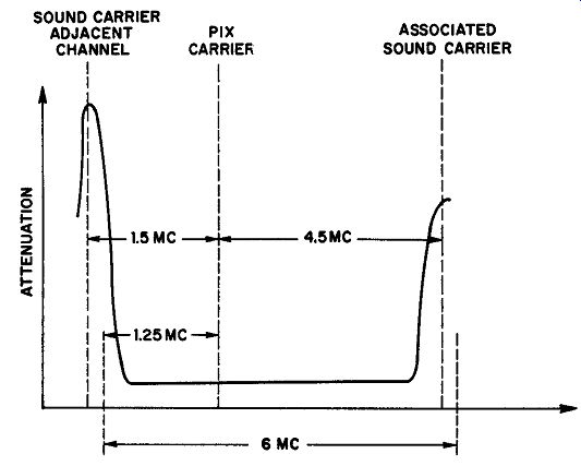
Fig. 42. Attenuation characteristics of the vestigial sideband filter Illustrated
in Fig. 41. This prevents the production of an output waveform that meets U.S.
standards.
The band-elimination filter, used does not have ideal cutoff characteristics, and attempting to remove all the components of the undesired sideband inevitably results in phase shifts. Vestigial side band operation compromises by completely removing the unwanted components only at a relatively great frequency separation from the carrier. Adjacent to the carrier, the unwanted frequency components are left undisturbed.
The band-rejection filter required to produce the output curve shown in Fig. 40 must have attenuation characteristics like those shown in Fig. 42. In practice the elements of such a filter are made up of segments of coaxial transmission lines. Figure 41 shows the filter sections as containing lumped constants to facilitate analysis.
The upper branch of this two branch filter contains C2, L1, and C1. C2 represents a low impedance path for the high-frequency sideband which passes on to the antenna. L1 and C1 comprise a series resonant circuit, which aids in obtaining the flat-topped, sharp edged pass-band shown in Fig. 40. The lower branch consisting of L2, L3, and C3 passes the undesired low-frequency components to the dissipative resistor R where the power is converted into heat.
L3 and C3 form a series-resonant circuit which shapes the output waveform to conform with American standards.
36. QUIZ
1. Explain why a standard resistance-capacitance coupled oscillator reproduces high and low frequencies poorly.
2. Describe the operation of a shunt peaking coil as used in the video amplifier in a television receiver.
3. Assume that the highest frequency to be amplified in a video amplifier is 4.0 me, and that the total shunt capacitance is 8.5 µµf. Find: (a) a suitable value of load resistor to use for shunt peaking this amplifier. (b) the inductance of the shunt peaking coil required.
4. Describe how you would go about measuring input and output capacitances in a video amplifier.
5. Using the figures in question S, calculate the value of series peaking coil required to provide uniform amplification up to 4.0 mhz.
6. Determine the load resistance that would best suit the series peaking coil of question 5.
7. A television monitor contains a video amplifier that must provide uniform amplification up to 6.0 me. Its input capacitance is 3.6 µµf and its output capacitance is 3.2 µuf. (a) Which compensation method would you use? Why? (b) Determine the values of all components required to compensate the amplifier properly.
8. What are the two functions of a low-frequency compensation filter such as that given in Fig. 38. How are these functions realized?
9. Draw diagrams illustrating three types of rejection filters or traps used in television. With the aid of these diagrams explain how the traps operate.
10. How does the band-rejection filter of Fig. 41 accomplish the desired objective?