AMAZON multi-meters discounts AMAZON oscilloscope discounts
23. Space Waves
To distinguish it from the ground wave and sky wave, propagation in the lowest region of the Earth's atmosphere is often called tropospheric propagation or space wave propagation. This type of wave transmission relies on neither ground currents nor ionospheric refraction or reflection. It is the wave used in "line of sight" communication (when transmitting and receiving antennas are within sight of one another). The space wave commonly consists of two components: the direct ray and the ground reflected ray, as illustrated in Fig. 16A. If the antennas are sufficiently close to each other, both of these rays usually reach the receiving antenna, although in different proportions. The ground reflected ray is usually the weaker of the two because of the losses suffered during reflection from the earth.

Fig. 16. (A) The direct and reflected ray components of the space wave. (B)
The shadow zone.
The direct ray suffers about the same attenuation as a wave in free space. At the receiving antenna, the total signal is the vector sum of these two components.
The transmitting and receiving antennas are usually quite far apart in relation to their elevation above the ground, so that the length of the path of the reflected ray deviates little from that of the direct ray. The reflected wave suffers a 180-degree phase shift when it rebounds from the ground, and so (neglecting earth losses during reflection), if the two rays traveled the same distance, they would add vectorially to zero, resulting in complete cancellation at the receiving antenna.
Fortunately, the reflected ray does travel a slightly greater distance, hence the net phase difference at the receiving antenna is never 180 degrees. In this idealized case, the actual phase difference is determined purely by the path difference in terms of wavelength, not linear units. In other words, the net signal received under these conditions is dependent largely upon the frequency used.
For example, if the wavelength of operation is 360 meters, and if the path difference is 2 meters, the phase shift away from 180 degrees would be only 2 degrees. This would still allow a 178-degree phase differential to exist between the direct and the reflected rays, resulting in almost complete cancellation at the receiving antenna. If, however, the wavelength of operation is 4 meters, the same 2 meters of path difference would produce a phase difference of 180 degrees, completely cancelling the reflective phase shift of 180 degrees. The two rays would, in this case, add algebraically at the receiving antenna and result in a signal nearly double the strength of either ray.
It should be clear from the above that at low frequencies, the space wave is of little use because of this cancellation; only at higher frequencies where the path difference becomes a significant proportion of the wavelength used does the space wave become an important means of communication. Above 30 mhz, where the ground wave is quickly attenuated and the sky wave is not returned to earth, the space wave is often the only means of communication between two points.
24. The Radio Horizon
The theoretical conditions presented above are usually complicated by practical limitations. For instance, the earth is not a perfect conductor, hence some of the ground reflected signal is lost in the process of reflection. For the same reason, the phase shift of reflection is never exactly 180 degrees. In addition, the curvature of the earth causes the reflected ray to change from a plane to a divergent wave. This last factor in itself is sufficient at low grazing angles to reduce significantly the reflected signal strength at the receiving antenna. Because of these losses, the total signal at the receiver is never exactly canceled, no matter what the frequency may be. Nevertheless, practical deviations from the theoretical conditions are not great enough to invalidate the conclusions drawn from the idealized example.
To lessen the received signal's dependence upon the relative phase difference of the two rays, a beam is usually formed that concentrates most of the space wave energy in the direct way. This is the job of a well designed transmitting antenna.
As a result of the earth's curvature, there exists a definite horizon to the space wave, beyond which there exists a shadow zone that cannot be reached by the direct or the ground reflected wave (Fig. 16B). Note that in the figure the radio horizon and optical horizon are not the same. Although previously the dielectric constant of free space and the atmosphere in general were taken as one, this is not strictly so. Temperature, density, pressure, and water vapor content of the air lessen as altitude is increased.
This has an effect similar to that of ionospheric free electrons; i.e., the dielectric constant is reduced with an increase of altitude. If individual rays of a plane wave travel at different altitudes (as they usually do), the higher ones will travel faster, and the wave will be refracted slightly towards the earth. The bending will vary with weather conditions and will become more pronounced as the rate of change with an increase in altitude of these atmospheric parameters increases.
25. Antenna Height
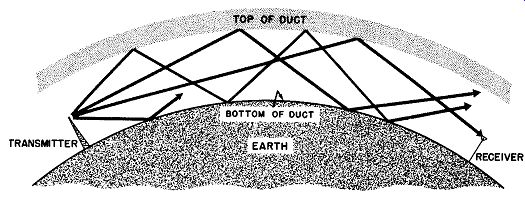
Fig. 17. Duct propagation.
It is often important to know just how far a transmitting and receiving antenna can be separated without going below the radio horizon. A simple relationship exists between the distances of separation and the height of both antennas.
(12)
Where: D=Distance in miles between receiving and transmitting antenna.
Hr = Height in feet of receiving antenna.
Ht = Height in feet of transmitting antenna
The distance from the transmitting antenna to the radio horizon can be derived by considering the radical containing Ht.
D (to horizon) = (13)
The shadow zone beyond the radio horizon, or behind a terrestrial obstruction (mountain, building, etc.) is not as sharply defined as Fig. 16B might indicate. If the receiving antenna is located behind a mountain, the field strength will decrease as the depth of the receiving antenna in the shadow increases, in terms of the wavelength of the received signal. Therefore, the line of demarcation between line-of-sight signal and shadow attenuation becomes greater as the frequency is increased (and the wavelength is decreased). The effect is clearly seen in the difference in shadow zone signal strength between television Channel 13 (210-216 mhz) and Channel 2 (54-60 mhz) . In many cases, if the terrain is rough in line-of-sight communication, the received signal strength is actually greater than it would be if the terrain were flat. This is because the rough ground scatters and partially blocks the ground reflected ray, thus avoiding phase cancellation. Even in the shadow zone, the signal strength is largely affected by the roughness of the earth. The roughness causes a diffraction of the wave down into the shadow zone. This is such an important contribution to shadow zone signal that the shadow zone is often called the diffraction zone.
26. Duct Propagations
Often there is an abnormal variation in atmospheric conditions that has a great effect on the propagation of the space wave.
Sometimes the moisture content of the air near the ground is great, but decreases rapidly with an increase in altitude. This change is usually accompanied by marked temperature variations. The effect on the dielectric constant of the air is the creation of a well defined boundary in which the rate of change of the dielectric constant is very great with a slight increase in altitude. This di electric boundary and the earth form the upper and lower walls of an atmospheric duct. Waves originating in this duct and traveling approximately horizontally are trapped, and are propagated around the curvature of the earth in a series of jumps involving earth reflection and dielectric boundary reflection. (See Fig. 17.) When this happens, one can no longer thing of space wave propagation in terms of line-of-sight and shadow zone concepts, for un der these conditions, radio waves are often propagated hundreds of miles into the shadow zone.
The action of an atmospheric duct is analogous to a metallic waveguide: there is a definite minimum frequency that may be propagated in the duct, depending on the distance between the two boundaries. The width of such ducts varies from a few feet to a few hundred feet, so that the lowest usable frequency may vary from a high of several thousand megacycles to a low of 50 to 100 mhz.
Many interrelated factors contribute to the effectiveness of duct transmission. For example, the receiving and transmitting antennas must be located within the duct. In some instances this may mean the difference of a few feet. If the receiving antenna is located outside the duct boundaries, no signal will be received, even though it may be quite strong within the duct.
27. Duct Variations
In addition to ducts found over the land which vary in height from approximately 100 to over 1500 feet, there is also a duct formed over the ocean about 50 feet from the water surface. Its vertical dimension is very small compared to the land ducts; thus, it is an almost useless waveguide for the lower frequencies, becoming important only for transmissions at frequencies well over 1000 mhz. For these very high frequencies, the transmitted energy may be carried over relatively long distances through this narrow duct.
There are a large number of varieties of atmospheric ducts.
Some of these actually focus signals when the frequency is right, while in most cases the duct behaves as a simple waveguide. Ducts may be helpful in transmission for some frequencies but may wash out other radio paths altogether. Add to this the fact that a sudden wind may destroy the efficacy of a duct that has been in existence for a long period before and it is understandable why duct propagation is inconsistent and unreliable.
Temperature inversions (a condition in which layers form so that the temperature is abnormally high in the upper regions and abnormally low in the lower regions) are more or less common occurrences particularly in coastal areas. Air from the land areas, usually comparatively hot and dry, passes over the cool, moist ocean air, forming the so-called inversion layers. The ducts formed thereby result in excellent signal transmission at frequencies from 100 mhz to 1000 mhz over paths of 100 miles or more.
28. QUIZ
(1) What is meant by "space wave" propagation?
(2) Why are space waves of little use at low frequencies?
(3) What effect does the curvature of the earth have upon the reflected ray.
(4) Explain the importance and meaning of the diffraction zone.
(5) What is an atmospheric duct?
(6) Why may duct propagation be inconsistent and unreliable?
(7) What is temperature inversion?
(8) What frequencies normally give good results for duct transmissions?
(9) Of what use arc "inversion layers"?