AMAZON multi-meters discounts AMAZON oscilloscope discounts
29. Introduction
Until quite recently, very high frequency waves have not been used in communications that involved distances in excess of line-of-sight path lengths. The vhf and uhf spectra exceed the critical frequency, hence these waves are not refracted in the ionosphere, but escape into space. Thus vhf and uh£ waves are normally propagated as space waves.
Observations made during the last war showed, however, that uh£ signals sometimes were propagated over distances considerably in excess of line-of-sight; that is, occasionally signals from high power radar sets were easily detectable well beyond the horizon with losses only slightly greater than they suffered in free space.
For the most part, these phenomena were attributed to and could be satisfactorily explained by ducting and super-refraction processes in the troposphere, in addition to diffraction effects. As research continued after World War II, however, it became apparent that the distances over which consistent rather than occasional propagation of usable signals occurred were far greater than smooth-sphere diffraction could explain, even with the help of ducts and super refraction.
In general, attenuation measurements made by research workers demonstrated the complete inadequacy of former theories in ac counting for strong beyond-the-horizon (sometimes called trans horizon) transmissions.
Many theories have been proposed to explain this phenomenon; although they differ substantially from each other in detail, in general the propagation is attributed to minute disturbances in the electrical properties of the troposphere. Precise measurements have shown that appreciable variations in the dielectric constant of the atmosphere are present as a result of turbulence, stratification and other more obscure effects, and that these variations are of the order needed to produce the observed propagation. Figure 18 illustrates the differences between distances covered by 3000-mhz waves at specific attenuations and the predicted distances that should have been covered if the propagation followed the calculations based upon smooth-sphere diffraction theory.
30. Fading
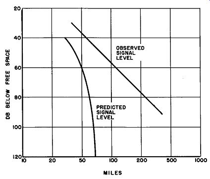
Fig. 18. Curves showing the difference between the signal level at 3000 mhz
predicted by the smooth-sphere diffraction theory and that actually observed.
The signal reaching a receiving antenna in any kind of radio transmission often exhibits a variation with time as a result of changes in the propagation medium. This effect, called fading, is evidently due to a varying instantaneous transmission loss over the radio path.
These variations in received signal intensity are conveniently classified as either the long-term type or the short-term type of fading. The long-term variations are attributed to slow changes in ionospheric absorption and, in some cases, to gradual changes in tropospheric turbulence. The short-term variations, on the other hand, are due to phase interference that occurs among two or more simultaneous modes of propagation from the same source. The received field is made up of several components that travel over paths which often differ by several wavelengths, and it is the interference between these different modes which gives rise to so-called fast fading. For any given carrier frequency, the short-term type of fading is usually studied on the basis of two sub-classifications:
(1) fading rates of 10 minutes to one hour, and (2) fading rates of one to 10 cycles per second (hz). The signal attenuation for the first type is primarily dependent upon the weather, time of day, and the season, while in the second case the carrier frequency is the principal factor. Accurate knowledge of the determinants of the kind of fading described in (1) is very important to the design and planning of a scatter trans-horizon communication system. Many re search programs have been completed recently, and many more are still in progress over the nation, to establish statistical data which will help determine the losses in transmission field strength which have to he overcome to achieve specified reliability.
Very rapid fading as described in (2) is often attributable to fast fluctuations in the dielectric constant of the troposphere as well as to possible phase interference. The graph given in Fig. 19 indicates the speed and amplitude possible in this type of short term signal fluctuation over a 180-mile scatter path at a frequency of approximately 400 mhz.
31. Path Geometry
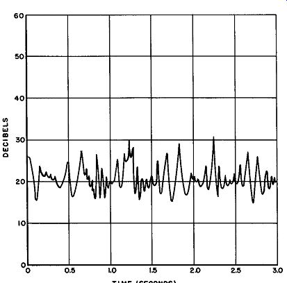
Fig. 19. Graph showing fast fading over a 180-mile scatter path at 400 mhz.
Figure 20 shows in somewhat exaggerated form the path geometry of a typical scatter circuit at a frequency in the range from 300 mhz to 5000 mhz. As explained previously, the mechanism of tropospheric scattering appears to be a function of heterogeneities in the dielectric constant of the air due to variations of moisture, temperature, and air density. Even though the attenuation of the signals may average about 70 db more than that of free space, the received signal field strengths are still substantially in excess of those which are predicted by earth diffraction effects alone.
The successful utilization of a path of this nature for communication over distances of 200 miles or more beyond the horizon calls for specialized equipment. High gain antennas, high-power transmitters, and space-diversity reception are now being employed in such communications circuits. Although the cost of such equipment normally exceeds that of standard transmitting gear by a considerable amount, its use is justified in most cases because it reduces the number of repeater stations required.
In discussing the path geometry of scatter transmission, the question of the effects of wave polarization frequently arises. Ac-curate data on this subject are not available at the present time.
Qualitative observations have demonstrated, however, that very little difference exists in transmission efficiency between vertically, horizontally, and circularly polarized waves. In addition, preliminary measurements indicate that the plane of polarization established at the transmitter is fully preserved over the scatter path and that the wave arrives at the receiver in virtually the same plane.
32. Antenna for VHF Scatter Circuits
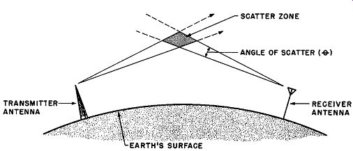
Fig. 20. Wave scattering.
Most of the antennas now in use are simple, center-fed circular paraboloid of revolution of various diameters. Large 60 foot-diameter arrays weighing about 6000 pounds are in common use; smaller antennas measuring about 28 feet in diameter are usually raised well above the ground to realize some additional gain, and are often equipped with adjustments for azimuth. Fabricated of welded aluminum tubing, these antennas are capable of withstanding winds up to 100 mph even when coated with ice.
The high cost of these arrays makes it almost mandatory that they be used for simultaneous transmission and reception - a system known as diplexing. Since there is a great difference in the amplitude levels of the received and transmitted signals -- sometimes in the order of 200 db -- diplexing is not easily accomplished.
The transmitted signal having the same frequency as the one to be received must be attenuated well below the minimum detectable signal and the transmitter itself must be carefully isolated from the receiver to prevent overloading.
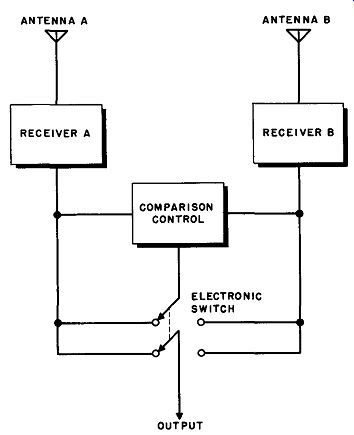
Fig. 21. Switching diversity.
33. Space Diversity Reception
The technique of diversity reception relies upon the fact that when a signal has faded to a low value on one antenna, it is quite probable that it will have increased in strength on another antenna situated some distance from the first.
Two methods have been used successfully for choosing the antenna that provides the best response automatically; one is called switching diversity and the other combination diversity.
Either of the systems may be applied to dual, triple, or quadruple antenna arrays.
Switching diversity utilizes as many receivers as there are antennas, a comparison control circuit, and an electronic switch, as shown in Fig. 21. In this dual antenna system, the signals are de modulated and amplified in individual receivers and then are fed to the comparison-control circuit. The latter compares the signal to-noise ratio of the received material, automatically throwing the electronic switch to the position that provides the best output.
Switching may be accomplished either before or after demodulation; the former is usually preferred because the transients produced by the switching devices are seldom as large in this case.
With switching diversity the poorer signal is completely rejected while the better is totally received. This does not always result in the best possible output since, as is often the case, a combination of the better aspects of the two signals would result in an improved signal-to-noise ratio. This is the idea behind combination diversity.
In combination diversity two or more receiver outputs may be connected in parallel. A control circuit is arranged to vary the output impedance of each receiver in such a manner that the impedance is roughly inversely proportional to the signal-to-noise ratio. Thus, as the signal-to-noise ratio improves as a result of fading effects, the impedance drops and the output of that particular receiver increases. If, at the same time, the second receiver displays a poor ratio, its impedance rises and its output falls oft.
The total output signal is, therefore, a combination of the best efforts of both receivers. If we add to this the fact that combination diversity reception does not suffer from switching transients, the growing popularity of this system becomes more understandable. (See Fig. 22.)
34. Ionospheric Scattering
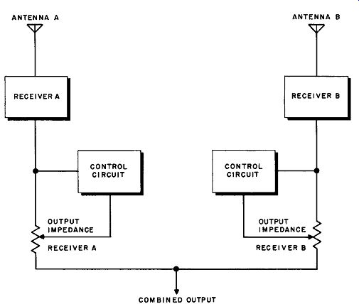
Fig. 22. Combination diversity.
All of the preceding material in this Section has dealt with tropospheric scattering of uhf and vhf radio signals. During 1950, discussions carried on among experimental scientists interested in scatter propagation in the troposphere caused certain speculations, which ultimately led to the discovery that scatter effects also occur in the ionosphere. Two distinct and separate fields of investigation have thus grown almost simultaneously, causing some confusion among readers. It is important to note carefully the differences in nature, range, and limitations of the two phenomena.
At low frequencies it is found that the intensity of ionospheric (sky wave) signals is not appreciably different from the free space values. As the frequency of the transmission rises above the maximum usable sky-wave frequency, the received signal begins to drop sharply. At one time it was assumed that if the frequency were raised sufficiently high, the signal would disappear altogether. It is now recognized that the drop-off curve is not discontinuous but has a "floor" below which there is no further drop-off. This floor is now known to be due to ionospheric scatter transmission.
It is believed that ionospheric scattering takes place from the lower E region. This phenomenon permits surprisingly reliable communication over distances ranging from 600 to 1200 miles by signals in the frequency spectrum from 25 mhz to 60 mhz.
Theories of ionospheric scattering. None of the theories of ionospheric scattering thus far proposed are adequate to explain all of the peculiarities of this method of propagation, although they have been of some assistance in many respects.
Turbulence theory. Many of the observed phenomena involving this type of scattering may be explained by predicating a homogeneous turbulence of the ionization gradient of the lower E region. Pressure fluctuations in a uniform gas, such as the atmosphere, accompanied by temperature variations at different altitudes, give rise to density fluctuations. This, in turn, results in electron density fluctuations called blob-s of turbulence, in which aerodynamic causes are responsible for the variations in ionization intensity. This theory seems to give the most complete explanation of observed phenomena.
Partial reflection theory. Some theorists hold to the belief that partial reflection from an ionospheric boundary region whose electrical density changes with height is enough to account for ionospheric scattering. Experimental workers in the field have found, however, that this theory can be successfully applied to observed results only if certain additional assumptions are made.
These assumptions involve changing irregularities in the ionization gradient, conditions which partially invalidate the "smooth" boundary reflection idea.
Meteor trail theory. It is believed by some that meteors moving through clouds of cosmic dust in the lower E region can produce non-homogeneous ionization, which partially or wholly ac counts for ionospheric scattering.
The signals received by this type of scattering are exceedingly complex; their nature may often be largely attributed to scattering from meteor trails. Yet their very complexity indicates that a single cause is improbable and that much experimental work remains to be done. Such work is expected to lead to a satisfactory integration of all of the worthwhile theories to provide an adequate explanation of all the observed phenomena.
35. QUIZ
(1) What is meant by fading?
(2) What explanations have been advanced for: long term fading? Short term fading?
(3) Describe and explain the essential elements of scatter transmission
(4) Illustrate, by diagram, the path geometry of a typical scatter circuit at a frequency in the range from 300 mhz to 5000 mhz.
(5) What is meant by "diplexing"?
(6) Draw a diagram that illustrates switching diversity.
(7) Explain the function of the comparison control in the diagram required for question 6.
(8) Describe and illustrate a combination diversity system.
(9) Give the essentials of the "turbulence" theory.
(10) Explain briefly the partial reflection theory; the meteor trail theory.