To Adjust the Ringing Coil in a Synchro-guide Horizontal Oscillator Circuit
Equipment: Low-capacitance probe.
Connections Required: Connect probe between input of ringing coil and ground, as shown in the following diagram. Feed probe output to vertical-input terminals of scope.
Procedure: Adjust scope controls for pattern as shown in following photos. Receiver must be tuned to a TV broadcast station or energized from a pattern generator having horizontal sync output.
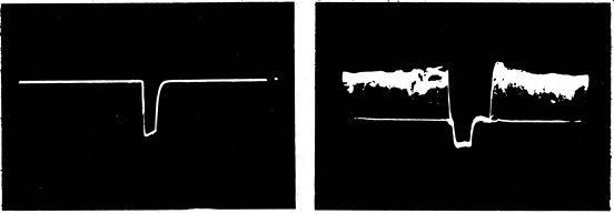
Evaluation of Results: Slug is adjusted in the ringing coil to bring the positive peaks of the pulse and sine wave to the same level.
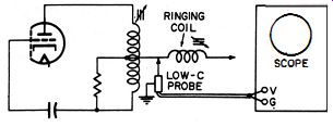
-- Test setup.
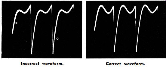
---- Incorrect waveform. Correct waveform.
++++++
U44
To Display Waveforms and Measure Peak-to-Peak Voltages In a Synchrolock Discriminator Circuit
Equipment: Low-capacitance probe.
Connections Required: Apply probe from plate 1 to ground and then from plate 2 to ground, as shown in the following illustration. Feed probe output to vertical-input terminals of scope.
Procedure: Adjust scope controls for typical pattern display as shown. Receiver must be tuned to TV station signal or driven by pattern generator having horizontal sync-pulse output.
Evaluation of Results : The normal waveform is a combined sine wave and sync pulse, as shown in the following waveform.
(The sync pulse will normally show high-frequency attenuation.) Wave shapes and peak-to-peak voltages should be compared with data in receiver service literature.
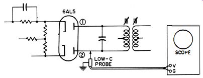
----- Test setup.
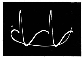
------ Synchrolock discriminator waveform.
++++++++
U45
To Check the Action of a Sync Separator
Equipment: Low-capacitance probe.
Connections Required: Apply probe at output of sync-separator tube. Feed probe output to vertical-input terminals of scope.
Procedure: Adjust scope controls for typical waveform as shown.
Receiver must be tuned to TV station signal or energized from pattern generator having sync-pulse output.
Evaluation of Results: Compare waveform (and peak-to-peak voltage) with data in receiver service literature. Good separation leaves all the camera signal behind. Poor separation is shown by passage of the camera signal. (See the following illustrations.)
-------- Good horizontal sync separation. Poor horizontal sync separation.
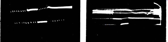
------ Good vertical sync separation. Poor vertical sync separation.
NOTE 64
Appearance of Pattern When 60-Cycle Hum Is Present
When sync separation is poor and substantial 60-cycle hum is present, no waveform will be seen. Instead, a picture appears on the scope screen, similar to a distorted image on a picture-tube screen. The reason for this display is similar to the one discussed in Note 30. (See the following photo.)
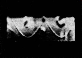
---- Beam displacement display, seen at output of faulty sync
separator, with strong 60-cycle hum voltage in signal.
++++++
U46
To Check Waveforms and Peak-to-Peak Voltages Through the Vertical Sync Integrator
Equipment: Low-capacitance probe.
Connections Required: Apply probe at terminal points in the vertical-sync integrator network. Feed probe output to vertical-input terminals of scope.
Procedure: Adjust scope controls for typical pattern as shown.
Receiver must be tuned to TV station signal or driven by pattern generator having sync-pulse output.
Evaluation of Results: Compare waveshapes and peak-to-peak voltages with data in receiver service literature. The merit of an integrator circuit is seen in its rejection of the horizontal sync pulses and development of the vertical sync pulse into a spike.
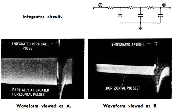
---- Integrator circuit.
--- Waveform viewed at A. Waveform viewed at B.
NOTE 65
Need for Correct Setting of Receiver Controls
Integrator waveforms (like many other receiver waveforms) will appear distorted unless the receiver controls are correctly set and correct test conditions used. Hence, check the receiver service data.
Quite often, it will state that the vertical oscillator be stopped and that vertical controls be set to specified positions.
NOTE 66
Apparent Failure of Integrator Network Due to Faults Outside of the Network
Apparent failure of the integrator network to eliminate horizontal pulses is sometimes caused by faults outside the network. For example, stray fields from the horizontal-sweep system may be reaching the integrator leads. To correct, dress the radiating leads away from the vertical-sync circuits, or investigate shielding conditions. In other cases, poor decoupling permits horizontal sweep or sync pulses to enter the vertical-oscillator circuit and mix with the integrator output waveform.
NOTE 67
Unstable Vertical-Integrator Output
Once in a while you will find an unstable vertical-integrator output.
The picture remains in vertical sync for a short time, then starts to roll upward. When the picture rolls upward, the vertical oscillator is breaking sync lock. A scope check will show that the pulse output from the integrator varies in peak-to-peak voltage. When the voltage falls to a low value, the picture rolls. This variation can be caused by poor decoupling, which permits interfering voltages to enter the vertical oscillator circuit. It can also be caused by faults anywhere in the signal or sync circuits which cause vertical sync punching. Poorly aligned IF amplifiers which are regenerative can cause this trouble. Gassy tubes in the high-frequency signal circuits can also be responsible. The scope is very useful ·in such cases for tracing the vertical sync waveform back through the circuits step-by-step to localize the defective circuit or component.
+++++++
U47
To Observe the Waveform and Measure Its Peak-to-Peak Voltage at the Grid of the Horizontal AFC Tube
Equipment: 100-to-1 capacitance-divider probe or 10-to-1 low capacitance probe.
Connections Required: Apply probe between grid of AFC tube and chassis ground. Feed probe output to vertical-input terminals of scope. 100-to-1 probe is preferred because of its lesser loading on the grid circuit.
Procedure: Adjust scope controls for the following pattern.
Evaluation of Results: Check waveshape and peak-to-peak voltage against specified data in receiver service literature
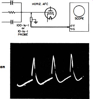
---- Test setup.
----- Typical waveform at the grid of an AFC tube.
+++