To Observe the Waveform and Measure the Peak-to-Peak Voltage at the Horizontal-Oscillator Grid
Equipment: 100-to-1 capacitance-divider probe or 10-to-1 low capacitance probe.
Connections Required: Apply probe between grid of horizontal oscillator tube and ground. (100-to-1 probe is preferred because its lower input capacitance detunes circuit less than 10-to-1 probe.)
Feed probe output to vertical-input terminals of scope.
Procedure: Adjust scope controls for display shown in the following.
Evaluation of Results: Peak-to-peak voltage should be within 20% of value specified in receiver service literature. Waveform should be reasonably close to specified waveshape.
HORiZ.OSC.
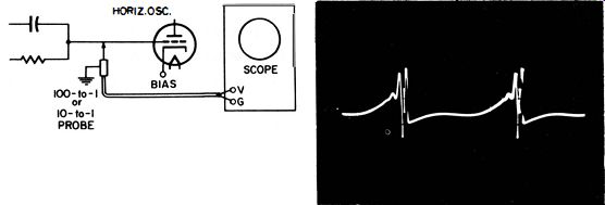
------ Test setup. ---------- Typical waveform observed in test.
(See receiver service literature for circuit under test)
++++++
U49
To Observe the Waveform and Measure Its Peak-to-Peak Voltage at the Grid of a Horizontal-Discharge Tube
Equipment: Low-capacitance probe.
Connections Required: Apply probe between grid of horizontal discharge tube and chassis ground. Feed probe output to vertical-input terminals of scope.
Procedure: Adjust scope controls for typical pattern, as shown.
Evaluation of Results: Compare waveshape and peak-to-peak voltage with data in receiver service literature.
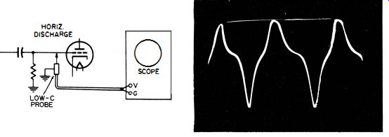
Test setup. ------ Typical waveform at grid of horizontal-discharge
tube.
++++++++++
U50
To Check the Waveform and Measure the Peak-to-Peak Voltage at the Grid of the Horizontal-Output Tube
Equipment : 10-to-1 high-impedance (compensated) probe.
Connections Required: Apply probe between grid and ground of the horizontal-output tube.
Connect probe cable to vertical-input terminals of scope.
Procedure: Adjust scope controls for typical pattern as shown.
Evaluation of Results: Observe waveform and compare with specified waveshape in receiver service data. Measure peak-to-peak voltage and compare with specified value. The observed peak-to-peak voltage will vary with the setting of the horizontal-drive control. Note that the test can be made with a direct cable to the scope in some instances. In others, a 10-to-1 probe is essential to avoid waveform distortion and voltage attenuation due to circuit loading.
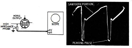
--- Test setup. Waveform at grid of horizontal-output tube.
++++++++
U51
-- To Check the Waveform and Peak-to-Peak Voltage at the Plate of the Horizontal-Output Tube
Equipment: 100-to-1 high-voltage, capacitance-divider probe.
Connections Required: Apply probe between the plate terminals of the horizontal-output tube and ground. Connect probe cable to vertical-input terminals of scope.
Procedure: Adjust scope controls for typical pattern as shown.
Evaluation of Results: Observe waveshape and measure its peak-to-peak voltage. Compare with data in receiver service notes.
Note that the setting of the drive adjustment will vary the peak-to-peak voltage.
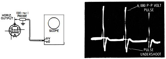
---- Test setup. ----- Waveform at plate of horizontal-output tube.
NOTE 68
Voltage Rating of 100-to-1
Probe A 100-to-1 capacitance-divider probe is generally rated for operation at voltages up to 10,000 peak-to-peak volts. Hence, it is adequate for testing at the plate of the horizontal-output tube. On the other hand, a 10-to-1 high-impedance compensated probe is usually rated to 600 peak-to-peak volts only. Therefore, a 10-to-1 probe must not be used in this test.
NOTE 69
Checking and Adjusting a 100-to-1
High-Voltage, Capacitance-Divider Probe for Attenuation Factor Measure the peak-to-peak voltage of the waveform at a moderately high signal voltage point in the horizontal sweep system, such as at the control grid of the horizontal-output tube, with the probe. Repeat the measurement with a direct cable to the vertical-input terminals of the scope. Observe the voltage value in the first test and compare with value obtained in the second test. Adjust trimmer capacitor of probe, if necessary, to obtain exactly 100-to-1 attenuation when the probe is used.
Note that if the scope has a decade attenuator (10-to-1 steps), the same deflections should be obtained when the direct connection is used and the attenuator moved up two steps, as when the test is made with the divider probe.
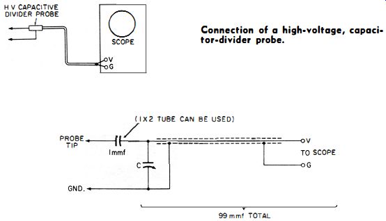
----- Connection of a high-voltage, capacitor-divider probe.
----- Configuration of a typical high-voltage, capacitor-divider probe.
++++++++
U52
To Check the Waveform and Peak-to-Peak Voltage at the Output of the Linearity-Coil Circuit
Equipment: 10-to-1 low-capacitance probe.
Connections Required: Apply probe between output terminal of linearity coil and chassis ground. Feed probe output to vertical-input terminals of scope.
Procedure: Adjust scope controls for typical pattern as follows.
Evaluation of Results: Compare waveshape and peak-to-peak voltage with data specified in receiver service literature, or compare with pattern obtained from another chassis of the same type.
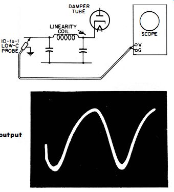
-------- Test setup.
--------- Typical waveform observed at output of linearity circuit.
++++++++++++
U53
To Check the Waveform and Peak-to-Peak Voltage at the Plate of the Damper Tube
Equipment: 100-to-1 capacitance-divider probe.
Connections Required: Apply probe between plate of damper tube and chassis ground. Feed probe output to vertical-input terminals of scope.
Procedure: Adjust scope controls for pattern as illustrated.
Evaluation of Results: Waveshape and peak-to-peak voltage should be compared with receiver service data or with pattern obtained from another receiver of the same type.
NOTE: It is good practice to use a 100-to-1 probe in this test, since the peak-to-peak voltage at the damper plate is high in some receivers.
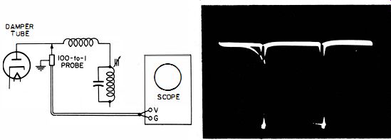
----------- Test setup. Typical waveform observed at damper tube plate.
+++++++++++
U54
To Check the Waveform and Peak-to-Peak Voltage of the High-Voltage Ripple
Equipment: 100-to-1 high-voltage, capacitance-divider probe and high-voltage filter capacitor.
Connections Required: Connect the high-voltage filter capacitor (may be any convenient value, such as 250 and 500 mmf) in series with probe. Connect at second-anode terminal of picture tube, as shown. Feed probe output to vertical-input terminals of scope.
Procedure: Adjust scope controls for pattern shown in the following.
Evaluation of Results : Peak-to-peak voltage is a measure of the effectiveness of the high-voltage filter. Insufficient filtering can cause variation in shading across the screen. Compare observed voltage with value found in known good receiver using the same size picture tube.
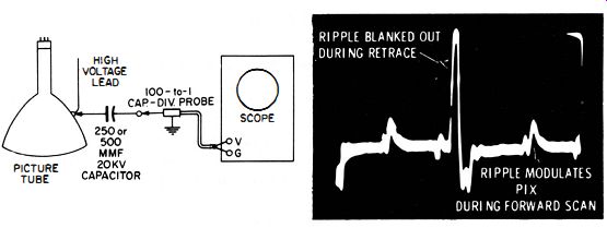
------- Test setup.
Typical ripple waveform in a high voltage, power-supply circuit.
+++++++++
U55
To Obtain the Waveform and Measure Its Peak-to- Peak Voltage Across the Horizontal-Deflection Coils
Equipment: 100-to-1 high-voltage, capacitor-divider probe.
Connections Required: Apply probe between "high" side of deflection coils and ground. Connect probe cable to vertical input terminals of scope.
Procedure: Adjust scope controls for typical pattern as shown.
Evaluation of Results: Compare waveform and peak-to-peak voltage value with data in receiver service literature. The peak-to-peak voltage varies with the setting of the horizontal-drive control.
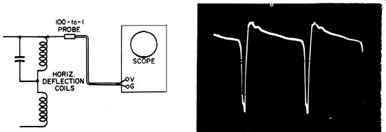
------- Test setup.
------ Waveform across horizontal-deflection coils.
NOTE 70
Interference in Sweep Circuit Waveforms
Typical interference in a sweep circuit waveform is observed in the foregoing illustration. Such interference is usually caused by stray fields reaching the vertical-input terminals of the scope. In such cases, the interference can be eliminated by using a scope having a shielded vertical-input connector instead of exposed binding posts.
NOTE 71
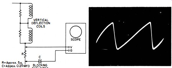
Connecting Scope Ground to Low Side of Deflection Coils
In most instances, the 100-to-1 probe can be grounded to chassis, and the observed waveform will be practically the same as the actual waveform across the horizontal-deflection coils. In some instances, however, there is sufficient impedance between the return lead of the coil and chassis ground for substantial distortion to occur. The true waveform can be obtained by connecting the ground lead of the probe to the "low" side of the coils via a blocking capacitor, as shown in the following illustration. Do not use a direct connection between the probe and the coil return lead, because this may make the scope case "hot" and can give the operator a B+ "bite."
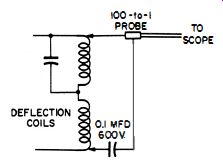
--- Method of connecting scope ground lead to the return lead of
the deflection coils.
NOTE 72
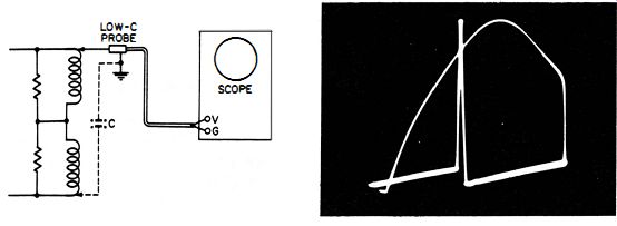
Need for Using Correct Probe When Viewing Waveform Across Deflection Coils
A 10-to-1 high-impedance compensated probe should not be used to check the waveform across the horizontal-deflection coils. Its input voltage rating is inadequate, and the probe may be damaged. For the same reason, a direct cable to the scope should not be used. Even if the scope input circuit will withstand the peak-to-peak voltage applied, many scopes overload badly under this condition. Severe waveform distortion results, as shown in the following photos.
--- Waveform observed across horizontal deflection coil, with
a 100-to-1 capacitance-divider probe.
Distortion of the waveform which occurs when the scope is used with a direct probe.
+++++++
U56
To Display the Sweep Current Waveform
Equipment: 5-ohm resistor.
Connections Required: Insert the resistor in series with the return lead from the horizontal-deflection coils. Connect a direct cable across the resistor. Feed cable output to vertical-input terminals of scope.
Procedure: Adjust scope controls for typical waveform, as shown in the following illustration.
Evaluation of Results: Waveform should have a linear sawtooth shape and be reasonably free from ringing or other transient distortion. Peak-to-peak current of waveform can be measured, if desired, with a scope calibrated in peak-to-peak volts per inch. With a 5-ohm resistor, a peak-to-peak current flow of 0.5 ampere will drop 2.5 peak-to-peak volts across the resistor. Because of the B+ voltage in the horizontal-deflection coils, the scope case becomes "hot" when the foregoing tests are being made unless the blocking capacitor C is added in series with the ground lead of the scope.
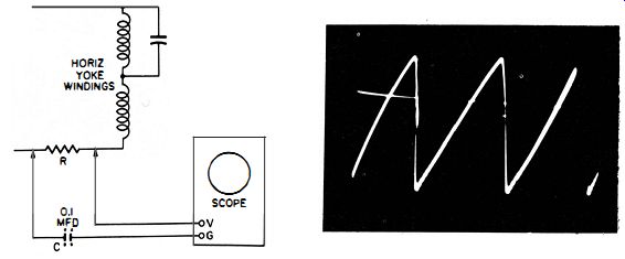
------ Test setup. Horizontal sweep current waveform.
NOTE 73
Value of Blocking Capacitor
When blocking capacitors are used in series with the ground lead of the scope, the capacitor must have a sufficiently high value to avoid 60 cycle hum interference in the pattern. The value should be at least 0.1 mfd; however, a higher value may be required in some tests.
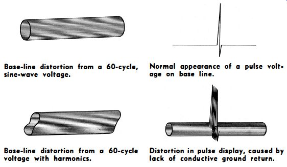
------- Base-line distortion from a 60-cycle, sine-wave voltage.
Base-line distortion from a 60-cycle voltage with harmonics.
Normal appearance of a pulse voltage on base line.
Distortion in pulse display, caused by lack of conductive ground return.
NOTE 74
Reason for Difference in Voltage and Current Waveforms
The horizontal sweep system has reactive circuits and operates upon the basis of tuned retrace. Hence, voltage and current waveforms in a circuit will always have different shapes. The same waveshape for voltage and current is found in purely resistive circuits only.
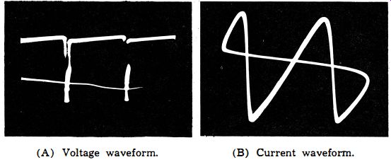
------ (A) Voltage waveform. (B) Current waveform.
Comparison of voltage and current waveforms in a typical sweep circuit.
++++++++
U57
To Check the Waveform and Peak-to-Peak Voltage at the Grid of the Vertical -Oscillator Tube
Equipment: 10-to-1 (or special) high-impedance compensated probe.
Connections Required: Apply probe between grid of vertical oscillator tube and chassis ground. Connect probe cable to vertical-input terminals of scope.
Procedure: Adjust scope controls for typical pattern, as illustrated in the following.
Evaluation of Results: Compare waveform and peak-to-peak voltage value with data in receiver service literature. In some receivers the pulse portion of the waveform is narrow and dim; reducing the vertical gain and advancing the intensity controls of the scope helps to improve its visibility.
---- Test setup. Waveform at grid of typical vertical oscillator
tube.
NOTE 7S Type of Probes Used in Vertical Circuits
A 100-to-1 capacitor-divider probe must not be used in vertical-circuit tests. The 60-cycle waveforms have too low a fundamental frequency to operate a capacitor-divider probe properly. The vertical-frequency waveforms will be distorted badly.
Use only compensated types of probes in vertical-circuit tests.
NOTE 76
100-to-1 High-Impedance Compensated Probe
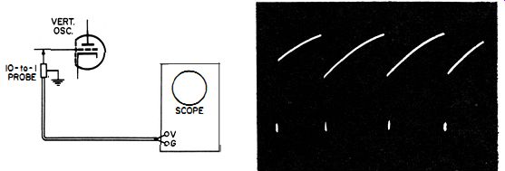
The vertical oscillator grid in many receivers is a very high-impedance circuit. Waveform distortion often occurs because of loading by a 10-to-1 probe. In such cases, use a 100-to-1 high-impedance compensated probe, as shown in the following illustration. This type of 100-to-1 probe is not available at the time of writing and must be constructed by the technician.
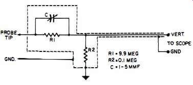
------ Configuration for a 100-to-1 high-impedance compensated probe.
(Adjust C for 100-to- 1 attenuation at 60 cycles and 100-khz)
NOTE 77
Cathode-Follower Type Probes
A few scope manufacturers have cathode-follower probes available for high-impedance circuit tests. These probes are better suited for tests at the grid of a vertical blocking oscillator than 10-to-1 Re high impedance probes.
+++++++
U58
To Display the Voltage Waveform Across the Vertical
Deflection Coils Equipment: 10-to-1 compensated probe.
Connections Required: Apply probe across vertical-deflection coils. Use a large series-blocking capacitor if "low" side is above ground. In many instances, probe can be returned to chassis ground, with little waveform distortion.
Procedure: Adjust scope controls for typical waveform, as shown in the following illustrations.
Evaluation of Results: Compare waveform and peak-to-peak voltage with data in receiver service literature.
-------- Test setup.
A typical voltage waveform across the vertical-deflection coils.
+++++++++++++++++++
U59
To Display the Current Waveform Through the Vertical
Deflection Coils
Equipment: 5-ohm resistor.
Connections Required: Insert resistor in return lead from the vertical-deflection coils. Connect direct cable across resistor.
Feed cable output to vertical-input terminals of scope.
Procedure: Adjust scope controls for typical pattern display, as shown in the following.
Evaluation of Results: A linear sawtooth display, without spurious transients or ringing components, should be observed.
Peak-to-peak current can be measured with a calibrated scope, by applying Ohm's law to relate current and voltage in the resistor.
--------- Test setup.
Current waveform of a typical vertical-deflection voltage.
NOTE 78
Observing Cross Talk in Vertical-Deflection Coils
A defective yoke or other faults in the yoke circuit will sometimes cause a thickening of the sloping portion in the current sawtooth. This thickening is caused by cross talk with the horizontal-deflection coils. In such cases, the details of the cross talk can be observed by changing the horizontal-sweep rate to 15,750 cycles and applying external sync from the horizontal circuit to the Ext. Mod.
post of the scope. When the vertical gain control and horizontal-gain control are advanced, we see a raster type display on the scope screen, with successive damped sine-wave patterns, as shown. Each horizontal circuit pulse shock-excites the circuits and cross talks into the vertical-deflection coils. There are 262.5 shock-excited waveforms in each vertical-scan interval.
------125 Display at 60-cycle horizontal sweep in scope. Display
at 15,750-cycle horizontal sweep in scope.
+++