AMAZON multi-meters discounts AMAZON oscilloscope discounts
It is now time to roll up our sleeves and take a good look at some all-transistor radios. Two important steps are behind us-knowing how transistors work, and being familiar with the function of the various components used with them.
This knowledge will now be applied by studying actual radios, since it is good operating procedure to know the type of circuit before tackling it. This is no different from the driver of an automobile who wants to see a road map before starting out on a trip to an unfamiliar place. Several aids will help the electronics technician map the best course:
1. Information printed on the radio, including model and serial numbers, and any special instructions or parts lay out charts.
2. Service manuals and schematics.
3. Previous experience with the same model.
A quick review of the schematic is usually helpful, even though similar models may have been encountered in the past.
This allows you to collect your thoughts before diving blindly ahead, and will usually save time in the long run. After be coming familiar with transistor schematics, it will take you only a few seconds to size up a radio by glancing at the schematic. These few seconds can save you many valuable minutes later.
After checking the batteries and glancing at the schematic to familiarize yourself with it, you will be ready to isolate the trouble to a stage. The mechanics of doing this--of pinning the trouble down to one stage or section-will be the major topic of this section. The section will begin, however, with some practice in schematic familiarization, since it plays such an important role in helping you isolate troubles efficiently.
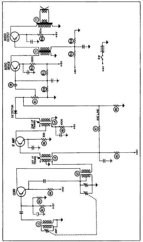
Fig. 3-1. Schematic of a typical AM transistor radio.
SCHEMATIC FAMILIARIZATION
The experienced technician can glance at a schematic and, in a few seconds, plan his whole trouble shooting approach.
To demonstrate this, let us examine the schematic in Fig. 3-1, in an effort to learn the greatest number of facts about the radio in the shortest possible time.
Two steps always precede a study of the schematic--listening to the radio and checking the battery voltage. From the schematic in Fig. 3-1, we learn there are four transistor stages--a converter, an IF, and two audio. Three of the transistor emitter arrows point toward the base and one points away from it, indicating there are three PNP transistors and one NPN transistor, the latter in the IF stage.
From the very beginning, we mentally divide the radio into five stages, each with a distinct job to do. These jobs are: Converter Changes the incoming signal from RF to IF Amp Detector Audio Driver Audio Output IF. Amplifies, or builds up, the IF signal.
Removes the IF and brings out the audio (accomplished by a diode, M2). Amplifies the audio received from the detector.
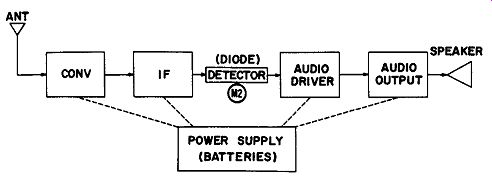
Fig. 3-2. Block diagram of the receiver in Fig. 3-1.
Builds up the audio still further until it can drive the speaker.
The power supply, which consists of batteries totaling 6 volts, could be considered a sixth stage. So the whole radio actually becomes a series of blocks, each one representing a stage as shown in Fig. 3-2. Our trouble will first be isolated to one of these stages and then pinpointed to a defective part or connection within that stage.
Most of the bypass and filter capacitors in Fig. 3-1 are shown in dotted lines to indicate they should be more or less overlooked when the schematic is first viewed. On the other hand, the parts which set up the DC idling conditions should be noted. This is the way the individual transistor circuits were progressively constructed before.
For example, a quick glance at Fig. 3-1 tells us all transistors have a resistor in their emitter leads for current stabilization.
The converter has R4, the IF stage has R6, the audio driver has R12, and R15 is in the emitter lead of the audio output.
Base bias is provided by a voltage divider across the battery supply. In addition, the IF amplifier provides some AGC voltage. The following voltage-divider resistors provide bias in each stage: Converter IF Amplifier Audio Driver
Audio Output
R2 and R3 RS, R7, and R9, plus a connection to volume control R1 R10 and R11 R13 and R14. Also in series with each base lead is a transformer winding to couple the signal into the input of each stage, (except the audio driver). The signal is coupled from the detector to the audio driver by means of a resistor-capacitor coupling network consisting of volume control R1 and coupling capacitor C9.
How about the collector lead of each transistor? We know the collector of an NPN transistor must go to the positive terminal of the battery, just as the plate of a vacuum tube is connected to a positive voltage. Conversely, the collector of a PNP transistor must go to the negative battery terminal. This checks out for the schematic in Fig. 3-1, where the collector lead of the NPN IF amplifier terminates at the +6-volt terminal, whereas the collector of all other stages returns to -6 volts via ground. (In this radio, the negative battery terminal is grounded. In others, however, the positive terminal may be grounded.) A transformer, in series with each collector lead, couples the signal into the following stage or to the speaker. The converter has two transformer windings in its collector lead, one being a feedback winding, L2, for the oscillator tank circuit, and the other a primary winding, L3, for the IF coil.
It is not important to note the value of the various parts at this time, but only to get an over-all picture of the circuit to assist you in mapping out the best troubleshooting approach.
For example, questions to be answered are: Does the radio have an RF amplifier stage between the antenna and the converter? ... This one does not.
Does the radio have one-or two-IF amplifier stages?
... This one has only one.
Does the radio use a diode detector? Or a transistor detector? ... This one uses a diode.
Does the radio have an audio driver stage? . . . This one does.
Does the radio have single-ended or push-pull output?
... This one has a single-ended output stage.
Are the circuits conventional in design? . . . Yes, they closely follow the basic amplifier and converter circuits discussed in Section 2.
Is the signal fed into the base of each transistor and sent out from the collector circuit? ... Yes, it is.
Does the radio use a negative or a positive ground? ... This one uses a negative ground.
Once these questions have been answered, it is time to isolate the trouble to a stage.
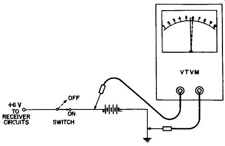
Fig. 3-3. Checking the battery voltage under load and no-load conditions.
CHECKING THE POWER SUPPLY
The power supply of the receiver in Fig. 3-1 consists of four penlight batteries which provide a total potential of 6 volts, plus some filter capacitors. This is the rating of four brand-new batteries under a no-load condition. With the radio turned on, the voltage should not drop below 5.4 volts, which represents a 10% decrease. This allows for a certain amount of aging, plus some voltage decrease due to current going through the batteries under the radio load. Fig. 3-3 shows the battery voltage readings with and without the receiver turned on. Incidentally, mercury batteries do not put out the same voltage as standard flashlight batteries. They usually run about 1.3 volts apiece. So four of them would measure about 5.2 volts. However, they hold their voltage much longer and steadier. For this reason, we become suspicious of more than a 5% decrease in their ratings. This means the voltage should not drop below 4.9 or 5.0 volts when mercury batteries are used.
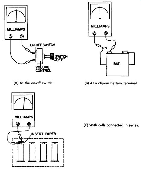
(A) At the on-off switch. (B) At a clip-on battery terminal. (C) With cells
connected in series. Fig. 3-4. Measuring the battery current.
Even if the batteries are normal, there could still be trouble in the power-supply system-especially if the radio is motor boating, squealing, rumbling, or whistling, or if the current drain through the batteries is above normal. The noises could indicate an open electrolytic filter capacitor on the battery line, and the high current drain, probably a shorted one. The best check for an open electrolytic is to shunt a new one across it and listen for improved performance.
Fig. 3-4 shows three ways of checking the battery current. One is to place a milliammeter across the On-Off switch (Fig. 3-4A) while the switch is off. However, this is not always easy to do because its terminals may not be readily accessible. If the battery is a one-piece unit instead of penlight cells, it will usually have clips which snap on to the top. Simply remove one of them and insert a milliammeter between the detached clip and its terminal (Fig. 3-4B). Then turn the radio on and note the current drain. If the batteries are penlight cells mounted in clips, simply insert a piece of paper between one end of any cell and its clip. Then turn the radio on and measure the current from the insulated battery terminal to its clip (Fig. 3-4C). The milliammeter should always be inserted in series with the batteries so it measures the current the radio draws from them. A drain of several times normal indicates a short on the battery line or in the electrolytic capacitor. Normal values are usually given in the service information. If not, an estimate can be made. Some of the larger table-model portables may draw up to 15-25 milliamperes. Most portables, however, are in the 4-15 milliampere range. Readings are always taken with no signal entering the radio and the volume control at minimum, because loud audio will increase the drain. This point should also be realized so you can answer the customer who asks, "Why do Mrs. Smith's batteries last longer than mine?" If the current drain is not excessive, your customer may be playing the radio too loudly. This is more noticeable in radios with push-pull output, since the output transistors are biased primarily by the input signal-the louder the input signal, the larger the bias voltage.
Current drain, unless quite excessive, should not be a source of concern. There are cases where several variables, including the idling currents of the various transistors, may make a 25 percent increase or decrease from the normal rated current not excessive at all. Separate power supplies, called battery eliminators, are quite handy for testing portable radios. They usually contain a milliammeter as well as a voltmeter so that current is constantly monitored.
STAGE ISOLATION METHODS
Assuming the battery voltage and current are fairly normal and there are no undesirable noises in the radio, the batteries and battery-line electrolytics can be considered in good shape.
The next step is to find out what stage or section of the radio is not operating properly.
The methods most commonly used to localize trouble in a radio circuit are signal injection, signal tracing, and personal observation. The simplest and most convenient method--personally observing and listening to the radio-is probably the most neglected of all. The proper use of test equipment to inject or trace signals in a radio is extremely valuable to know, but should never be used until the radio has been given expert personal observation. Then if the trouble is not localized, test equipment is brought into action without delay. The test equipment (such as signal generators and signal tracers) is used on transistor radios in much the same manner as on vacuum-tube radios. However, there are some tricks which will not only save a lot of time, but also prevent serious errors in localizing the trouble spots.
Isolation by Personal Observation
Most of us have two very valuable pieces of "test equipment" that are always with us and cost us nothing. These are our eyes and ears--a most precious gift which, properly used, can become your best detective and greatest timesaver.
Can you imagine how difficult it would be to try to de scribe, by words alone, what the inside of a radio looks like to someone who had never seen one? One glance, according to a Chinese proverb, would be worth 10,000 words to that individual. Or think how hard it would be to explain what music sounds like to a deaf person. Ten seconds of sound would be worth 10 million words. Yet we are sometimes prone to dive into a radio without giving it those few precious seconds of personal observation.
Listening Checks
What might the technician in Fig. 3-5 learn by holding the portable to his ear? First of all, he will find out what the radio really sounds like, instead of relying solely on the customer's word description of it. This does not mean the customer's description should not be obtained, because the radio may not act the same at all times. But word descriptions should always be followed by a careful listening test, which may bring out defects the customer was not even aware of. An example of this would be when a customer complains his radio is weak, but had not noticed that it is also distorted, or perhaps that the volume control is scratchy when moved.
Customer approval for the repair of all these defects would be desirable, because it will mean better customer satisfaction and more profit for you.
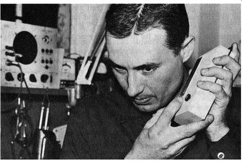
Fig. 3-5. Listening to the receiver call often give a clue to the trouble.
Some transistor radios have a "thump" ( or "pop") loud enough to be heard when the speaker is held to the ear and the radio turned on and off. The "thump" indicates the speaker and output stage are working. (This is not true in all portables, however.) It occurs because transistors require no warm-up time, but are ready to start conducting the instant voltage is applied. Enough current is sent through the speaker to cause a slight noise when the switch is turned off or on (although it may not be heard with some circuit designs or in noisy rooms). What else can be learned by listening to the radio? In many transistor radios, a small "hiss" is produced by the transistors in the front-end of the radio (RF or converter stage). If there are IF and audio-amplifier stages, this "hiss" may be heard in the speaker when the volume control is turned all the way up. Since the "hiss" requires considerable amplification before it can be heard in the speaker, the presence of a normal amount usually means all amplifiers are working. If so, the trouble may be due to a defective oscillator or antenna-items which would not affect the normal hiss level. An extra loud hiss, however, may be due to a defective transistor.
Jarring or shaking the radio while listening to it will often show up intermittents. The best practice is to carefully remove the covers and try to keep the radio inoperative long enough to locate the trouble. If the radio starts playing again before the covers are removed, tapping at various points will probably make it cut out again later.
If the radio operates in one position but suddenly quits when it is gently turned over, an iron sleeve or core in one of the IF transformers may be loose and has changed position.
Are there whistles on each station? If so, possibly a filter capacitor is not doing its job properly or the battery voltage is low.
Visual Checks
Now for some of the things that can be learned by a good visual check of the radio. As the technician carefully looks over the set, here are some of the questions he will be asking himself: Are all connections good? Are there any breaks in the printed circuits? Do any capacitors or batteries show signs of having leaked or corroded? Are any parts charred or burned? Is the radio case cracked or dirty? Is the dial calibration reasonably accurate; if not, possibly the oscillator alignment has been tampered with, or the dial indicator has slipped? Are there any loose solder chips, pieces of wire, or screws which could cause a short? Are there any metal chips lying on the speaker cone which could cause speaker buzz? Is the speaker cone torn or damaged? The sight and sound checks mentioned in this section would probably lead to the discovery of at least 25%, and possibly more, of all the troubles encountered. They require the easiest-to-use and most readily available test equipment--our eyes and ears. Their proper employment can help us not only locate troubles in a direct manner, but also form the strategy for the other tests to follow.
Isolation by Signal Injection
If personal observation for visible and audible symptoms does not uncover the defect, signal injection is one of the best means of isolating the trouble to a stage or small area of the radio. This applies when the radio is dead or weak and the battery checks outlined previously are perfectly normal.
Signal injection (also known as signal substitution) means to insert test signals at various points and compare the results with those which would be expected from a good radio of the same type. The test signals are amplified by the stages being tested in the radio, provided the stages are working properly.
They are then picked up at the speaker, where they can be heard and checked by ear, or even viewed on an output meter if desired.
From our definition of signal injection, we can see that there are several requirements for a good test. First, test signals must be available. Second, the proper points to insert them must be known; and third, the approximate result to be expected from a normal radio of that type should be known so deviations from normal can be easily recognized.
Signal generators which generate RF, IF, and audio test signals are found in every modern service shop or engineering laboratory. Except for tube or transistor testers and voltmeters, they are probably the most popular commercial test instrument. Fig. 3-6 shows a generator being used to send a signal into the audio stages of a transistor radio.
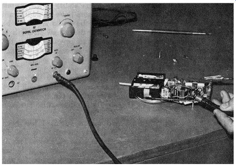
Fig. 3-6. Injecting a signal into the audio stages of a transistor radio.
There are other means of sending test signals into the radio.
These include noise generators and circuit-disturbance "click" tests, which will be covered in detail later. Although very convenient, these tests have certain limitations which must be realized when they are used.
Signal-Generator Test Points
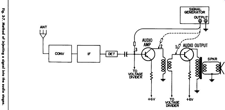
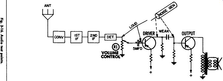
The user of the signal generator thinks in terms of blocks and simplified schematics. He sees the basic circuit of the stages being checked at the time, but only visualizes the blocks for the remaining ones. For example, in Fig. 3-7 the signal is first inserted at the input, or base, of the audio-output transistor (point 1). Most signal generators send out a 400-cycle audio note, which would be sent into the output transistor through the test probe. Normally, of course, audio from radio stations would be sent to this point by the audio driver stage.
But during our test, we are substituting the signal generator for the regular audio signal to determine if the audio-output stage is working. If the trouble is in another stage, the signal generator will be heard on the speaker-indicating the output stage is doing its job. However, if the trouble is in the audio output stage, the signal at point 1 will not be heard in the speaker, or else will be weaker than normal.
From this discussion, we see that there are two factors which will determine how loud the signal will sound when injected at point 1 in Fig. 3-7. They are the strength of the signal from the signal generator and the ability of the output stage to amplify it. Most signal generators have an audio gain control which allows the strength of the audio signal to be varied. (In some simpler generators, the signal strength is fixed.) Nevertheless, it is important to practice using the generator on various radios so you can become familiar with the results obtained when a stage is working properly.
Most portable radios use fairly conventional circuits. Thus, the output stage of one radio will be similar to the one in many others. This means the signal-generator output will have the greatest effect on the signal strength at the speaker--another reason for becoming thoroughly familiar with your own generator.
---------- Fig. 3-7
---------- Fig. 3-8.
Let's go back to Fig. 3-7 and assume point 1 has been checked. Going to injection point 2, note that there is a slight increase in signal when the probe is touched there. This is normal because the driver transformer is usually a better match for the signal generator on the primary side. So the result indicates the transformer is all right. When the probe is moved to point 3, a still greater signal should be heard, indicating the audio driver stage is working. At points 1 and 2 there was only one transistor between the test point and the speaker; so the signal would be fairly weak. At point 3 another transistor is in the signal path; so the amplification should be greater. When, after practice, it is learned what type of signal can usually be expected at point 3 for a given signal generator setting, this point will usually be the first one chosen.
Test points 1 and 2 can then be ignored, unless the audio signal applied at point 3 is very weak or is dead.
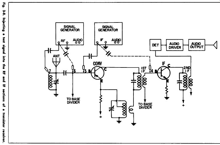
After the audio amplifiers are checked and found to be working properly, it must be assumed the trouble is in one of the other stages. The audio system is then thought of as several blocks which are good, and the troubleshooter visualizes the major parts of the remaining circuits, as shown in Fig. 3-8.
Test points 4 and 5 test the ability of the IF and converter stages to pass the IF signal, and test points 6 and 7, the ability of the radio to receive RF signals. A capacitor of about 0.1 mfd must be inserted in the test lead to protect the transistors; otherwise, they may be grounded through the signal generator.
This is called an "isolation" capacitor, which most signal generators already have in series with the audio output internally, but not with the RF-IF output. For this reason, one must be inserted for RF or IF checks. A glance inside the signal generator or at its schematic will prove this point.
If the IF signal from the generator is heard at point 4 but not at point 5, it can be assumed the converter stage or 1st IF transformer is defective. Again, it is important to become familiar with the normal output to be expected at each point.
Of course, all tests are meaningless unless the proper settings are used for the signal generator.
Setting the Signal-Generator Controls
Most signal generators have two major types of output-RF and audio. The audio output is usually fixed at 400 cycles, whereas the RF output is variable over a wide range, including the IF frequencies. This range is on a large frequency selector dial with several bands of frequencies marked on it. A few signal generators, built only for radio use, have some of the popular frequencies available in a step-type, rather than a continuously variable control.
An audio signal is desired when audio stages are being tested. It is obtained from the generator in Fig. 3-9 by:
1. Turning emission selector (D) to the "audio" position.
2. Turning the audio gain control (A) to the position which gives the desired signal strength.
3. Connecting the red and the black leads to the radio being tested-black to the radio chassis and red to the test point.
That's all there is to it. As the audio gain control is turned clockwise, more audio signal will be injected into the radio.
When selector (D) is in the "audio" position, the only control connected into the circuit is the audio gain control (A). Controls B and C have no bearing on the signal at the audio output jacks. The RF output jack is not used during audio checks, of course.
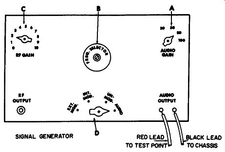
Fig. 3-9. Typical settings of the signal-generator control when the audio
section is being tested.
In checking the IF system in a radio, the published IF frequency should be selected on the signal generator. Popular IF frequencies are 262, 455, and 465 khz for broadcast-band receivers. The most widely used one is 455 khz. The proper IF frequency can be found in the radio service literature. A pure, unmodulated IF signal cannot be heard in the speaker. It must be modulated, which means some form of audio must be mixed with the IF signal.
To obtain a modulated IF signal from the signal generator shown previously, proceed as follows:
1. Turn emission selector (D) to the "internally modulate" position (see Fig. 3-10).
2. Turn the frequency selector dial to select the IF frequency of the radio being tested. (This also requires a band selection on a band-selector switch when more than one band is marked on the dial.)
3. Set the audio gain control (A) to a moderate setting. (If the control is marked in percent of modulation, use 30%. Otherwise, use about half the maximum audio gain.)
4. Set the RF gain control (C) to the position giving the desired signal strength. If it is not known, start at a low value.
5. Connect a coaxial shielded lead to the RF output jack.
Ground the shield to the radio chassis, and insert a 0.1 mfd capacitor in the main lead to serve as a test probe.
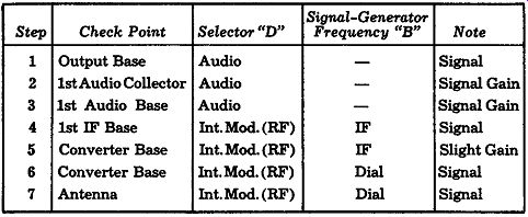
--------------- TABLE 3-1. Signal-injection test points.
------------------
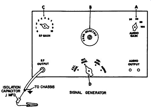
Fig. 3-10. Generator setup for checking the RF and IF sections of a receiver.
You are now ready to connect the test probe to a radio.
The reason for starting with a low RF gain setting is to pre vent overdriving and "blocking" of the transistors. Blocking makes the transistors sound as if they are not amplifying the signal, when they are actually just being overdriven. A reduced setting of the RF gain will unblock the transistors and allow the signal to come through better. Tubes are not subject to this condition nearly as much as transistors.
Table 3-1 is a summary of the signal-generator settings for each test point discussed so far.
Locating the Test Points
After the signal generator has been set to produce the desired type of signal, the proper point to inject it in the radio must be found.
Test points are easily located by using transistor leads, provided they are long enough and not crowded by other nearby parts. The base leads of IF transistors, for example, are usually easy to locate because they are near the IF transformers. Once the transistor is located, it is simple to find the desired lead where the generator is to be connected. As shown in Fig. 3-11, most small transistors use one of three lead spacings. Most germanium transistors use the triangle pattern, with base lead in the center. Some manufacturers use that same case for their silicon transistors, but others use a molded plastic case with one flat side and collector lead in the center. The service literature will usually specify the lead orientation, and also show where the various transistors are located.
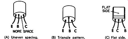
Fig. 3-11. Three methods of identifying transistor leads. (A) Uneven spacing.
(B) Triangle pattern. (C) Flat side.
In some very compact radios, it is almost impossible to reach a transistor lead from the top of the circuit board because other parts are mounted so close to the transistor. It is therefore advisable to troubleshoot the radio from the bottom of the circuit board. This is not really as difficult as it might sound, provided adequate service literature is available.
Fig. 3-12 shows a schematic of a transistor portable with two IF, a converter, and two audio-amplifier stages. Fig. 3-13 is a photograph of the bottom of the circuit board, showing the copper conductor rails. Note that certain conductors are numbered and pointed out by arrows. Those same numbers can also be found on the schematic (Fig. 3-12), showing the points where the various conductors are connected into the circuit.
Thus, it is very simple to find the transistor test points on the bottom of a circuit board.
Let us assume we want to inject a signal at the 1st IF transistor base element. The schematic tells us this is check point 9. This number is then found on the circuit board picture (Fig. 3-13). It is then easy to locate the same conductor on the circuit board, provided the radio and the circuit-board picture are facing in the same direction on the bench.
Isolation by Noise Tests
Large signal generators are not always required to track down troubles. Small noise generators also can be used, provided certain limitations are realized. In fact, some technicians prefer to use simple generators on almost all radios, reserving the larger ones for very tough troubles and for alignment.
One type of noise generator is shown in Fig. 3-14. It consists of a transistor oscillator which generates a signal sounding much like a doorbell buzzer. The fundamental output frequency is in the audio range, but the signal is rich in harmonics. This means that IF as well as RF signals are produced, allowing the buzzing noise to pass easily through the RF, converter, and IF tuned circuits. So this is actually an audio, IF, and RF generator combined into one, and no frequency selections are required because all signals are produced at the same time. The noise generator is built into a rectangular box and has a volume control to allow the output signal strength to be adjusted.
A pencil-type noise generator is shown in Fig. 3-15. It has no volume control, although its output can be increased some what by grounding the generator case to the radio being tested.
This unit and the one in Fig. 3-14 are battery-powered, the pencil unit containing a small battery at the top of the cylinder.
Because the noise it makes resembles the buzz of a mosquito, the popular pencil-type generator in Fig. 3-15 carries the trade name Mosquito.
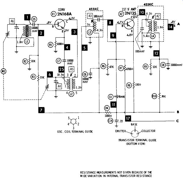
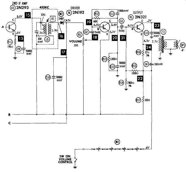
Fig. 3-12. Schematic of a typical five-transistor AM receiver.
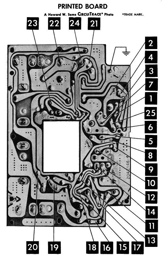
Fig. 3-13. Circuit board of receiver in Fig. 3-12, showing check points.
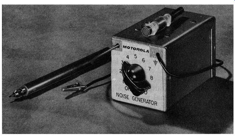
Fig. 3-14. A typical noise generator. (Courtesy of Motorola Communications
and Electronics, Inc.)
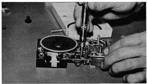
Fig. 3-15. The "Mosquito" noise generator In use.
Test Point for Noise Generators
The test points where noise signals can be injected are about the same as the ones for a signal generator. This means the noise can generally be injected at the base and collector elements, although there are some exceptions to this.
The first logical check would be to determine whether or not the audio stages are working. We are assuming, of course, that the battery voltage and current have been checked and are normal; also, that personal observation checks have been made to determine any obvious defects, such as loose wires, bad solder joints, cracks in the circuit board, etc.
In checking the audio system, one of two points should be used-the volume control or the base lead of the driver transistor. The choice here depends on which one is more accessible in the radio being checked. The high end of the volume control is a good place to start, or the center arm can be used if the control is turned to its maximum position.
If the volume control cannot be reached easily, the base (B) terminal of the driver transistor is a good place to start. If a fairly loud noise is heard when the noise generator is touched to one of those two points, we can assume the audio stages are performing. This one little check practically "cuts the radio in half," allowing us to free our mind of the audio stages and concentrate on the rest of the radio. This check, of course, is not very reliable for distorted radios, since the sound will still come through even if the audio stages were at fault. Distortion checks will be covered later.
If the noise signal does not get through the audio system, the generator can be moved to the collector of the driver, or to the base of the output stage. However, at these points the noise-generator signal will normally be much weaker when it reaches the speaker, because there will be only one transistor stage between the generator and speaker. Some small generators can barely be heard at these points. Nevertheless, a weak signal does indicate the output stage is working-which is what we want to know. The trouble can then be assumed to be in the driver stage, since we previously determined that the audio system was not functioning.
Most audio generators have a fairly high impedance output.
This means the noise from the speaker will probably be a little louder when the signal from the generator in Fig. 3-16 is applied to the collector of the driver than when applied to the base of the output stage. This is especially true in radios using transformer coupling between those two stages. however, neither test point is used unless the first test at the input of the driver stage fails to produce a good signal.
Do not expect to hear the signal if it is applied directly to the speaker or at the collector of the output stage, since there is no amplification at those points.
Now let us assume the audio system is working, as evidenced by the first check at the volume control or driver base. So we want to find out whether the trouble is in the IF system, or in the converter or antenna. The next main test point would be at the 1st IF base. If a good signal passes through when injected at that point, we can assume the IF system is working.
CAUTION:
Make sure to set the radio volume control at maximum for all tests.
If no signal is heard, check the IF system by taking voltage readings and making other tests, in accordance with suggestions in later sections of this guide. Many noise generators will not produce enough signal to be heard at some points.
For example, at the 2nd IF base, a pencil-type noise generator may not produce any signal at the speaker, even if the receiver is perfectly normal. Sometimes the same generator may produce a weak signal at the 2nd IF base, provided its case is grounded to the radio chassis.
This again points out the importance of knowing the capability of your own generator, to prevent your being mis led into suspecting trouble in the wrong stage of a radio.
If the IF stages are working, as evidenced by a fairly loud signal at the 1st IF base, check the converter stage.
Usually, very little gain can be noted in here. That is, the signal injected at the converter base will probably produce about the same noise in the speaker as one injected at the 1st IF base. However, if the noise is greatly decreased or is lost, the converter stage should be checked.
Assuming good noise was heard when injected at each of the major test points--audio driver, 1st IF, and converter base--then where would the trouble be? Usually in one of three places--the antenna, the oscillator, or one of the IF transformers. Detuned IF transformers can allow noise signals to pass through, since the noise is a random frequency spread over a broad spectrum. (This also includes the ones detuned because of an open capacitor inside the can.)
Noise-Generator Summary
Small noise generators are easy to use because they require no adjustments-or at most, only a simple output-gain adjustment.
The major test points are (1) the 1st audio base (or volume control), (2) the 1st IF base, and (3) the converter base. Loss of signal at any of these points indicates a defect in that section of the radio. If you desire to further isolate the trouble before taking voltage measurements, here are several pointers you must remember:
1. Some small generators do not put out enough signal to be heard when injected in the output stage or the 2nd IF base.
2. The output of some noise generators with no gain control can be increased slightly by grounding the generator case to the radio chassis.
3. Noise can sometimes be fed through detuned or defective IF transformers.
Provided these precautions are kept in mind, the noise generator offers somewhat of a short cut to the larger, all-purpose signal generators for trouble isolation. But it should not be used for receiver alignment.
Probably the biggest advantages of the noise generator are that it does not have to be tuned and it usually cannot put out enough signal to severely "block" a transistor stage.
Simplified Signal Injection
The noise test can be simplified still further, since there are several other ways to produce noise in a radio.
One of the simplest-long used in vacuum tube radios, but strictly taboo for transistor sets--is the screwdriver method of directly grounding various points while listening for a click or pop. This technique cannot be used on transistor radios because the transistor could be destroyed by being shocked be yond its maximum limits. However, this method, sometimes given the sophisticated title of "circuit disturbance" or "shock injection," is very satisfactory for vacuum-tube circuits since they are not nearly as sensitive to bias changes.
By modifying this method slightly, the author developed what has proven to be one of the most popular methods of isolating trouble in very weak or in dead transistor radios, especially portables. It is called simply the click test.
The Click Test
The click test consists of grounding certain test points through a resistor and listening for a click. The resistor in the test lead should have enough resistance to prevent the transistors from being damaged and still allow the click or pop to be heard. A 10,000- or 12,000-ohm, ½- or 1-watt resistor is usually satisfactory. Many different makes of transistor radios have been checked without any damage to components. But if any doubt exists about damaging a particular radio, consult the manufacturer's information before performing the test.
Your own body resistance is perfectly safe to use as the click-test resistor. Simply ground one hand to the chassis as shown in Fig. 3-17, and hold the metal shank of a screwdriver in the other. Then touch the screwdriver repeatedly at the various test points and listen for a slight click.
As with signal and noise generators, the base or collector elements of the transistors can be used for test points most of the time. Sometimes, however, clicks will not be produced even when the radio is working normally. This will be discussed later.
If a radio is not familiar or has never been tested in this manner before, or if the manufacturer has not been asked about the safety of this test, the collector leads are the safest ones to use. The reason is that a change in the collector voltage has very little effect on the conduction of a transistor, ...
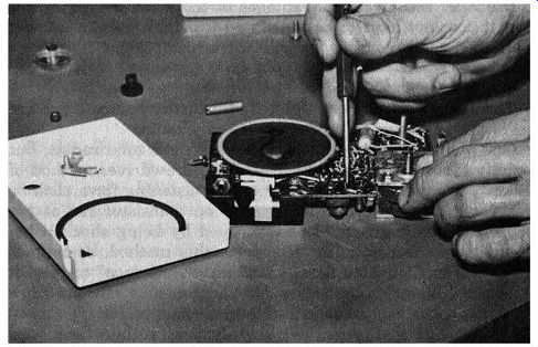
Fig. 3-17. Using the body resistance to protect the transistor when a "click
test" is made.
... whereas a change in the base voltage does. So a transistor with a very low current and power rating could conceivably be damaged as the "click resistor" is touched to one of the base leads. However, this has never happened in our tests.
The next step after checking the batteries is to make certain the audio amplifiers are working. Clip one side of the test resistor to the chassis, and touch the other end to the base of the 1st audio or driver transistor. Tap this point several times rapidly; if a click is heard, the audio stages are probably working. If nothing is heard, the audio stages should be checked. A click at the collector of the driver transistor probably indicates the output stage is working. But you should not expect to hear a click at the collector of the output stage because there is no amplification between that point and the speaker.
Next, how about the IF section of the radio? It can be easily checked by "clicking" the test resistor or test probe, which is grounded through your body resistance, on and off the converter collector lead. If clicks get through to the speaker from that point, you can assume the IF and audio stages are working. If nothing is heard, the IF stages should be checked.
If the IF stages are working, the next step is to check the converter stage. There are several ways to check a converter or oscillator stage. A click test could be made at the converter base, but a good click at that point does not tell us whether the oscillator portion of the converter is working. However, if the oscillator is oscillating, chances are the rest of the converter stage is also working.
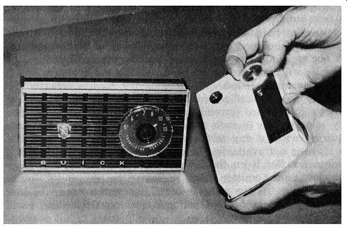
Fig. 3-18. A quick method of determining if the oscillator is operating.
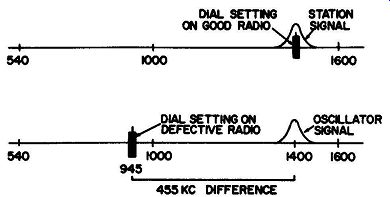
Fig. 3-19. Beat will occur at approximate position of dial pointers if the
suspected oscillator is operating.
Checking the oscillator in a transistor radio is one of the easiest checks to make, provided another radio is available.
The good radio is tuned to a fairly strong station in the upper, or high-frequency, half of the band. Then the radio being checked is held close to the good radio (Fig. 3-18) and slowly tuned across the band. When the oscillator in the defective radio passes the station on the good one, a whistle, or heterodyne, will be heard. It will usually occur when the dial of the defective radio is tuned approximately one IF frequency lower than the dial of the good radio ( not when they are both tuned to the same spot). This is shown in Fig. 3-19.
The reason is that the oscillator is usually generating a signal a few hundred kilocycles higher than its own frequency, so the oscillator signal from the defective radio will beat with the station on the good one and cause a whistle. If the oscillator is not working, the two cannot beat together. Therefore, no whistle will be heard in the good radio as the defective one is tuned across the band.
Most portable-radio oscillators will radiate their signal at least a foot or two (provided they are not completely shielded by metal). This is such a simple check that it can be made quickly without any test equipment except a spare radio. If a spare is not available, the oscillator can be checked with a voltmeter. Set it on the lowest DC voltage scale, and place one lead on the emitter of the oscillator transistor and the other on the base. As the radio is tuned across the band, the bias will vary slightly if the oscillator is working. Otherwise, it will stay constant.
A defective antenna circuit will not usually keep the converter from working. The antenna circuit can usually be given a quick check by "clicking" at the stator of the antenna vari able. A simple way to do this is to hold your hand on the metal shaft of a screwdriver, and gently touch its tip on and off the ungrounded terminal of the variable. A continuity check of the antenna itself would also be in order. Clicks near the antenna end of the radio should never be made, of course, until the audio, IF, and converter have been checked.
This brings out the importance of systematic troubleshooting. Never jump around from one end of the radio to the other.
Always check each section in order, starting at the audio section and working toward the antenna. This applies for any method of signal injection or substitution.
Table 3-2 lists the click test points on most transistor radios.
The major test points, for checking the audio, IF, and converter sections, are in bold letters. As the troubleshooter becomes more familiar with this method of trouble isolation, he may want to use some of the other check points to pinpoint the trouble before making stage voltage. checks. However, an attempt to tie it down too closely by signal injection can sometimes cause erroneous results. Here is an example: The radio is dead. Clicks at the input of the driver stage show the audio amplifiers are working. However, no click is heard at the collector of the converter stage, indicating the test signal is not being passed through the IF stages.
---------------- TABLE 3-2.
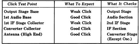
Points where click tests are made, and results to be expected.
Click Test Point What To Expect What It Checks
Output Stage Base Weak Click Output Stage 1st Audio Base Good Click Audio Section 1st IF Stage Collector Weak Click 2nd IF Stage Converter Collector Good Click IF Section Antenna (High End) Good Click Converter Stage (Except Osc.)
------------------
The collector of the 1st IF stage is then "clicked" by the 10,000-ohm resistor, but nothing is heard. The trouble shooter therefore logically assumes the trouble is in the 2nd IF stage, since it is not passing the click signal sent to it. So voltages are measured in the 2nd IF stage, but are perfectly normal. In fact, nothing wrong can be found in the 2nd IF stage. The question is, "What happened? ... What went wrong with the test?"
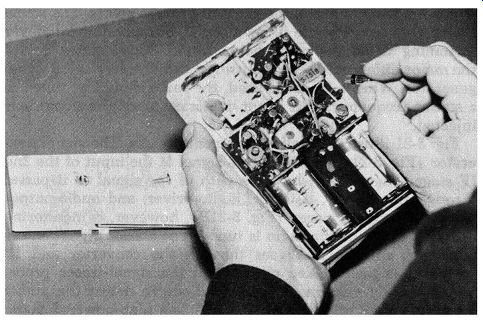
Fig. 3-20. Performing the click test by removing and replacing a transistor
in its socket.
The answer is stage interaction. The trouble was actually a partially shorted or a leaky 1st IF transistor which severely loaded down (and almost shorted out) the IF transformer between the 1st and 2nd IF stages. This, of course, prevented the test signal from entering the 2nd IF stage. So that stage appeared to be bad. In other words, it is not always profitable to try isolating the trouble too closely by signal injection. Isolation should be limited to a section-audio, IF, converter instead of to a single stage. If the troubleshooter does isolate the trouble to a specific stage by using all of the test points, he should still remember that the trouble may actually be in an adjacent stage.
Another rapid and convenient method of click testing, in radios using transistor sockets instead of directly soldering the leads into the circuit, is to pull the transistors and plug them back in again while listening for a click. This is shown in Fig. 3-20. In radios containing two IF stages, the following transistors will usually produce a click-the 1st audio (or driver), 1st IF, and converter. The audio-driver click checks the audio stages; the 1st IF transistor, the IF stages; and the converter transistor, the converter stage (for noise only). The oscillator should still be checked by one of the previous methods, such as listening on a nearby receiver or monitoring the bias while tuning across the band.
Isolation by Signal Tracer
We have been talking about injecting a signal with a generator, or by using the click test, and listening for it in the speaker.
The test signal is amplified by one or more transistor stages in the audio system before it reaches the speaker. That is why it was important to check this system first.
Another type of test, called signal tracing, does not rely on the audio system. It has its own audio amplifier and speaker, which are used to check the radio at various points. The signal tracer does not generate its own signal, but monitors whatever is coming in on the radio being tested. This creates one of the major differences between using a signal tracer and a signal generator. When a tracer is used, the radio should be tuned to a station frequency. This is not necessary when the signals are injected.
Fig. 3-21 illustrates both instruments in use. The signal generator (Fig. 3-21A) is injecting a signal at the input of the 2nd IF stage. The arrows show the path of the signal as it passes through the 2nd IF, detector, audio-driver, and audio-output stages. The signal tracer (Fig. 3-21B), however, is monitoring a station to which the radio is tuned. The station signal enters the radio antenna and goes through the converter and IF stages. It is then picked up through the signal-tracer probe, which usually contains a detector diode to detect the audio.
The signal goes into the tracer, which is a high-powered audio amplifier. Here, it is amplified sufficiently to be heard in the speaker of the tracer.
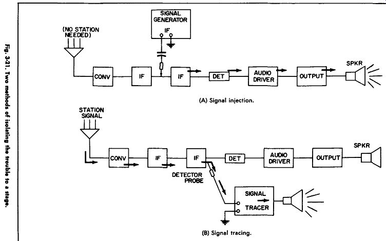
Fig. 3-21
One thing now becomes evident: The audio system of the radio being checked could be dead, and a station still be heard from the signal tracer in Fig. 3-21B. However, if the converter or one of the IF stages were dead, nothing would be heard. In other words, because the tracer has its own audio system, it can be used near the front-end of the radio first. It is then moved back toward the speaker, while we will listen for a point where the signal stops coming through, indicating a defect there. The station signal should become louder as the tracer is moved toward the output, since more stages of amplification are being added.
Test Points for Signal Tracers
Most signal tracers, unless designed for transistor radios, do not work when used too far forward in the radio. That is, if the tracer probe is placed on the antenna coil or converter stage, probably nothing will be heard. The first chance to pick up the signal should be at the collector of the 1st IF transistor, and even here it may be quite weak. However, from the 2nd IF collector to the speaker, a good signal can usually be heard.
One reason most signal tracers cannot be used too near the front-end is that there is a mismatch between the tracer and the transistor amplifiers in the radio. The tracer input has a fairly high impedance, whereas transistor impedance is relatively low. This makes it important to use the collector rather than the base leads for signal tracing, because the base impedance is usually much lower than the collector impedance.
So, although the match is not good at the collector terminals, it is better than trying to pick up signals at the base terminals.
This may seem to offer a severe disadvantage for most signal tracers. Actually, it doesn't. Assume a radio is very weak.
A signal tracer is first applied at the collector, or output, of the 1st IF stage. The radio being checked is tuned to a local station and is heard in the tracer as a weak signal. We know from previous experiments with our signal tracer that this is a normal output at this point. So we conclude that the converter and first IF stages are working properly. When the probe is moved one more stage to the right-to the 2nd IF collector no improvement is noted. In fact, the station almost disappears in the tracer speaker. It is obvious that our trouble must be in the 2nd IF stage. Instead of an increase in signal here, we got just the opposite.
The next question might be, "But what if no signal at all is heard at the 1st IF stage? How can I tell whether the converter or the 1st IF stage is at fault?"
The answer is, "You can't." But by making an additional test, you can quickly identify the defective stage. You have two choices-either use a signal-injection test to determine which stage does not pass the injected signal properly, or check the converter to see if the oscillator is functioning. If it is, chances are the converter is working properly.
So, to those who have had good luck with signal tracers, don't discard them. But we recommend learning the signal injection techniques, also, to supplement the signal tracer when it does not give sufficient information. This would be especially true in the front-end of a transistor radio.
Table 3-3 shows the test points where signal tracers can be used in most transistor radios. The most often-used test points are numbered 1 through 6. They are usually very easy to find because points 1, 2, 4, and 5 are transistor collector leads and 6 is the speaker.

--------------------- TABLE 3-3.
Major test points for signal tracers.
Test Point What To Expect
Converter Collector No Signal (unless tracer is specifically designed for transistor radios; see text)
1. 1st IF Collector Weak Signal
2. 2nd IF Collector Louder Signal
NOTE: A detector probe is used for the above, but not for the following tests. Change tracer from "RF" to "Audio" position.
3. Detector Output or Weak Signal Volume Control
4. . Audio Driver Collector Louder Signal
5. Audio Output Collector Louder Signal
6. Speaker Terminal Slightly Weaker Signal
-----------------------
Using the Signal Tracer
The signal tracer is quite easy to use, the benefit derived from it depending largely on the user's familiarity with his instrument. Signal tracers, like signal generators, vary considerably from model to model. Knowing what to expect to hear at each test point is the greatest aid in this type of trouble shooting.
The setting of the radio volume control will also affect the amount of signal heard in the tracer-especially when the audio stages are being checked. A good rule is to set it about halfway between minimum and maximum. Then use the gain control on the signal tracer to adjust the amount of signal at the tracer speaker. The reason for not turning the volume control to maximum is that distortion may be produced because a stage is overdriven, and this could throw the troubleshooter off the track.
Let us now take two sample problems to demonstrate the use of the signal tracer. (We will assume the batteries have already been checked.) The radio is dead. We turn its volume control halfway up and switch the tracer to the RF position. Then we use the detector probe in the IF stages as shown in Fig. 3-22. As the radio dial is tuned across the band, weak signals are heard at point 1 and good ones at point 2, indicating no trouble in the front-end or IF sections. We then switch the tracer to receive audio, and connect the leads to points 4, 5, and 6, where a good signal is picked up at each point.
Now, we know the signal is getting all the way back to the radio speaker. But, since nothing is heard from the speaker, we can conclude that it is probably defective.
Now let's assume a radio has distortion. Signal tracers can be very useful in isolating distortion, as will be seen in the following example.
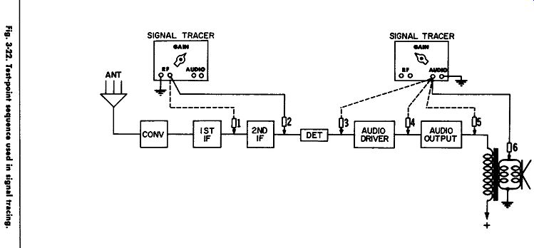
Fig. 3-22
We tune the radio to a station, and turn the volume control to about the normal listening level. A check at point 2 results in a clear, undistorted signal being heard in the signal tracer. A check at point 4, the audio-driver collector lead, still gives us a clear signal in the speaker of the tracer. However, when the tracer is moved to point 5, the collector of the output stage, the distortion is picked up.
This means it is probably being produced in the output stage, since this is the first point where it is heard. On the other hand, if the distortion was not heard at any of the test points, including point 6, we can conclude that the radio speaker is at fault.
Signal-Tracer Summary
Some of the important points about signal tracers are:
1. They can be used to trace distortion, provided the output stage is not overdriven by excessive volume.
2. They can be used for troubleshooting weak or dead radios.
3. The front-end of the radio must be checked before the audio system. This is the reverse of signal-injection tests, where the audio section is always checked first.
4. The signal tracer has certain limitations in the front-end of a transistor receiver. Because of mismatch between the tracer input impedance and the transistor output impedance, signals usually cannot be heard in the converter stage, and they may be weak in the 1st IF stage.
5. The tracer is usually used on transistor collector leads.
6. The success of a signal tracer depends largely on how familiar the operator is with his own instrument.