AMAZON multi-meters discounts AMAZON oscilloscope discounts
Most bridges operate at frequencies between 60 Hz and 20 kHz. But this does not mean that the bridge method is restricted to audio frequencies. On the contrary, specially designed and built bridges are operated at frequencies as high as the vhf end of the radio spectrum, in the conventional configuration, and into the microwave spectrum in special configurations. Thus, the radio-frequency bridge allows networks, antennas, transmission lines, and circuit components to be checked at their actual operating frequencies.
Radio-frequency bridges, or r-f instruments employing the bridge principle, are used to advantage in the laboratory, shop, and field, and generally their adjustment is no more difficult than that of low frequency bridges.
Courtesy General Radio Co.
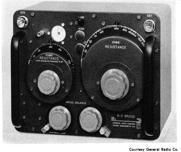
Fig. 6-1 . Professional radio-frequency bridge.
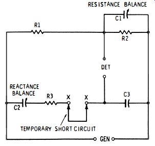
Fig. 6-2. Basic circuit of the r.f bridge.
6.1 REACTANCE / RESISTANCE RADIO-FREQUENCY BRIDGE
Fig. 6-1 shows a laboratory-type r-f bridge (General Radio Type 1606-A) which, like lower-frequency bridges, has separate balances for reactance (X) and resistance (R). The R and X values measured with this instrument may be used directly, or they may be employed in the calculation of r-f impedance (Z) . An external generator and external detector are required. The former must be a well-shielded r-f oscillator or signal generator, and the latter a well-shielded multi-band radio receiver or heterodyne detector. This bridge may be operated at frequencies from 400 kHz to 60 MHz. Resistance values between 0 and 1000 ohms may be read directly from the right-hand dial (Fig. 6-1 ); the left-hand dial indicates reactance values up to ±5000 ohms at 1 MHz. The latter dial is direct reading only at 1MHZ; at all other frequencies, its readings must be divided by the frequency in MHz.
Fig. 6-2 shows the basic circuit of the bridge. This is a version of the Schering bridge (see Section 3.6, Section 3). The use of variable air capacitors for each balance (C2 for reactance and C1 for resistance ) is an advantage, since strays, which are particularly disturbing at radio frequencies, may be minimized more easily in variable air capacitors than in the usual balancing rheostats and potentiometers.
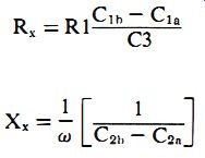
A substitution method is employed. In this procedure, the unknown terminals (X-X) first are short-circuited by means of a short, stout jumper, as shown in Fig. 6-2, and the bridge balanced by adjustment of capacitors C1 and C2. (The capacitor settings are recorded as C1a and C2a. ) Then, the unknown impedance is connected to the X-X terminals in place of the jumper, and the bridge is rebalanced. (The new settings of the capacitors are recorded as C1 h and C2b. ) The unknown resistance (Rx) and unknown reactance (Xx ) may be determined in terms of these settings. At null : and
R = R1 C1h - CIa x C3 X - -
1 [ 1 ] x
- W C2h - C2n
6-1
6-2
Fig. 6-3 shows the complete bridge circuit. In this arrangement, the resistance-balance capacitor (C2 corresponds to C1 in the basic circuit (Fig. 6-2). Similarly, the reactance-balance capacitor (C6) corresponds to C2 in the basic circuit. Separate capacitors (C 1 and C7) are provided for initial resistance and reactance balance, respectively. This enables the main dials (of C2 and C6 to be set to zero' for the initial balance, and direct readings of resistance and reactance then to be obtained. Switch S 1 enables the initial reactance balance to be made at either the high end or the zero end of the C6 dial. The internal compensating capacitors (C3 and C4 ) pre-adjust the circuit for this HIGH/LOW feature.
Note the elaborate shielding of the bridge, including the concentric DET and GEN jacks, J1 and J2. This shielding reduces the effects of strays and protects the bridge from external fields. The generator coupling transformer (T1 ) is a wide-band component, operating efficiently over the 400 kHz-60 MHz range. The high permeability of the ferrite core of this transformer permits the use of just a few turns in both the primary and secondary coils, and this markedly reduces internal capacitances.
6.2 SWR BRIDGE
A simplified version of the radio-frequency bridge is used for measurement of voltage standing-wave ratio (vswr, or swr). This type of measurement finds wide application in transmitter practice, and this kind of instrument is standard equipment in communications shops and transmitting stations . Because of its low cost and comparative simplicity, it is popular with amateurs and experimenters who may either build it or buy it factory-assembled or in kit form.
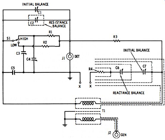
Fig. 6-3. Complete circuit of the r-f bridge.
(B) Equivalent bridge.
(A) Complete circuit.
Fig. 6-4. Bridge-type swr meter.
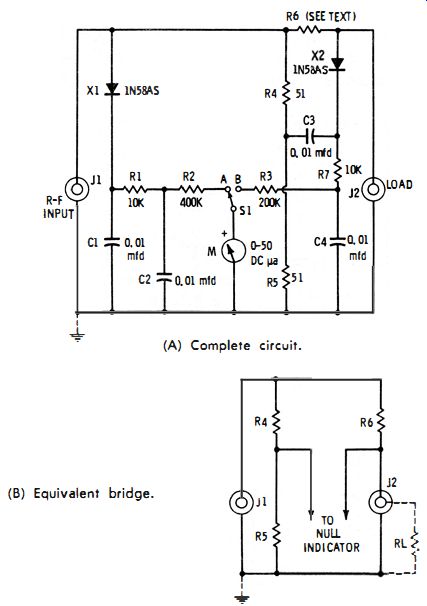
Fig. 6-4A shows the circuit of the swr meter. This instrument is convenient
for checking antennas, networks, and components at radio frequencies up to
100 MHz. The device under test (load) is connected to coaxial jack 12 by the
shortest possible leads, and the transmitter or signal generator is connected
to coaxial jack J 1. Meter M reads the input signal when switch S I is thrown
to position A, and the signal across the external load when S1 is thrown to
B. This meter is previously calibrated, in combination with diodes Xl and X2
and resistors R1, R2, R3, and R7, to read r-f volts directly. The bridge arms
consist of non inductive resistors R4 and R5 in one line, and non inductive
resistor R6 and the device (RL) under test (connected to jack J2 ) in the other
line ; see equivalent circuit, Fig. 6-4B).
All resistors must be 1-watt, 1% noninductive units. The resistance of R6 must equal exactly the impedance of the transmission line, network, antenna, or component connected to J2 for test; otherwise, the bridge will not null. (Common impedance values met in practice are 52, 75, 300, and 600 ohms.) When R4, R5 , and R6 have the exact specified values, the bridge will null at the selected "J2 impedance." That is, meter M will read zero when SI is at position B, and the bridge is driven by an r-f input voltage applied through jack J 1. Layout of the instrument must be carefully planned to minimize stray capacitance, inductance, and coupling, and fully shielded to prevent r-f pickup from the fields always present around transmitters.
When the instrument is in use, an r-f signal at the desired frequency is applied to the circuit through jack 11; a noninductive dummy resistor equal to RL (the impedance of the device being tested) is connected by the shortest possible leads temporarily to 12; a noninductive resistor equal to the impedance or resistance RL also is connected in the position of R6 ; and switch S1 is thrown to position A. Next, the output of the signal generator is adjusted for full-scale deflection of meter M, and the voltage indicated by M is recorded as E1. Switch S1 then is thrown to position B, whereupon the meter reading should fall to zero ; since R6 = RL. Then, the dummy resistor is removed from J2, and the device under test (RL) is connected in its place. Any reading of the meter at this point is recorded as E2. Finally, the standing-wave ratio is calculated :
6.3 R-F IMPEDANCE BRIDGE
6-3
(A) Complete circuit. (B) Equivalent bridge.
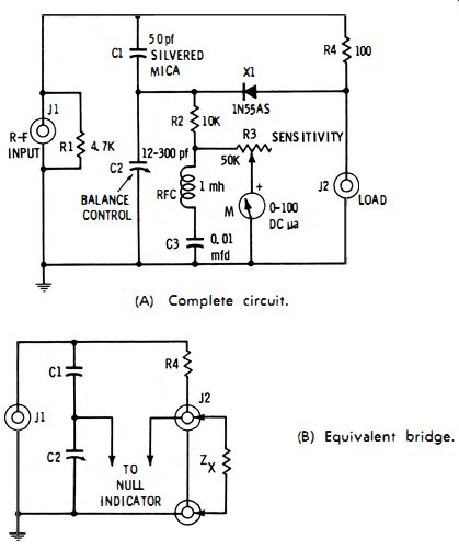
Fig. 6-5. R-f impedance bridge.
Fig. 6-5A shows the circuit of an r-f impedance bridge suitable for measuring the impedance of amateur and Citizens-band antennas, transmission lines, filters, and circuit components between 20 and 600 ohms at frequencies up to 50 MHz. After the instrument is calibrated, the impedance in ohms may be read directly from the dial of variable capacitor C2 (the balance control ). The null detector is a diode-type r-f voltmeter consisting of a miniature 1N55AS germanium diode (Xl ), resistor R2, rheostat R3, r-f choke RFC, and bypass capacitor C3. Rheostat R3 serves as a sensitivity control. Since M is used only as a null indicator, no voltage or current calibration is required. An r-f signal voltage from an oscillator or signal generator is applied to the circuit through jack J1. Finally, the unknown impedance is connected by the shortest possible leads to jack j2.
The arms of the bridge are capacitors C1 and C2 in one line, and resistor R4 and the unknown impedance (Zx, connected to jack 12 ) in the other line (see equivalent circuit, Fig. 6-5 B). Variable capacitor C2 is adjusted to balance the bridge. At null , the unknown impedance may be calculated in terms of resistance R4 and capacitances C1 and C2 : Zx = C1R4/C2

6-4
The simplest way to calibrate the instrument is to balance the bridge separately with as many noninductive resistors (between 20 and 600 ohms ) as are available connected successively to jack 12 with short leads, and to inscribe the dial of variable capacitor C2 with these resistance values.
After initial calibration, use of the instrument is simple:
1. An r-f test signal of desired frequency is injected into the circuit via jack 11.
2. The device under test (antenna, transmission line, filter, or circuit component ) is connected by the shortest possible leads to jack 12.
3. Variable capacitor C2 is adjusted to balance the bridge, and rheostat R3 is adjusted to increase the sensitivity of the meter as null is approached.
4. At null, the unknown r-f impedance is read directly from the calibrated dial of C2.
When the bridge is used in the adjustment of an impedance Z (e.g., adjustment of a network or load device ), the C2 dial is set to the desired impedance value, and the external impedance (Z) is then adjusted for null, as indicated by meter M.
6.4 BRIDGE-TYPE UHF ADMITTANCE METER
Fig. 6-6 shows the basic arrangement of a coaxial-type admittance meter (General Radio Type 1602-B ) which gives direct readings of conductance and susceptance of antennas, transmission lines, and components at test frequencies from 40 to 1500 MHz. This instrument requires an external uhf signal generator and external heterodyne detector.
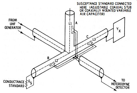
Fig. 6-6. Bridge-type uhf admittance meter.
The instrument consists of a system of joined coaxial lines. The unknown admittance (Y x ) is connected to line C, a conductance standard (Gs) to line B, and a susceptance standard to line A. The conductance and susceptance standards screw directly on the ends of line B and line A, respectively.
Current in each of the three lines is sampled by means of a rotatable loop (L1, L2, L3 ). The three loops are connected in parallel and to the detector. A dial attached to L1 read directly in susceptance (millimhos ), one attached to L2 reads directly in conductance (millimhos ), and one attached to L3 reads a multiplying factor (from 1.1 to infinity). With the bridge energized by the generator, the loops are adjusted for balance, as indicated by the detector. At null, the susceptance and conductance of the device under test are read from the settings of the L1 and L2 dials, respectively, and these values are multiplied by the setting of the L3 dial.
If a suitable constant-impedance adjustment line (such as General Radio Type 874-LK20L) is connected between the unknown (Yx) and line C, and this line is set to one-quarter wavelength at the generator frequency, the two main dials will read impedance components of the device. That is, the L1 dial will read reactance and the L2 dial series resistance.