AMAZON multi-meters discounts AMAZON oscilloscope discounts
A few bridge circuits are frequency sensitive, i.e., their null setting changes with generator frequency. This necessitates that a single test frequency be accurately maintained if direct-reading dials are used on such bridges. It also means that a frequency term often appears in formulas for calculating inductance, capacitance, and equivalent resistance.
While frequency sensitivity can be somewhat of a nuisance in capacitance, resistance, and inductance bridges, this property may be utilized for · the measurement of frequency if al of the bridge arms are filled and the bridge is balanced for frequency. In such an instance, the balance adjustment may be made direct reading in frequency instead of in R, C, or L. The resistance, capacitance, and/or inductance values in the bridge arms usually can be known with high precision, so that the bridge becomes a useful device for accurate and simple measurement of frequency.
Measurements of this sort are usually limited to frequencies no higher than 20 kHz, since small stray reactances blunt the null response and may even bypass the signal around the bridge at higher frequencies.
Aside from conventional bridges, some non-bridge null circuits function reliably for frequency measurement and sometimes are preferred to bridges (see Section 9) .
7.1 SERIES-TYPE RESONANCE BRIDGE
Fig. 7-1 shows the circuit of a resonance bridge of the series type. This bridge may be balanced only at the frequency determined by inductance L1 and capacitance C1 in one arm of the circuit. At this resonant frequency of the L1-C7 1 combination, the inductive reactance cancels the capacitive reactance, and only the inherent resistances of the inductor and the capacitor remain in the upper left arm of the bridge, making the circuit a four-arm resistance bridge at that one frequency. At null, the unknown frequency is :
fx = 1/ (2 pi V LC) where, C is the value of C1 in farads, f is in Hz, L is the value of L1 in hy pi equals 3. 1416.
7-
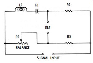
Fig. 7-1 . Series-type resonance bridge.
Frequency coverage may be provided by making C1 variable for tuning, and by switching L1 to appropriate values to change ranges.
(Conversely, a d-c-tuned variable inductor might be employed for tuning, and capacitors switched to change ranges.) Since high capacitances are needed in the audio spectrum, a variable C1 would, for practical purposes, be a capacitor decade.
For sharp null response, both L1 and C1 must be high-Q components. This calls for a low-resistance inductor of toroidal construction and for a mica capacitor.
7.2 SHUNT-TYPE RESONANCE BRIDGE
Because the impedance arm in Fig. 7-1 is a series-resonant circuit, the current through this arm and the one containing resistor R1 is maximum at the resonant frequency and can reach high levels.
In some inductors, especially when high input-signal voltage and low R1 resistance are unavoidable high current can cause distortion.
In Fig. 7-2, the impedance arm has been changed to a shunt connection of inductance and capacitance (parallel-resonant circuit ).

Fig. 7-2. Shunt-type resonance bridge.
Here, at resonance the current through this arm and the one containing resistor R 1 is minimum, approaching zero for high-Q capacitors and inductors.
In all other respects, the shunt-type bridge is identical to the series type. The balance equation is the same (see equation 7-1 ).
7.3. WIEN BRIDGE
The Wien bridge (Fig. 7-3 ) is very desirable for frequency measurements, since it uses only capacitors and resistors and can be made very compact, and since its balance equation can be greatly simplified.
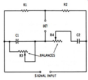
Fig. 7-3. Wien bridge.
In this circuit, there are two resistance arms (R1 and R2 ) and two adjustable impedance arms (C1-R3 and C2-R4 ). One impedance arm must have its resistance and capacitance in parallel (like C1-R3) and the other one must have its resistance and capacitance in series (like C2-R4). Alternatively, resistors R3 and R4 may be fixed, and capacitors C1 and C2 variable.
Both variable elements must be adjusted to balance the bridge, and null may be obtained for a large combination of R and C values : where, C is in farads, fx is in Hz, R is in ohms, pi equals 3.1416.
£:1: = 1/(2 pi\1R3R4CIC2)
7-2
If a dual rheostat is used for simultaneous adjustment of the two variable resistances so that R3 equals R4 at all settings, if resistance R2 is made twice R1, and if the capacitors are matched so that C1 equals C2, the balance equation can be simplified to:
fx = 1/ (2 pi R3C1)
7-3
This results in a simplified circuit which has often been used as a highly practical audio-frequency meter.
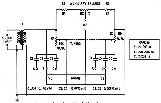
Fig. 7-4
Fig. 7-4 shows the complete circuit of a Wien-bridge audio-frequency meter which covers the range from 20 Hz to 20 kHz in three steps : (A) 20-200 Hz, (B) 200-2000 Hz, and (C) 2-20 kHz.
The single tuning control is the dual 10,000-ohm wirewound balancing rheostat (R4-R5) . The three ranges are selected by double-pole, three-position switch S1-S2 which switches capacitors in identical pairs (C1 -C4, C2-C5, and C3-C6) . The dial attached to rheostat R4-R5 is calibrated to read directly in Hz on the lowest (20-200-Hz) range, and the switch settings then multiply this range by 1 (range A), 10 (range B), and 100 (range C). Potentiometer R2 is an auxiliary control which allows the null to be sharpened without upsetting the frequency reading of the R4-R5 dial. Resistors R1 and R3 provide the 2: 1 ratio required for simplification of the bridge balance. These resistors and all of the capacitors must be accurately rated (1% or better) . A shielded input transformer (T1 ) is required. The detector may be an oscilloscope, a-c vtvm, magic-eye tube, high-impedance a-c null detector, or high-impedance headphones with or without an amplifier.
The instrument is calibrated best by feeding as many accurate frequencies as are available between 20 and 200 Hz into the circuit via the SIGNAL INPUT terminals, and balancing the bridge by adjustment of rheostats R4-R5 and potentiometer R2, with switch S1-S2 in its position A. The rheostats and potentiometer R2 should be adjusted alternately for the deepest obtainable null. At each null, the corresponding frequency is inscribed on the R4-R5 dial. Only this one range need be calibrated; if capacitors C1-C6 are accurate, the two higher frequency ranges will track automatically.
7.4 SUPPLEMENTARY USES OF FREQUENCY BRIDGES
Besides frequency identification, there are numerous other applications of frequency-sensitive bridges-all of which exploit the ability of this type of bridge to null at one frequency. Thus, the bridge can function as a band-elimination filter (notch filter), heterodyne suppressor in radiophone reception, interference eliminator in radio telegraph reception, fundamental remover in audio distortion measurements, and tuning network in audio amplifiers and oscillators.
In Section 10 will be found detailed explanations of some of the supplementary applications of frequency-sensitive bridges.