AMAZON multi-meters discounts AMAZON oscilloscope discounts
A specialized version of the null method permits measurement of the amplification parameters of vacuum tubes and transistors. Because these parameters are determined in this way in terms of precision resistances, they often are indicated more accurately than when meters alone are used.
Some bridges used for tube and transistor testing are hybrids.
All, however, exploit the advantages inherent in the null method.
Of these instruments, the classic vacuum-tube bridge is seldom found outside the laboratory, meter-type tube testers commonly being used for nonengineering testing in the field. But bridge-type transistor testers may be found both in the laboratory and in the field.
8.1 VACUUM-TUBE BRIDGE
Fig. 8-1 shows a vacuum-tube bridge (General Radio Type 11 61-B). In instruments of this type, the tube under test provides one or two of the arms of a bridge, which then is balanced in the presence of a selected combination of applied operating and signal voltages. The tube parameter of interest (such as plate resistance, amplification factor, or transconductance ) is read from the values of the bridge resistances at null. Under certain conditions, the bridge balance control is direct reading in the parameter. The a-c and d-c operating power for the tube is obtained from an external supply, and an external generator and detector are used.
Courtesy General Radio Co.
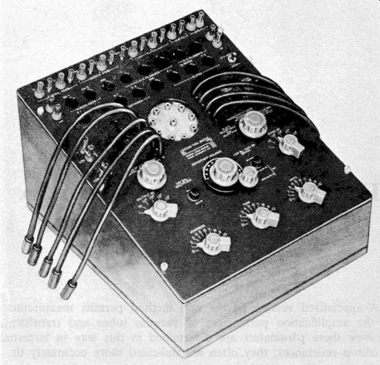
Fig. 8-1. Professional vacuum tube bridge.
By means of selector switches and/or patch cords, various circuits are set up in the bridge for testing the tube for the desired parameters. Typical circuits of this sort are described in the following Sections 8.2, 8.3, 8.4, and 8.5, and illustrated in the corresponding figures. While, for simplicity, a triode tube is shown in each of these circuits, multielement tubes also may be tested, provided proper voltages are supplied.
8.2 TUBE PLATE RESISTANCE
Fig. 8-2 shows the circuit for measuring the dynamic plate resistance (Rp) of a vacuum tube. Here, tube VI (under test ) is supplied with grid voltage by variable d-c supply Ee, and with plate voltage by variable d-c supply Eb• Plate current (Ip) is adjusted to the desired operating level, as indicated by d-c milliammeter M I, by varying Eb• Plate-to-ground and grid-to-ground d-c voltage may be read with a high-resistance d-c voltmeter or d-c vtvm. The effect of tube capacitance in the bridge is compensated by adjustment of a vario-meter-the phase balance, T2.
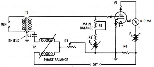
Fig. 8-2. Circuit for tube plate resistance.
The input signal (normally 1 kHz) is applied through the shielded transformer, T1. The output signal is indicated by an a-c null detector connected to the DET terminals.
Rheostat R3 is set to a resistance equal to 10 times the amplification factor of the tube, and the bridge is balanced by adjustment of rheostat R1. If R4 is precisely 1000 ohms, then at null the plate resistance may be found in terms of R1 :
Rp = 100 R1
8-1
8.3 TUBE AMPLIFICATION FACTOR (DC)
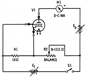
Fig. 8-3. D-c circuit for tube amplification factor.
Fig. 8-3 shows the circuit for measuring the static amplification factor (d-c p,) of a vacuum tube. Here, tube VI is supplied with the desired level of plate voltage by variable d-c supply Eb, and with grid voltage by the voltage drop produced across resistor R 1 by current flowing from d-c signal source E1 through the R1-R2 line.
Resistance R1 is a low value, such as 10 ohms. Plate current may be read with an inserted d-c milliammeter, M1, and plate and grid voltages with a d-c vtvm.
When switch S1 is open, the grid voltage is zero and the plate voltage consist solely of Eb. But when S1 is closed, E\ produces across R1 a voltage drop which becomes the grid voltage (Eg), and across R2 a voltage drop which adds to Eb to increase the plate voltage. Now, by definition, the amplification factor, !-", is the ratio of a plate-voltage change (dEp ) which produces the same change (dIp) in plate current as a grid-voltage change ( dEg). But because of the amplification provided by a tube, the grid voltage ' is !-" times as effective as the plate voltage in producing a given plate-current change.
Operation of the circuit consists accordingly of comparing these elements. This consists of opening switch S1 and noting the static plate current, I.,. Then S1 is closed, whereupon Ip increases because of the application of grid voltage. Rheostat R2 next is adjusted to bring Ip back to its original "zero" value (a kind of null adjustment) . At this point, R2 = uR1, and:
u = R2/R1
8-2
8.4 TUBE AMPLIFICATION FACTOR (AC)
The static value of !-" afforded by the d-c bridge test described in the preceding section is often considered an inadequate indicator of tube performance, since, except in steady-state d-c amplifiers and certain control circuits, tubes usually operate under dynamic conditions-that is, with a-c signals. A dynamic test of amplification factor thus may be considered more suitable. Fig. 8-5 shows a circuit for the bridge measurement of this parameter.
This arrangement is similar to the dc circuit of Fig. 8-4, but here the a-c signal voltage, supplied through shielded transformer T2, develops an a-c grid voltage across 10-ohm resistor R1, and an a-c component of plate voltage across rheostat R2. Balance is indicated by an external a-c null detector connected to . the DET terminals. (The input circuit of this detector must provide a low resistance path, through resistor Rd, for the d-c plate current of tube V1.) Plate rheostat R2 and phase-balance vario-meter T1 are adjusted alternately for null. At null, the amplification factor is the ratio of R2 to R 1, a relationship which is simplified because the resistor R1 is equal to 10:
u = 0. lR2
8-3
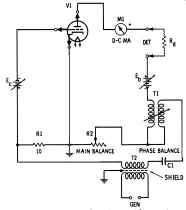
Fig. 8-4. A-c circuit for tube amplification factor.
8.5 TUBE TRANSCONDUCTANCE
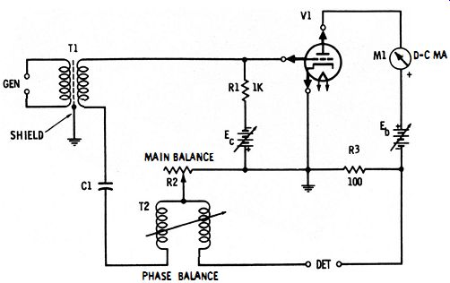
Fig. 8-5. Circuit for tube transconductance.
Fig. 8-5 shows the circuit for bridge measurement of dynamic transconductance (gm) of tube V1. Here, the desired level of plate voltage is provided by variable d-c source Eb, and grid voltage by variable d-c source Ee. An a-c grid-signal voltage results from the voltage drop across R2, produced by generator current flowing through R2. Capacitor CI provides d-c blocking in the grid circuit.
The bridge is balanced by alternate adjustment of rheostat R2 and phase-balance vario-meter T2. If the plate resistance (Rp) of the tube is high, compared with the 100-ohm resistance, R3, the setting of rheostat R2 is 100,000 times IL/Rp. And since gm = IL/Rp, the transconductance becomes : where, gm is in mhos, R2 is in ohms.
gm = R2/ 100,000
8-4
To convert to micromhos, multiply gm by 1,000,000.
8.6 TRANSISTOR BRIDGE
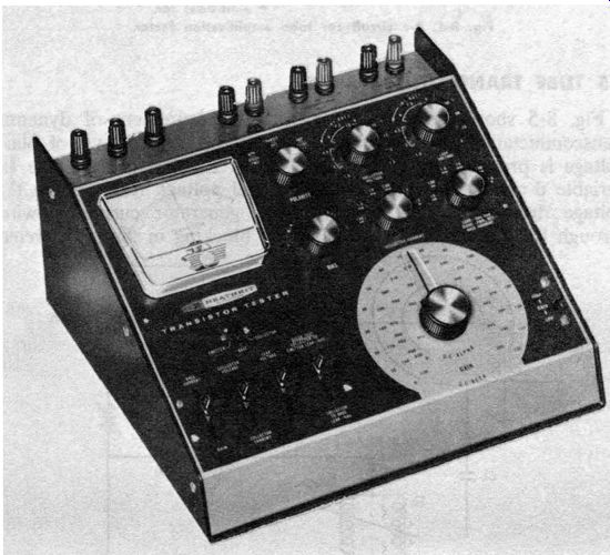
Fig. 8-6. Bridge-type transistor tester.
Fig. 8-6 shows a representative transistor bridge (Heathkit Model IM-30) which is available factory wired or as a kit. This instrument operates from internal batteries or from an external power supply.
Its center-zero meter is used as the null detector and also as a voltmeter and current meter for checking various transistor voltages and currents.
Selector switches and key switches enable the various functions of the instrument to be obtained, and the dial of the balance control is graduated directly in d-c alpha and d-c beta, the amplification factors of transistors.
Transistor bridge circuits are described in Sections 8.7 and 8.8.
8.7 D-C AMPLIFICATION FACTOR OF TRANSISTOR
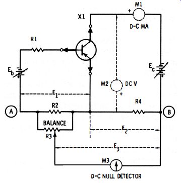
Fig. 8-7. Circuit for d-c amplification factor of transistor.
The current amplification factor (f3-beta or hte ) of a transistor is comparable to the voltage amplification factor (fL) of a vacuum tube. Beta is the ratio of collector-current change to the base-current change which produces it (i.e., f3 = dIe/dIb ). Static (d-c ) beta and dynamic (a-c ) beta both may be measured with bridge-type circuits.
Fig. 8-7 shows a d-c circuit. In this arrangement, PNP transistor X 1 is supplied with base current from variable d-c source Eb through limiting resistor R1, and with collector current from variable d-c source Ee. The polarity of each of these sources must be reversed for an NPN transistor.
If desired, collector current may be read with d-c milliammeter M3, and collector voltage with high-resistance d-c voltmeter M2. D-c meter M3 is a center-zero galvanometer or other d-c null detector.
Base-current flow develops a voltage drop (Ed across resistor R2, and collector-current flow develops a voltage drop (E2) across resistor R4. If either of these resistors is varied and the other held constant, El can be made equal to E2, whereupon voltage Ea between points A and B will be zero. At this null point, beta is equal to E:dEt , and therefore is proportional to R4/R2. Since it is impossible to vary R2 without disturbing the operating point of the transistor, a potentiometer, R3, whose resistance is much higher than that of R2 is provided for sampling the voltage across R2 and balancing it against E2. In this way, R2 and R4 may be kept fixed and their ratio changed for various beta ranges.
At null (E3 = 0), the amplification factor may be determined in terms of the base and collector voltages:
8-5
The dial of potentiometer R3 may be graduated for direct reading of beta according to this ratio. It may be calibrated also on the basis of the resistance ratio (i .e., the ratio of R4 to the resistance of R2 and R3 in parallel ). The dial may also be graduated in alpha, a (current amplification factor of the common-base configuration) on the basis of a = {3/{3 + 1.
8.8 A-C AMPLIFICATION FACTOR OF TRANSISTOR
Just as the dynamic (a-c) value of the tube amplification factor is sometimes preferred to the static value, so is the a-c beta of a transistor sometimes preferred to the d-c value.
Fig. 8-8 shows a bridge circuit for measuring the a-c amplification factor.
This arrangement is similar to the d-c circuit described in the preceding section, except that an a-c test signal is supplied through transformer T1, and an external a-c detector (oscilloscope, a-c vtvm, magic-eye tube, or high-impedance headphones ) is required.
D-c operating voltage is supplied to transistor X1 under test by variable d-c supply B. A double-pole, three-position reversing switch (S1-S2 ) turns the voltage OFF (center ), ON positive for NPN transistors (lower), or ON negative for PNP transistors (upper ). C1 and C2 are d-c-blocking capacitors. A 1-kHz signal is desirable and may be obtained from an audio oscillator; however, many simple versions of this circuit use a 60-Hz signal taken from the power line, with TI being a filament transformer. Because R3 is a very high resistance, the base-current generator is essentially constant current in nature. Another high resistance, R2, determines the d-c base bias. It is upon this bias that the much smaller a-c test signal is superimposed.
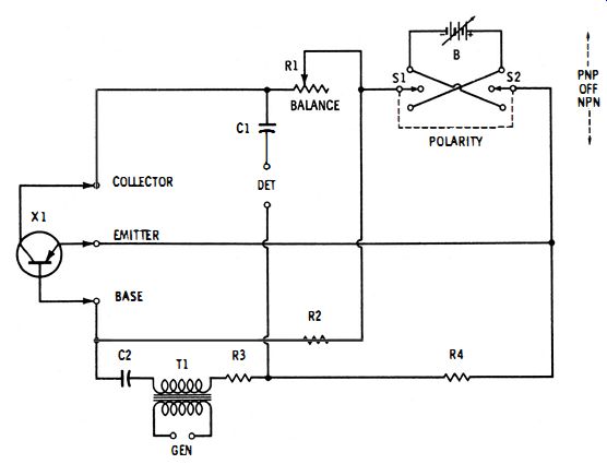
Fig. 8-8. Circuit for a-c amplification factor of transistor.
When the circuit is in operation, the transistor amplifies the a-c base current, and the resulting a-c collector current develops an a-c component across rheostat R1; this component is opposite in phase to the a-c drop across resistor R4. When R1 is adjusted to make these out-of-phase voltages equal in amplitude, the output signal at the DET terminals is minimum; i.e., the bridge is balanced. At this null point, the current amplification is proportional to the ratio of the two resistances:
Beta= R4/R1
8-6
The dial of rheostat R 1 accordingly may be graduated to read directly in beta. It may be calibrated to read also in alpha, a (current amplification factor of the common-base configuration ) on the basis of a = f3/ f3 + 1.
Typical circuit constants are: B, 1%-12 volts; C1, 0.05 mfd; C2, 0.1 mfd; R1, 5K 1 %; R2, 1K wirewound; R3, 100K; and R4, 250K.