AMAZON multi-meters discounts AMAZON oscilloscope discounts
A bewildering array of capacitor types have evolved from the simple Leyden jar (Fig. 3-1). Some are flat, some are round, some square-in fact they are to be found in just about every shape imaginable. Why this deviation from the original has taken place will become apparent as we investigate their development and construction.
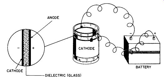
Fig. 3-1. Leyden jar capacitor.
BASIC DEVELOPMENT
Leyden jars were the basic capacitors used in early experiments with electrical energy. Even today they offer several definite advantages. In the first place, they are very dependable. Second, it is relatively easy to change the value by adding or removing metal foil. Third, they introduce very few undesirable properties, such as inductance, etc., into an experiment. However, they are bulky; furthermore, there is a definite limit to the amount of capacity attainable.
After all, a glass jar can be made just so thin before it be comes too fragile to be handled.
The next logical development in capacitor design was the flat plate type. It is considerably smaller than the equivalent Leyden jar because there is no wasted space in the center. However, it is still extremely bulky and awkward to handle, especially when larger capacitances are involved.
Of course, flat-plate capacitors can be ganged into parallel circuits, as shown in Fig. 3-2, to provide a very definite saving in space.
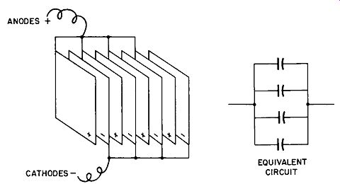
Fig. 3-2. Flat paralleled plate capacitor.
Like the original Leyden jar, the first flat-plate capacitors also used a glass dielectric. These units were superior to the jar, being much more compact; but because of their glass dielectric, they still were quite fragile. It was soon discovered that the glass could be eliminated if the plates were moved farther apart. We now know why--because air can be used as a dielectric, but being less effective than glass, the distance between plates must be greater in order to provide the same resistance against voltage breakdown.
This is where matters stood until the dawn of radio. Development then followed in rapid succession--first the mica capacitor, then paper, electrolytics, ceramics, and now plastics.
AIR CAPACITORS
Although air is a poor insulator, it is still highly useful as the dielectric in a capacitor because its power factor is almost nil and its stability is excellent. Furthermore, it's free.
The capacity ratings of air-dielectric capacitors range from about 3 mmf, to above 330 mmf. Voltage ratings reach a practical limit at about 30,000 volts DC. Air capacitors may be either fixed or variable, but their primary advantage is that they are easy to construct.
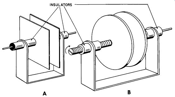
Fig. 3-3. Fixed and variable air dielectric capacitors.
Fig. 3-3 shows the basic arrangement of a simple single plate air capacitor. The plates of the fixed unit (Fig. 3-3A) are insulated from the supporting frame by an appropriate material. Fig. 3-3B shows a simple variable air capacitor.
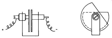
Fig. 3-4. Basic constant-gap variable air capacitor.
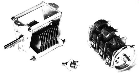
Fig. 3-5. Variable capacitors.
A screw thread varies the distance between the two plates and thus increases or decreases the capacitance. This arrangement has a disadvantage, however--the resistance to voltage breakdown increases or decreases inversely with capacitance. Therefore, its application is somewhat limited.
The much more common variable air capacitor is shown in Fig. 3-4. This is the constant-gap type, in which the capacitance is varied by exposing more or less of the plate surfaces to change the area ratio between plates. Since the plates remain the same distance apart at all times, the resistance to voltage breakdown never changes. From this very simple type, the design can be varied in ways limited only by imagination. Multiple plates may be added to increase the capacitance, and their shape designed to provide the precise variation required--semicircular plates will provide linear capacitance variation proportional to the amount of rotation. Other shapes can provide linear frequency variation proportional to amount of rotation. Representative types, used principally in tuning and trimming applications, are shown in Fig. 3-5.
The rotor plates can be made of virtually any conducting material, but aluminum is the most common. Other metals such as brass or copper are sometimes used, but are subject to corrosion unless properly protected by plating. Silver plating is often used to provide a lower surface resistance, and nickel plating is used if extreme corrosion is likely to be encountered.
Although air-dielectric capacitors are among the poorest, when judged on the basis of size versus capacitance, they still offer definite advantages over other types. They are extremely stable, are only slightly affected by temperature changes, have a very low power factor, and their life is limited only by physical damage or by failure of the supporting insulators. Other than size, their principal disadvantages are that they are very susceptible to changes in humidity, which can cause the voltage to arc across the plates. Also, the plates may vibrate at high frequencies and cause the capacitance to fluctuate.
In an effort to ward off atmospheric effects, some capacitors are placed in sealed cases which have been evacuated or filled with an inert gas. In some transistor radios they are encased in plastic, primarily to prevent dust particles from forming stray conductive paths and thus affecting circuit performance.
PAPER AND FILM CAPACITORS
As more and more uses for capacitors unfolded, the need for units with larger capacitance values became more pressing. There is a practical limit to the physical size of a Leyden jar or flat-plate type. Thus, the search for more compact units resulted in further work on the development of dielectrics. It was discovered that high-quality Kraft paper, when impregnated with oil or wax, was an excellent dielectric. Furthermore, the paper, being flexible, could be rolled up tightly to form a most compact unit.
The actual construction of paper capacitors varies from one class to another, but the basic method consists of two metal foils separated by tightly rolled layers of paper. During manufacture the entire assembly is vacuum-dried to eliminate any moisture, and is then impregnated with oil, wax, or some synthetic material to increase the voltage rating. The unit may be housed in a cardboard tube or in a metal sleeve, or it may be molded into a plastic case for greater protection against moisture infiltration.
The paper dielectric is usually made up of many layers of thin paper, rather than a few layers of thicker paper. The former has a lower voltage stress-in other words, the capacitor can withstand a higher voltage.
Even the highest-quality papers will contain minute voids (microscopic openings) or foreign particles of conductive material. (Thicker stock would have fewer voids but just as many or more conducting particles.) The multiple layers of thinner paper greatly lessen the chance that these voids will line up, or that foreign particles will form a straight through conductive path. Thinner stock also insures faster and more thorough drying, and a more even wax or oil impregnation.
Wax, mineral oil, and various synthetic compounds are the three basic impregnates. This is generally the order of final capacitor quality, too. Of the three, wax-impregnated types have the most restricted temperature range and lowest voltage rating (because it is difficult to completely impregnate the paper), and mineral oil provides the greatest temperature-capacitance stability. On the other hand, synthetics have higher dielectric strengths than mineral oil (making possible smaller capacitors), but their temperature characteristics are not as good.
Fig. 3-6 illustrates the basic construction of a paper capacitor. Notice that tabs ( one for each plate) provide connecting points for the pigtail leads. This is the simplest method of doing the job-but the least satisfactory from a performance standpoint. The use of multiple instead of single tabs, or the extended-foil method, is superior.
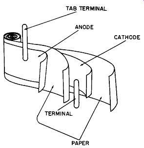
Fig. 3-6. Basic paper capacitor construction.
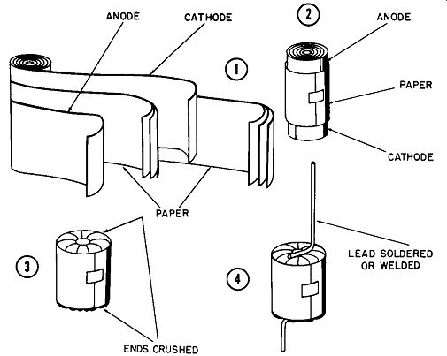
Fig. 3-7. Extended foil paper capacitor construction.
Fig. 3-7 shows the basic construction of an extended-foil capacitor. It is essentially noninductive, since all layers for one plate are mutually joined at one end. Another advantage of this construction is its lower internal resistance. However, it is more expensive and great care must be exercised during manufacture to avoid shorting the plates when the ends are crushed.
Paper capacitors as a class should not be operated at high temperatures, due primarily to the nature of the paper it self. The minute impurities found in paper pulp tend to become more chemically active as temperatures rise and, in combination with the inevitable impurities in the plates and impregnants, lead to premature failure.
In their ability to withstand high voltages, paper capacitors are exceeded only by mica types. Mineral-oil units, in particular, exhibit excellent capabilities in this direction.
Their corona-starting potentials are on the order of twice the rated voltage. Thus, these units are often used in buffer applications, where high transient-voltage surges would quickly result in the failure of other types.
Plastic films such as polystyrene or Mylar are rapidly replacing paper as a dielectric, especially for general purpose use. Plastic is much denser than paper, and contaminating foreign particles are practically nonexistent.
Therefore, plastic units can generally be made smaller than paper units of equivalent value. Plastics can withstand higher temperatures and are considerably more stable than paper. Because of their lower corona-starting voltage, however, plastic units should never be used in high-voltage buffer applications.
Polystyrene types have better temperature characteristics than Mylar, but are limited to +85°C, whereas the latter can be operated up to + 130°C. Where unusually high-voltage performance is required, oil-filled plastic capacitors may be used. Unlike paper, plastic is relatively nonporous and must be kept immersed in oil. (Some paper types are oil immersed also, primarily to improve their heat-dissipation characteristics.) A third type of capacitor, actually a combination paper and plastic, is the metallized paper type. A thin metal film (usually vacuum-plated aluminum) is deposited on the paper, which is then rolled alternately between layers of Mylar. The metal film provides a "self-healing" property--it burns away when a flashover occurs and thereby opens the path for potential short circuits. This can be a disadvantage in low-noise circuits, however; the arcing will produce spurious signals, especially if the voltage is too low to burn completely through the film. Nevertheless, the paper and plastic combination make possible very small capacitors having excellent over-all performance characteristics.
Plastic film capacitors are customarily housed in cardboard tubes or metal containers, or are molded in plastic.
Because of their relatively poor moisture resistance, card board containers are gradually becoming extinct for capacitors used in high-performance equipment. Today, the molded plastic case is the most common housing for both paper and film types. It may be either a one-piece arrangement or a tube sealed at both ends. For a true hermetic seal, it is necessary to house the capacitor in a metal case with a glass-to-metal seal. Use of this latter type is generally confined to computers and other high-reliability equipment.
In addition to a nominal voltage rating, paper capacitors have a surge voltage rating beyond which they should never be exposed-not even during tests. This rating is an insurance factor-it should never be reached. Remember that if you pretest a paper capacitor at-or even near-its surge voltage, you are practically asking for a failure. Always test paper capacitors at their rated nominal (working) voltage, never above it.
MICA CAPACITORS
Mica capacitors have been present in the electronics field for many years, but are gradually being replaced by the ceramic or glass types. Micas share the same generally poor size-to-capacitance ratio as all other flat capacitors. They are considerably smaller than the air type, however--primarily because, as a dielectric, mica is nearly seven times better than air. The fact that mica can be sliced quite thinly adds appreciably to the amount of capacitance attainable from a given plate area. Furthermore, mica, being relatively impervious to humidity and moisture, makes possible a very stable capacitor.
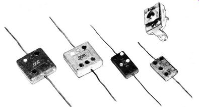
Fig. 3-8. Mica capacitors.
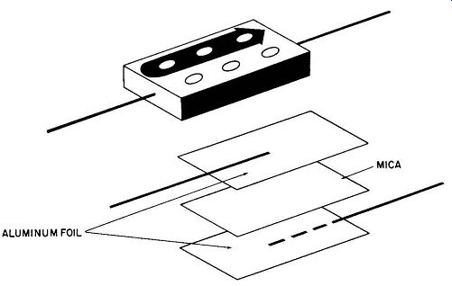
Fig. 3-9. Basic mica capacitor construction.
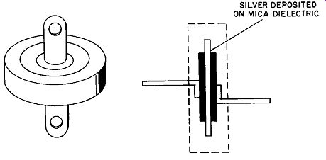
Fig. 3-10. Button silver-mica capacitor construction.
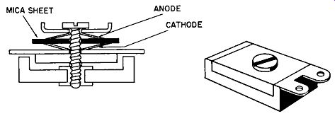
Fig. 3-11. Variable mica capacitor construction.
Mica capacitors are available with values ranging from 1 mmf to 1 mfd, and with voltage ratings as high as 35,000 VDC. Both fixed and variable types are made in two broad styles-foil and deposited silver. (See Fig. 3-8.) A foil mica capacitor, shown in Fig. 3-9, consists of a thin slice of mica sandwiched between two thin aluminum plates, plus a molded Bakelite case for protection. The foils and mica dielectric are built up in alternate layers (the more layers, the higher the capacitance) to produce a set of essentially paralleled capacitors.
A silver mica is similar to the foil type, except the silver is deposited directly onto the mica sheet. The more intimate contact between plate and dielectric results in increased capacitance and improved stability. There is, however, some danger that particles of silver will migrate through the mica under a high-voltage stress situation, especially if the slightest amount of moisture is present. Under these conditions, silver mica capacitors have been known to fail in minutes.
Button micas resemble the molded rectangular type, but are more fragile. (See Fig. 3-10.) Their principal advantages are a lower inductance and a very high leakage resistance.
Variable mica capacitors (Fig. 3-11) are common in trimmer applications. The capacitance is raised by tightening the screw to bring the plates closer together, and vice versa.
Because trimmers are exposed, mica is especially effective as a dielectric since it is relatively impervious to moisture.
CERAMIC CAPACITORS
Ceramic capacitors are among the most versatile of all, primarily because the dielectric can be made to give such a wide variety of results. The most common ceramic capacitor is the disc, although tubular and rolled types are also available. Fig. 3-12 illustrates several common ceramics.
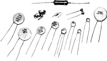
Fig. 3-12. Ceramic capacitors.
The capacitance ratings of ceramics range from 0.5 mmf to over 0.1 mfd. Voltages range as high as 30,000 VDC, with surge voltages up to 40,000 VDC. The disc and rolled styles are available as fixed capacitances only, but the tubular comes in both fixed and variable units. (There is one which, although essentially a disc, is available as a variable trimmer.) Ceramics offer a good size-to-capacitance ratio, in addition to some other valuable characteristics we will learn about.
Disc ceramics have similar capacitance values, but lower inductances, than mica types of corresponding values. The four types are general-purpose, temperature-compensating, temperature-stable, and frequency-stable. Each of these four broad types has characteristics which suit them to particular applications.
General-purpose types can be used in place of most general-purpose mica, tubular ceramic, or molded paper types in filter, bypass, or coupling circuits. The construction in Fig. 3-13 is common to all disc ceramics.
SILVER DEPOSITED CONDUCTORS
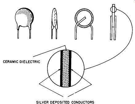
Fig. 3-13. Disc ceramic capacitor construction.
Their temperature versus capacity curve is similar to the one in Fig. 3-14. Note that it is merely representative of actual curves; the exact curve for the capacitor in question must be obtained from the manufacturer.
Temperature-compensating disc ceramics can survive temperatures ranging from -40°C to +85°C with virtually no change in capacitance, whereas the value of other units will change from +15% to -10% over the same tempera ture range.
The exact variation in capacitance to be expected from a temperature-compensating capacitor is stated as so many parts per million for each degree centigrade of temperature change between +25°C and +85°C.
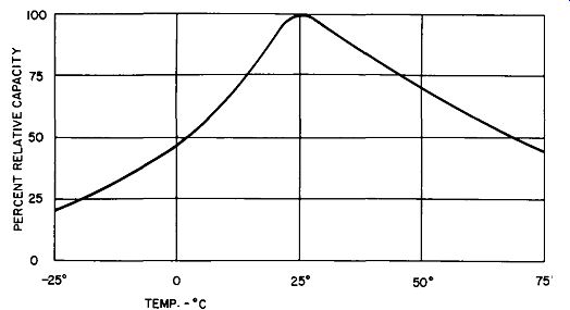
Fig. 3-14. Characteristic curves of general-purpose disc ceramic capacitors-temperature
versus capacity.
Temperature-compensating disc ceramics are designated by a number with a letter prefix. The system is actually fairly simple, once you become familiar with it. The prefix P means that above +25°C the capacitance will rise with the temperature (or a positive coefficient); N means the capacitance will drop (negative coefficient) ; and NPO signifies no change. The larger the number following the prefix, the greater the change. NPO types will of course have no number.
Thus, a designation of P100 means that for every degree centigrade that the temperature increases (between +25°C and +85°C), the capacitance will rise 100 parts per million.
An N750 rating produces a decrease of 750 parts per million per degree increase, whereas an N1400 produces almost twice that amount.
These capacitors are particularly useful in compensating for value changes which occur in other components when equipment temperature rises. Fig. 3-15 shows typical curves of performance.
Temperature-stable disc ceramics are merely a refinement of the temperature-compensating type. They have an extended temperature range and are rated from -60°C to +110°C, with a capacitance change of about ±7.5% from the stated value at +25°C. Both types are rated at 1,000 VDC.
Frequency-stable disc ceramics maintain a relatively fixed resonant frequency over a wide temperature range, unlike other types where temperature has a very marked effect on resonant frequency. Because they utilize materials with higher power factors in order to achieve the desired stability, frequency-stable discs are more susceptible to charge discharge cycle problems.
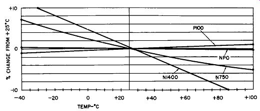
Fig. 3-15. Characteristic curves of temperature compensating disc ceramic
capacitors.
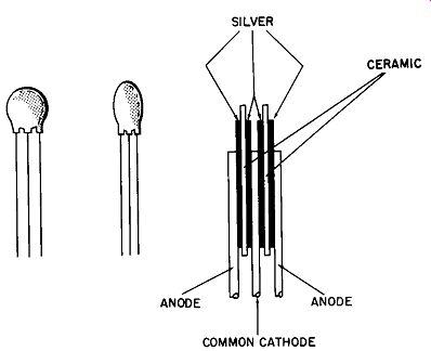
Fig. 3-16. Dual-disc ceramic capacitor construction.
Disc ceramics are normally used individually. However, a number of dual-section types are available. They are particularly useful where mutual coupling between capacitors would alter the circuit characteristics. Dual ceramics consist essentially of single units encapsulated back-to-back as in Fig. 3-16.
Tubular ceramic capacitors correspond in basic principle to the Leyden jar. They consist of a ceramic dielectric tube with silver plating deposited on both the inside and outside.
The basic construction of this type is shown in Fig. 3-17.
Leads may be either axial or radial, or a special arrangement as in a feedthrough unit.
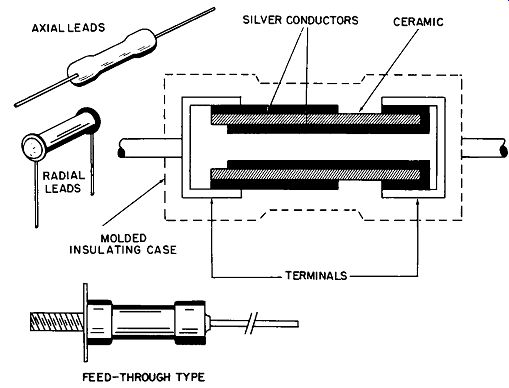
Fig. 3-17. Tubular ceramic capacitor construction.
Tubular ceramics have a poorer size-to-capacitance ratio and slightly more inductance per mfd than disc types. Because of this, their use has become rather restricted, except the feedthrough types. Furthermore, tubular types are more fragile than discs.
Because of their superior dielectric properties, ceramic capacitors are becoming more popular than the older mica types in trimmer applications. There are two common basic configurations. One configuration is essentially a concentric tubular unit, and the other is similar in principle to the variable air type.
The variable tubular (Fig. 3-18) consists of a silvered supporting tube with one plate on the inside. A movable ceramic tube, fired with silver on its inside, fits precisely within the first tube. As the inner tube is moved the effective area of the plates changes and varies the capacitance.
A typical adjustment range is from 1 to 8 mmf.
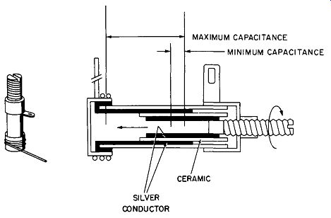
Fig. 3-18. Variable tubular ceramic capacitor construction.
The tubular variable ceramic is a precision type which produces very small changes in capacitance as the screw is rotated. However, the total capacitance is relatively small.
Another variable ceramic, quite popular as a trimmer, consists of two partially silvered, ground ceramic discs.
As the one disc is rotated, it presents more or less effective plate area to the fixed disc. This is very similar to the action of a variable air capacitor, as shown in Fig. 3-19. Its principal advantages are that a 180° rotation produces maximum capacitance change, and that it is available in larger values than the tubular type. Furthermore, temperature compensating types ranging from NPO through N750 are possible, with ratings of 1.5-7 mmf and 8-50 mmf. Side-by side dual-variable types are also available.
Ceramic capacitors of the so-called "door-knob" type are common in TV high-voltage applications. They are supplied in large molded cases with rings arranged to minimize high voltage flashover.
Another type of ceramic capacitor, intended primarily for universal replacement use, is actually a set of laminated units. Its leads are brought out in such a way that by soldering certain ones together, and cutting others off, a wide range of values can be obtained. The biggest advantage to the service technician is in not having to stock as many different ceramic types. There is some size and performance disadvantage, however.
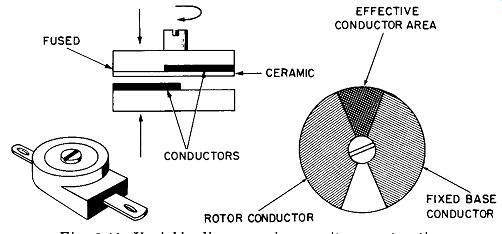
Fig. 3-19. Variable disc ceramic capacitor construction.
Ceramic capacitors, especially the disc type, are becoming ever more popular with equipment designers. But there are some important facts you should be aware of in working with these components. First, moisture can radically affect their performance. Even though manufacturers go to great lengths to insure moisture-resistant enclosures, there is still some possibility of infiltration.
All ceramics tend to be rather fragile. Avoid exerting more than a very slight pressure on leads during installation, because you may crack the base material or even dam age the capacitor internally. Also, be extremely careful while soldering, because excessive heat will ruin a capacitor.
ELECTROLYTIC CAPACITORS
Electrolytic capacitors provide more capacitance, for their size, than any other type. From the service technician's viewpoint, they are also the most confusing. They seem to defy all the rules applicable to capacitors-yet electrolytics are able to perform jobs no other type can. Fig. 3-20 shows only a few of the wide range of values and sizes that are available.
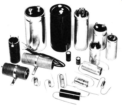
Fig. 3-20. Typical electrolytic capacitors.
Electrolytics all have one thing in common, however they are made differently from other capacitors. (See Fig. 3-21.) Instead of the usual plates separated by a dielectric, the electrolytic has an aluminum anode coated with a film of aluminum oxide. This outer covering is the dielectric, and a liquid electrolyte acts as the cathode. A second metallic conductor, usually of aluminum also, serves primarily as the connection to the liquid cathode, providing an external termination.
In actual practice, porous paper is wrapped around the anode and saturated with the electrolyte to eliminate the spillage problem.
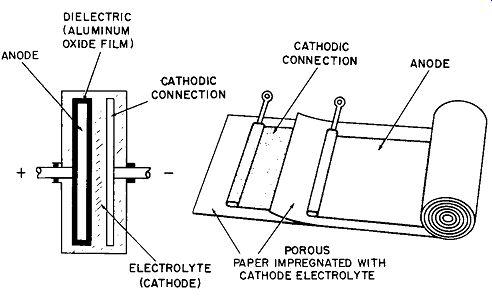
Fig. 3-21. Basic electrolytic capacitor construction.
The aluminum oxide film has a very high resistance to current in one direction and a very low resistance in the opposite direction. In other words, the film acts as a dielectric in the first instance and as a plate in the second. Because of this, electrolytics are polarized. If the designated polarity is not observed, the oxide film on the anode will break down and migrate to the cathodic connection, resulting in prompt failure of the capacitor.
Electrolytics are made in three basic styles. The polarized type is the one just described. Its aluminum oxide film is relatively thick, and its physical size is very small per unit of capacitance.
The semi-polarized type has a thin oxide film on the cathodic connection also, much thinner than on the anode. During polarity reversals of relatively low currents, this connection will act as an anode and offer minimum resistance to this small current flow.
The nonpolarized type is actually double-polarized-both plates being coated equally with oxide and therefore insensitive to polarity reversals. This type is commonly used in AC circuits such as for motor starting. The non-polar types are substantially larger per unit of capacitance than the polarized type. Fig. 3-22 shows the relative sizes and basic construction of the three types.
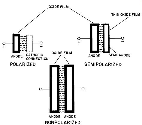
Fig. 3-22. Three types of electrolytic capacitors showing relative size for
same capacitance value.
The anodes in an electrolytic capacitor are more than simple flat aluminum foil. Prior to the formation of aluminum-oxide film, the anodes are deep-etched in an acid bath.
This etching process produces a roughened surface which vastly increases the effective area. Since capacitance is directly proportional to the effective anode area, etching results in a capacitor having more than ten times the capacity of a unit with a plain anode of the same physical size.
The "cathode" is also often treated similarly. Etching increases the contact area between the actual (liquid) cathode and the cathodic connection ("cathode"). Thus, current carrying capabilities are increased. An added advantage is that hum-producing oxide film is less likely to form where AC ripple currents are encountered in power-supply applications.
Electrolytics are supplied in aluminum or plastic cans.
All present types are of the "dry" arrangement--that is, most of the electrolyte is in the porous paper. On the other hand, the older "wet" type was filled with an electrolyte and the metal container served as the cathodic connection.
A vent in present-day capacitors keeps out external contaminants, but still allows pressure equalization at high temperatures.
The electrolyte is varied, depending on the voltage rating of the capacitor. Basically it consists of a solution of ammonium borate and boric acid, plus glycol to prevent freezing. It is wise to remember that the electrolyte is compounded for a specific operating voltage. This means that the electrolyte for 150 VDC is slightly different from one for 450 VDC. Therefore, it is unwise to consistently operate a 450-VDC unit at far below the rated voltage. Eventually the oxide film will become deformed and the total capacitance will deteriorate as a result.
Electrolytic capacitors have a characteristically higher leakage current than other types. This is due partially to their design and partially to impurities in the foil and electrolyte. Leakage current increases as the temperature rises; simultaneously, the voltage-breakdown resistance de creases. This is a sort of self-feeding situation where the more the leakage, the hotter the capacitor becomes, further increasing the leakage, and so on. Therefore, the operating temperatures of electrolytics must never be allowed to exceed their maximum limit.
==========

Table 3-1
Maximum allowable leakage current for electrolytic capacitors.
Rated Maximum WVDC leakage (ma)
25 .002C + 0.1 50 .004C + 0.1 150 .010C + 0.2 450 .02C + 0.3
C = capacitance in mfd
===========
The DC leakage of electrolytics should conform roughly to the values given in Table 3-1. These figures will serve as a guide to the maximum allowable leakage current after continuous application of the rated voltage for a minimum of 500 hours. Thus, a 100-mfd 150-WVDC capacitor should have a leakage current of not more than 1.2 ma after 500 hours of continuous operation.
The power factor losses of electrolytics tend to be higher than other types. But since the power factor of these units can be misleading, it is more common to describe the losses in terms of equivalent series resistance (esr). Manufacturers' data show the esr on each value produced. For example, the esr for an etched plate, 100-mfd 150-WVDC unit, is 2.5 ohms. This rating is given for a frequency of 120 cycles at 25°C.
Electrolytic capacitors are rated at 25°C, and the value is stated as a mean capacitance with a tolerance. The latter is determined by the individual manufacturer and will vary depending on voltage rating. A typical tolerance would be -10% to +50%, for a capacitor of over 351 volts. Tolerance can be very important to the service technician. Here it means that a 100-mfd capacitor actually can range from 90 to 150 mfd. In other words, if you are faced with the necessity of replacing a 125-mfd unit, it would be quite satisfactory to use a 100 mfd capacitor as long as operating temperatures are held well below maximum. The temperatures encountered in normal home entertainment equipment will usually not exceed this maximum.
Temperature has a very marked effect on the capacitance of electrolytics. At -55°C, an electrolytic has practically no capacitance, and its power factor will be as high as 50 % .
When equipment has been exposed to extremely low temperatures, all electrolytics will lose a significant percentage of their normal capacitance. The increased power factor may be sufficient to cause internal heating when power is applied. This, in turn, may or may not result in capacity recovery.
Electrolytic capacitors seem to have all sorts of idiosyncrasies. They will gradually deform (decrease in capacity) if allowed to remain idle. Extended periods of idleness can be harmful to electrolytics. A sudden surge of full rated voltage may then break down the deformed oxide film and permanently ruin the unit. In order to reform an electrolytic, you can use a capacitor checker, starting with a low (101/c of rated) voltage setting and increasing it up to the rated maximum over a period of about one minute. Or you can do the same thing with a 5-watt resistor of approximately 1000 ohms connected in series with a voltage source not exceeding and preferably below the capacitor rating.
When one considers that the list price of an average unit is about $2.50, it seems wasteful not to take proper precautions when installing a new one. This is especially true if the capacitor has been idle for a year or more.
If this procedure seems a waste of time, consider the extra expense of a customer callback. You will always hear of technicians who ignore this operation. They may have been lucky, just like those who say they don't believe in changing the oil in their car.
For a final note on electrolytics, a word of caution: Some electrolytics have a very high capacitance and are of such excellent quality they can hold a LETHAL charge. Always be careful when working in circuits containing high capacity.
TANTALUM CAPACITORS
Although unfamiliar to most electronic technicians, tantalum capacitors are finding more widespread usage. At present their use is pretty much confined to military equipment and very high-quality devices such as computers.
Tantalum electrolytics have the highest capacitance per size than any other present-day capacitor. This makes them especially attractive for miniature electronic equipment in spite of their higher cost. This high cost is due partially to the fact that tantalum is a relatively rare metal. In fact, its name is derived from "tantalize" because it is so difficult to isolate and process. On the credit side, it is highly resistant to corrosion and has a high melting temperature.
The same principles that apply to aluminum electrolytics apply to tantalums. They are available in both polarized and nonpolarized foil form, as well as a unique configuration which utilizes a sintered anode.
Fig. 3-23 shows some representative tantalum capacitors. They range in size from a grain of rice, up to a normal metal-can electrolytic.
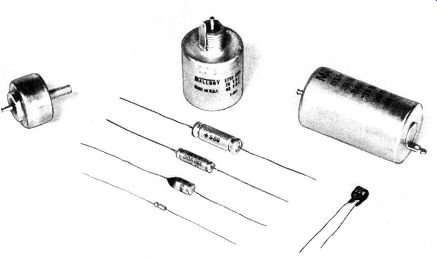
Fig. 3-23. Tantalum capacitors.
In addition to their small size per unit of capacity, tantalums can be operated at temperatures from -80°C. to +200°C. Furthermore, their capacity is significantly less affected by temperature than aluminum types. Their stability is excellent, and they can be stored almost indefinitely.
This fact alone has led to their adoption by public utilities because of the freedom from reforming them periodically while in storage. Operating life is equally long if normal precautions are observed.
Tantalum capacitors range in value from 0.25 to 2,200 mfd. Voltages range from 3 WVDC up to 640 WVDC. The foil types are normally furnished in axial lead styles, and may be either polarized or nonpolarized. The sintered anode types are furnished in a wide range of styles. The electrolyte may be either "wet" or "solid."
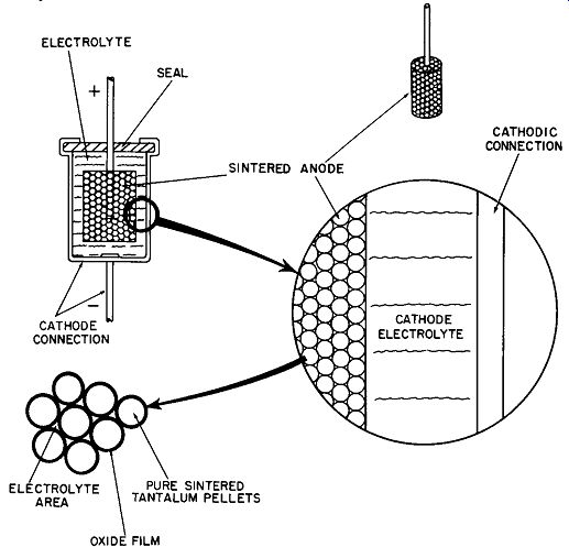
Fig. 3-24. Basic sintered-anode tantalum capacitor construction.
Tantalum foil capacitors are constructed in almost the same manner as the aluminum electrolytic type. The tantalum electrolyte may be sulphuric acid or lithium chloride, depending on the characteristics desired.
Fig. 3-24 illustrates the basic construction of the sintered anode type of tantalum capacitor. Pure tantalum is produced in minute pellet form. It is then pressed, under very high pressure, into a cylindrical shape onto a supporting and conducting tantalum wire lead. This cylinder is then fired in a furnace to fuse the areas of contact. It is then electrochemically treated to form a tantalum oxide coating over the entire sponge-like surface. The acid electrolyte is then forced into the cylinder under high vacuum and the cylinder is assembled into the case, which can also serve as the cathodic connection. More electrolyte is introduced and the assembly is sealed.
This type of construction has several advantages. The actual surface area of the sponge-like cylinder is very large in proportion to its volume. The electrolyte intimately contacts every part of the oxide film, which in turn contacts every surface of the tiny tantalum pellets. Resistance to physical shock is excellent because the anode is a single homogeneous unit.
Actual manufacturing practices are much more refined than the drawing in Fig. 3-24 would seem to indicate. Double cases and true glass-to-metal hermetic seals are often employed.
The construction just explained is called the "wet-slug" process. The electrolyte is a liquid, and the sealing problems are concerned primarily with preventing the escape of this highly corrosive electrolyte. Operating temperatures range from -55°C to +200°C. Another type of construction utilizes a solid electrolyte.
Its principal advantage is improved performance at very low temperatures. Depending on case structure, these capacitors may be operated at temperatures ranging from -80 C to +125°C. The cylindrical anode is prepared in exactly the same manner as the wet type, up until the introduction of the electrolyte. At this point, a solid electrolytic material is vacuum-impregnated into the anode and baked to assure complete dryness and adhesion. Appearance externally is similar, but the performance is different. Another form of this capacitor uses a flat anode with an epoxy encapsulation and parallel leads similar in appearance to disc ceramic types. It is useful in printed-circuit applications. The sealing problems of solid electrolyte types are more concerned with preventing the entrance of outside contaminants and are thus less severe than for the wet type.
Tantalum capacitors are relative newcomers to the capacitor field, and as such are in a constant state of improvement. As these types gain wider acceptance, increased production will probably reduce their price and they will appear in more consumer applications.
SPECIALIZED CAPACITORS
There are a number of specialized capacitors. Among them are the glass and the vitreous enamel types, used primarily as high-grade replacements for mica and ceramic units where operating conditions require a better type of capacitor.
Glass dielectric capacitors are made of alternate layers of glass ribbon and a conductive metal. The entire assembly is fused into a solid block under high temperature and pressure. This type offers the best protection from moisture in filtration because the outer case is the dielectric. Hence, there are no joints to fail.
Vitreous enamel types are constructed in a similar manner, except the glazing material is substituted for the glass.
If the plates and dielectric have a different coefficient of expansion, extreme temperature changes may cause the two to separate or the dielectric to crack. Both types are able to withstand acceleration of several G's--yet may be easily damaged by a mild physical blow.
Performance roughly parallels that of mica types, but lacks the temperature-compensating characteristics of the ceramic types. They are used primarily where high humidity might cause failure of other types.