AMAZON multi-meters discounts AMAZON oscilloscope discounts
Selecting the proper capacitor for a specific application is a problem which confronts the average electronics man at some time or other. In the case of equipment repair, re placement of the defective unit with an exact duplicate is a simple matter. As often happens, however, an exact re placement may not be available, so a suitable substitute must be made. Others may want to design their own equipment and therefore will need information about the correct units to employ.
OPERATING CHARACTERISTICS
The principal use of a capacitor, from a theoretical stand point, is for simple energy storage. In any capacitive circuit some resistance will always be present, offering an opposition to the charge and discharge of the capacitor. Therefore, the RC time constant becomes important and must be considered in selecting a capacitor for a particular circuit.
Two capacitors of equal value but different internal resistance will have different charge-discharge time cycles the unit with the higher resistance taking longer to charge or discharge. This can be expressed by the formula: t = RC, where t is the time in seconds, R the resistance in ohms and C the capacitance in farads. Since time is a factor in any AC voltage, the RC time constant is directly affected by the voltage frequency. Hence, a capacitor might be usable in a low-frequency circuit, but be unsuitable at higher-frequencies. Size, weight, and cost often govern the selection of a particular unit. Therefore, you might run into a situation where a tantalum capacitor would have been the perfect answer, and yet find an ordinary aluminum electrolytic has been used. The reason here is cost. On the other hand, an oil-filled paper capacitor might be electrically indicated, but an electrolytic used instead. Bulk and weight considerations led the designer to the selection here.
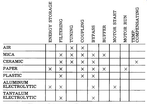
Fig. 4-1. Primary applications of capacitors.
Yet, despite all these rather confusing considerations, you will find that certain types of capacitors are nearly always used for particular applications. The reason is simple-most engineers are faced with the same problems, consult the same books, and arrive at similar answers. The chart in Fig. 4-1 shows the primary applications of the most common types of capacitors. Glancing over this chart, you will note that filtering can be done by almost any type-the over-all requirements of a particular circuit determine the final selection here.
The preceding paragraphs may have led to a certain amount of confusion in your mind. To partially dispel this, let us now examine particular applications and, in at least a general way, find out which capacitors are most suitable.
ENERGY STORAGE
The simplest capacitor applications is for energy storage. Here the only problem is storing the required quantity of electrons to meet a specific need. Examples of such applications are welding and electronic photoflash. Primary considerations center on the total energy required, space avail able, charge-discharge time, and cost.
We will start with the energy requirement. Assume we are concerned with an electronic-flash application calling for a power of 100 watt-seconds. Our power supply is 450 VDC. What value of capacity will be required? The following formula will enable us to make an approximate choice.
where,
W=-2 100 = C x 450~ 2
200 = C x 202,500 200
C = 202,500
C = .000987 farads or 987 mfd.
W is the amount of work in watt-seconds,
C is the capacitance in farads,
V is the DC voltage.
The fact that the power supply is rated at 450 VDC and the capacity is large means we should consider using an electrolytic capacitor. We might select a single 1,000 mfd 450 VDC unit, or two 500-mfd capacitors in parallel. The latter would be the more practical solution, since 1,000 mfd units are scarce and relatively expensive.
Suppose, however, that our power supply was 2,500 VDC. Obviously, we cannot use an electrolytic capacitor with such a high potential. The only other type available is an oil-filled paper dielectric. Using the formula as before, we find a value of approximately 32 mfd is indicated. The unit is much larger and heavier, but is comparable in cost to the electrolytic.
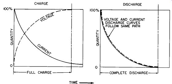
Fig. 4-2. Charge-discharge cycle of a capacitor.
Another consideration in energy storage is the charge discharge cycle. If either cycle is fairly long, almost any capacitor will do. The shorter either cycle becomes, however, the more important internal resistance becomes.
You will recall that we considered this cycle in Section 2.
Typical curves are shown in Fig. 4-2. The length of time a capacitor takes to reach full charge is a function of the charging force, and the internal capacitor and external circuit resistances. Therefore, a capacitor with a higher internal resistance will have longer charge and discharge cycles.
If the circuit requires very short cycles, we must select suitable capacitors. One method is on the basis of work required. Here we might use much larger units than are needed, in effect shortening the time cycle. This would result in a further advantage-the internal heating of anotherwise unacceptable unit would be reduced to a safe level. Cost would be higher, however.
From the service technician's standpoint, capacitor replacement is much more important than original selection. Also, it is his responsibility to make certain the replacement matches the characteristics of the original equipment.
FILTERING
Capacitors in a rectifier circuit are used principally to smooth out DC current pulses derived from an AC source. In this sense they function as storers of energy. The degree of smoothness required and the inherent circuit characteristics are used as the basis for capacitor selection.
Below 450 volts and/or 1 khz, electrolytics are an excellent choice if current requirements are fairly high. Higher voltages and/or frequencies will require paper or plastic types, and still higher will require micas or ceramics.
As is true for pure energy storage, the RC time constant of filter capacitors is of prime consideration. It must match the requirement of the over-all circuit, particularly if you are replacing a mica with a ceramic type. (Naturally, all other characteristics must match in this instance, too.) The job of a filter capacitor is to remove all unwanted frequencies. Take an antenna filter, for example. One can select a series of capacitors and coils which will eliminate virtually all but the important range of signals needed.
Air dielectric types are the most common here because of the high frequencies and very low currents. An added feature is that tuning to other frequencies is easier.
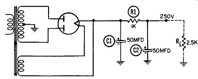
Fig. 4-3. Circuit of a typical power supply illustrating filtering action
of capacitors.
Another use of filtering capacitors is in power-supply circuits, as shown in Fig. 4-3. Here the essential function is to filter out the unwanted AC variations in order to produce an essentially ripple-free DC voltage. In this circuit the input to the filter capacitors is a pulsating DC voltage with a frequency of 120 hz. At the first impulse, capacitor C1 starts charging through the rather low resistance of the transformer winding and the conducting rectifier tube. Be cause of its large capacitance, C1 takes several cycles to become completely charged, however. During this period C2 is also attempting to charge, but through a slightly higher resistance since R1 is in series with it. After the first few cycles both capacitors will be charged to the supply voltage. With no load, (R1, disconnected) the voltage at the output terminals will remain constant since there is no external discharge path for the two capacitors. If the load is now connected a path will be provided, but the RC time constant of the circuit will be so long that the filters will have only a very short time (4000 microseconds at 120 hz) to discharge. Even with such a short discharge time, the output voltage will drop slightly, but will rise on the next charge cycle. This produces a slight ripple with a resultant hum in the output. As long as the ripple is low in amplitude, however, the hum will not be bothersome.
BYPASSING
It is often desirable, and sometimes necessary, to eliminate a particular frequency by bypassing it to ground.
Where more than one frequency must be passed and others bypassed, other components are needed besides the capacitor. Such a situation is shown in Fig. 4-4.
Capacitor C7 and variable resistor R2 function together as a tone control in a typical radio receiver. Note that the two are connected in series from the plate of the AF amplifier to ground. Audio frequencies are present at the plate and appear across R11 for further amplification in the output stage.
R2 and C7 form an RC circuit, the impedance of which is determined by the value of the two components. With R2 adjusted for maximum resistance, a total of 1 meg will be placed in series with .005 mfd. At 1,000 hz the total impedance will be approximately 1 meg, and even at 10,000 hz it will be nearly the same. This means that regardless of frequency, any audio signal at the plate will be relatively unaffected by the tone-control network.
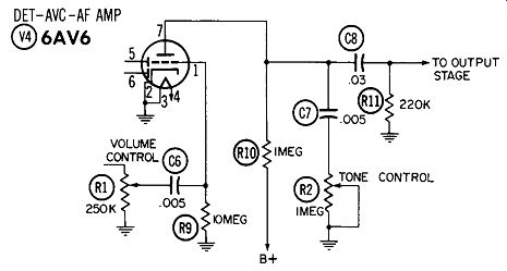
Fig. 4-4. Circuit illustrating frequency bypassing action of an RC combination.
Reducing the resistance to zero will leave only the capacitive reactance. At 1,000 hz we find that it is nearly 32 K, whereas at 10,000 hz it is only 3.2 K. The higher frequencies will therefore be greatly reduced in amplitude (bypassed to ground). On the other hand, the impedance at the lower frequencies is much greater, providing ten times as much signal amplitude.
COUPLING OR BLOCKING
Besides their pure energy-storage capabilities and charge discharge cycles (RC time constant), capacitors possess a number of other characteristics which can be either a detriment or asset, depending on the intended use. In other words, some of the very things that might otherwise be considered faults make it possible for the capacitor to do a job no other component or group of components could do as well.
Take a blocking or coupling capacitor, for example. Here the idea is to block any DC current while allowing an AC current to pass. What we are actually doing here is using a capacitor which charges to the DC level, but simply doesn't have a fast enough reaction (RC time constant) to charge at the AC rate.
Most blocking capacitors in TV or radio sets are paper or plastic film. Cost is paramount, and the DC voltage to be blocked is within the range of these types. A typical blocking circuit is shown in Fig. 4-5.
Capacitor C keeps the DC voltage in the plate circuit from appearing on the grid of V2. In other words, C is "blocking" this voltage. At the same time we want any AC signal voltage at the plate of V1 to be transferred to the grid of V2.
This can be done through the combined action of C and Rg, Hence, the capacitor has effectively "coupled" the two stages, as far as the signal is concerned.
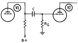
Fig. 4-5. Use of a capacitor for blocking and coupling.
Here again the time constant formed by the two units must be considered. The RC time must be sufficiently long to prevent the capacitor from appreciably charging and discharging at any audio frequency we might want coupled to the grid of V2. This will cause most of the signal voltage to appear across R". If made too long, however, a positive voltage may be built up on the grid, causing distortion and possible tube failure. A compromise must therefore be made.
The capacitor is kept near or below .05 mfd, and resistor values are selected to give a time constant of about 5000 microseconds.
DIVIDING
Rather than eliminating certain frequencies, it is often more desirable to divide them. The circuit in Fig. 4-6 is an example of this situation. Here the capacitors are chosen to pass one range of signals while blocking all others.
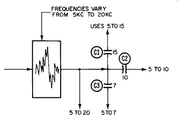
Fig. 4-6. Using capacitors as frequency dividers.

Fig. 4-7. Sync-separator circuit used in one General Electric television model.
Note that C1 will pass all signals below 15 khz, C2 passes all those below 10 khz, and C3 all those below 7 khz. Thus the total 5-20 khz signal can be used for one purpose, the 5-15 khz for another, and so on. The signals that pass are only slightly affected by the capacitors and hence are usable for their intended purposes.
A practical demonstration of this principle is illustrated in Fig. 4-7. The same sync separator is most descriptive of the circuit action, as we shall see.
Both horizontal- and vertical-sync pulses are present at the plate of V4B. Their frequencies differ widely-15,750 hz for the horizontal but only 30 hz for the vertical pulses. The RC network ( dotted lines) offers a higher impedance path to the 15,750 hz than does capacitor C46. Therefore, the larger portion of the horizontal-sync signal will pass through C46 to the horizontal AFC circuit, and only a negligible amount will enter the RC network.
To the low-frequency (30- hz) vertical pulses, the reverse is true-the network offers a much lower impedance path than does C46, so most of the vertical-sync pulses will pass through the RC network and into the vertical-oscillator circuit.
Here again, the choice of capacitor is determined by the characteristics desired and by the current and frequency requirements.
BUFFER
Buffers utilize the energy-absorption characteristic of a capacitor. They are commonly associated with vibrators or choppers, their purpose here being to avoid contact arcing; the same problem exists with switches and relays.
As current flows through the closed contacts of a relay or switch it reaches some maximum value and remains there. When the contacts are opened, a spark will occur; and if it is sufficiently intense or occurs repeatedly, it can damage the contact material. If the abruptly interrupted current has been flowing through an inductive circuit (a relay coil, transformer winding, etc.), the collapsing magnetic field will generate a high voltage in the inductance, and this high voltage will maintain and even intensify the arc.
Arcing can be minimized by placing a capacitor in parallel with the contacts. The excess electrons that formerly caused the arc are now used to charge the capacitor and thereby prevent damage to the points. As the contacts close, the capacitor discharges, making it ready for the next voltage surge. Fig. 4-8 illustrates a method of contact protection.
The most common type of buffer used is the paper capacitor with a value chosen that will be a function of circuit requirements. In some cases, a plastic film unit might be suit-able, but the superior surge voltage ratings of the paper type make it more desirable.
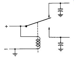
Fig. 4-8. Using capacitors to protect relay contacts.
TUNING
There are other applications where the choice of a particular capacitor type is so clear that very little discussion is required. Such is the case in tuning. The air dielectric type is predominant here, because RF frequencies are involved, stability is very important, and long mechanical life is desired. Ceramic or mica trimmer capacitors may be used to complement the air unit.
Not all tuning devices are capacitors, however; a great many are inductive units. They will not be discussed in this guide, except to note their existence and to point out that they cannot be replaced directly by capacitive devices.
AC MOTOR STARTING AND RUNNING
An extremely important use for capacitors has nothing to do with radio or TV. But whether the electronic technician ever makes use of this information or not, it is of some value, if only from a personal standpoint.
For many household appliances it is desirable to have fractional horsepower motors capable of a high starting torque. Repulsion-induction motors will provide this torque, but are relatively expensive to construct. A less expensive solution is the capacitor-start motor. It has a normal set of heavy windings for running and a lighter set for starting.
A centrifugal switch connects a capacitor to the start winding to shift the phase, resulting in a high torque being developed. As soon as running speed is reached, the switch cuts the capacitor and start-winding out of the circuit, and the motor operates as a single-phase unit.
Because of the high capacitances required, aluminum electrolytics are commonly used in capacitor-start motors. The capacitor may be in a housing on the exterior of the motor frame, placed inside the frame, or fitted inside the bell of the motor frame. The latter two have been largely supplanted in recent years by the more economical and more satisfactory exterior mount.
Major causes of capacitor failure include aging and excessive start cycles, voltage, and temperature. Another major cause of failure is mechanical-if the centrifugal switch contacts fail to open, the capacitor will quickly fail. On the other hand, if they open too soon, running speed will not be reached and the start cycle will occur repeatedly until the capacitor eventually fails.
Before replacing a motor start capacitor, always check the mechanical condition of the motor for bad bearings, dirty switch, etc., first. It is always best to mount the replacement on the motor exterior even though the original was not. In this way, the capacitor will run cooler and last longer.
Motor run capacitors are used in conjunction with a low starting-torque motor like the one in a fan. Here, quietness of operation is the principal advantage, with small size a close second. Motor run capacitors are always oil-paper types. Failures are traceable primarily to excessive voltage and/or temperature.
A third type of motor is the capacitor start and run. It is used in large fans and in air conditioners, where both high starting torque and quiet operation are required. This motor is merely a combination of the two mentioned previously.