AMAZON multi-meters discounts AMAZON oscilloscope discounts
How will you know a capacitor is bad? Or for that matter, how will you know it is good? Beyond the fact that a capacitor lead is completely burned off or broken in two, there are other ways a capacitor can become defective. It may be shorted or completely open (have no capacitance at all). Capacity may have drifted from the desired value, or the internal resistance may be too low or too high. DC leakage may also be much too high. Most of these defects can be detected fairly easily.
A few tests can be performed with the unit still in the circuit; others require that at least one lead be unsoldered.
TESTING WITH THE VOM OR VTVM
In complex circuitry, particularly where printed boards and/or miniaturized components are used, it is best to make as many in-circuit tests as possible. There's no sense un soldering or removing components from the circuit until other tests lead you to believe that such action is necessary.
Take, for example, the coupling capacitor C8, in Fig. 6-1.
If a voltage measurement indicates that a potential of 25 volts is present at the grid of V2, it is reasonable to assume that the capacitor could be leaky. But before carrying this assumption further, why not obtain additional proof? After all, a shorted V2 could be responsible for the positive grid voltage. Unless there is reason not to do so, the tube can be removed from the socket and the grid voltage measured again. If the same condition is noted, and there seems to be no other contributing factor, it's time to disconnect the grid end of the capacitor from the circuit.

Fig. 6-1. Audio amplifier circuit.
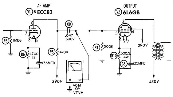
Fig. 6-2. Use of VOM or VTVM for testing capacitor leakage.
As shown in Fig. 6-2, there are two methods of testing for capacitor leakage, using nothing more than a VOM or VTVM. With the set turned on, and no signal coming through, you need only measure voltage or current by connecting the appropriate meter between the open end of the capacitor and ground. Normal readings, depending on capacitor type and value, should not exceed two or three volts, or 5 to 10 ma. A word of caution in making these voltage and current measurements: a badly shorted capacitor will permit high currents to flow through the ground return path provided by the meter, so be sure to start out on a scale high enough to prevent damage to the meter.
There is one other simple, although not entirely conclusive, in-circuit test you can make for a shorted capacitor.
If a capacitor is badly shorted, you can usually discover the defect with the use of an ohmmeter. Before making this test, make sure no voltages are present in the equipment otherwise, damage to the meter will result.
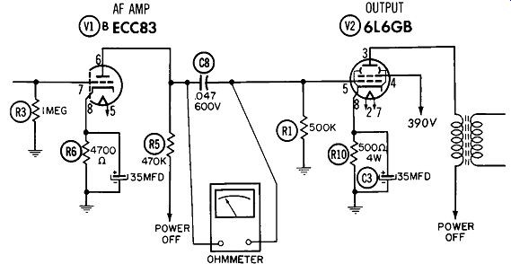
Fig. 6-3. Use of ohmmeter to detect shorted capacitor.
As shown in Fig. 6-3, merely connect the ohmmeter across the suspected unit, using the scale that provides a usable reading. In order for the test to have any validity, you must compute the resistance value for existing parallel paths.
This computed value is approximately what the meter should read. If the measured resistance is lower, either your computation of the parallel resistance path is in error, or the capacitor is leaky. Disconnecting one end of the capacitor from the circuit and making a resistance measurement only across the capacitor should prove which is true. A word of warning when testing low-voltage capacitors commonly used in transistor radios; make sure the meter voltage does not exceed the rating of the capacitor under test. There are a great number of 22½-volt meters in use, and they can ruin an otherwise good 3-volt capacitor.
The voltmeter or milliammeter tests provide a more positive means of checking for capacitor leakage than the ohm meter measurement because normal circuit voltages are applied to the unit under test. If a capacitor is breaking down intermittently, it is more likely to do so when B+ voltages are applied; the ohmmeter measurement does not take this factor into account.
Checking for open capacitors is a fairly simple task, also.
But again, by making in-circuit tests first, you can save much time and trouble. One of the best tests involves the use of an oscilloscope or AC voltmeter to check for the presence of signal. Of course, you must know what to expect in the way of waveform or voltage indications. For instance,
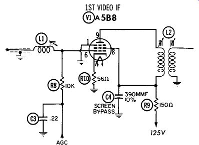
Fig. 6-4. TV video-IF stage showing screen bypass capacitor.
you would expect a coupling capacitor such as the one in Fig. 6-1 to pass practically all of the signal available from the plate of V1 to the grid of V2. On the other hand, in the circuit of Fig. 6-4, you would expect to find very little AC signal present at the screen grid. Excessive signal at this point would indicate that the screen bypass unit (C4) was not doing its job. As with the shorts tests, disconnecting one end of the capacitor from the circuit, and making the same tests again, should provide sufficient information for you to decide whether or not the capacitor is defective.
Some indication of an open capacitor can often be obtained with the use of an ohmmeter. When disconnected from the circuit, and fully discharged, connecting an ohm meter across the unit will cause it to charge. As was pointed out in Section 2, the time it takes for a capacitor to charge is governed by the value of capacitance and the amount of series resistance in the circuit. The ohmmeter itself has several thousand ohms of resistance ( depending on the scale used) ; thus, if the capacitor is of fairly large value-say, .01 mfd or more-the time constant will be such that it can be distinctly noticeable from the change in the ohmmeter reading. On the 100K scale, for example, the initial reading for a normal capacitor may be in the neighborhood of 500K. That is, the pointer may swing over as far as mid-scale, and then swing back--rapidly at first, and then gradually more slowly-until the reading is near infinity. If you could accurately plot the resistance readings on a time scale, you would find they duplicate the capacitor charging curves discussed in Section 2.
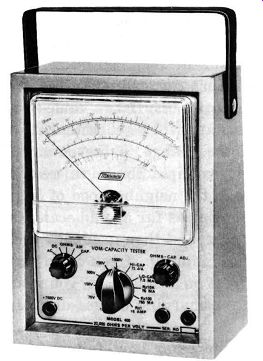
Fig. 6-5. The VOM-capacity checker manufactured by the Mercury Electronics
Corp.
As you have undoubtedly surmised by now, failure of the ohmmeter to react as described is a pretty good indication that the capacitor is open. Remember, however, that capacitor value must be sufficient to provide a measurable charging period. A value of 330 mmf might not produce more than a slight flicker of the ohmmeter needle. Incidentally, the phenomenon known as dielectric absorption, described in Section 2, is most likely to be encountered when using the highest scale of the ohmmeter ( usually 1 meg or 10 meg). Therefore, to obtain a valid test, switch to the next lowest scale. (Dielectric absorption will not generally be encountered in mica, ceramic, or electrolytic capacitors.) As far as capacitor value is concerned, a VOM equipped with an AC scale can be used to obtain an approximate reading. Specific instructions for this measurement are usually included in the operating manual for the instrument. Some instrument scales are calibrated directly in microfarads, making measurement of capacitance values a relatively simple matter. Fig. 6-5 illustrates such a unit.
Using the ordinary VOM as a capacitor checker has its limitations. In the first place, it really wasn't designed for the job and, for this reason, is primarily useful in providing only preliminary information. When it comes to accurate measurements of value, leakage, power factor, etc., a regular capacitor checker is called for. There are two general types--the in-circuit and the out-of-circuit-and each has its particular applications and limitations.
IN-CIRCUIT CAPACITOR CHECKERS
The in-circuit capacitor checker will tell you at a glance whether or not a capacitor is shorted or open. But it cannot tell you the exact value of a particular capacitor. It is in essence an all-or-nothing device. Most of the time, this will do-as far as you're concerned, either a capacitor is working or it is not. Fig. 6-6 shows an in-circuit checker.
OUT-OF-CIRCUIT CAPACITOR CHECKERS
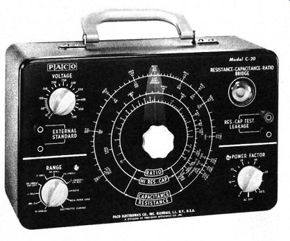
Fig. 6-7. Paco out-of-circuit capacitor checker. This type unit is able to
measure capacitor values, leakage current, power factor and resistance.
There are circuits where the value of the capacitor can be especially critical. For instance, in a divider network a slight shift in capacitance can seriously affect performance.
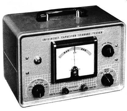
Fig. 6-6. Simpson in-circuit capacitor checker.
If trouble is indicated here, the capacitor must be removed from the circuit (or, at least one lead unsoldered) before it can be accurately checked. All out-of-circuit capacitor checkers, such as the one shown in Fig. 6-7, use some modification of a balanced-bridge circuit. The principle involved is simple-a known capacitance is balanced against the unknown by coupling an appropriate variable resistance to a calibrated dial. When the needle shows that the circuit is balanced, the capacitance value can be read directly from the dial. Other checkers may use variations of this circuit, but they accomplish the same results. A basic bridge circuit, used in many out-of-circuit testers, is shown in Fig. 6-8.
The leakage resistance of capacitors varies from very high in micas and ceramics, to very low in electrolytics. Checking for a change in this characteristic can be performed only with an out-of-circuit tester or an appropriate bridge. Since values range up to 20,000 megohms, the correct test setup is required to insure accuracy.
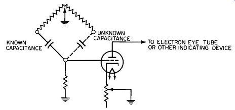
Fig. 6-8. Bridge circuit used to measure value of unknown capacitor.
Excessive DC leakage is a common problem with capacitors. It is usually expressed in terms of the internal resistance, because leakage is low whenever resistance is high.
In electrolytics the leakage is high enough that it can be compared directly. The test for DC or AC leakage must be performed with the capacitor out of the circuit. Manufacturers of both test equipment and capacitors supply charts indicating the correct amount for each type and value.
These should be used in place of any rule-of-thumb, and even then judgment will be necessary. It is essential to keep the capacitor at the temperature specified (usually +25°C) when checking for DC leakage; otherwise, you will obtain an inaccurate reading. AC leakage is expressed as so many milliamps at a particular frequency ( usually 120 cycles per second) and temperature (such as +85°C). Out-of-circuit testers are also useful for measuring the power factors of electrolytics. A bridge similar to the one in Fig. 6-8 is used. Here again, the test must be performed at rated temperatures only.
Another method of checking capacitance, described in Section 2, is to use the time constant. It is generally restricted to elaborate laboratory tests, mainly because a great deal of expensive equipment is involved.
COLOR CODES AND SYMBOLS
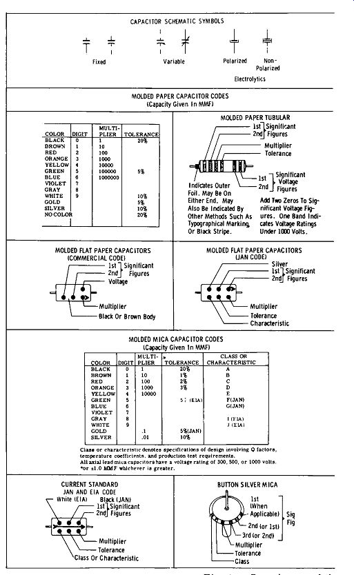
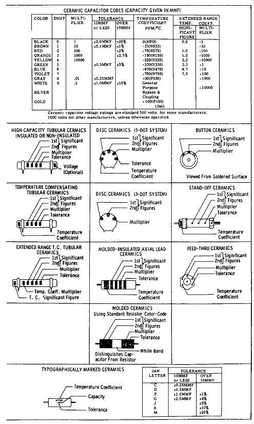
Fig. 6-9. Capacitor symbols and color codes.
A system of color coding to indicate capacitor values has been established and adopted by all major manufacturers of capacitors. Without such a system, confusion would result because of the myriad types of capacitors prevailing. These color codes are given in Fig. 6-9. Also included are the standard capacitor symbols appearing in schematic diagrams.