AMAZON multi-meters discounts AMAZON oscilloscope discounts
There are certain precautions you should observe before replacing a capacitor. The mere fact that it has the correct value and voltage rating does not guarantee successful results.
Suppose you are called on to repair a defective TV and find that two mica capacitors have failed. Unfortunately you have no exact replacement micas with you, but you do have ceramics. Can they be used instead? The answer is a qualified yes-you can almost always replace a mica with a ceramic of equivalent value. One thing to watch, however, is tolerance.
TOLERANCE
Capacitor tolerance is expressed in percent. Let's take the case of a ±10 % unit rated at 10 mmf. This means the manufacturer guarantees this particular capacitor will have a value of no less than 9 nor more than 11 mmf. But remember, he only guarantees this at the rated voltage and at 25° C (77°F). If the temperature is higher, the capacity will also be higher, and vice versa. This is true in all types except ceramics. The capacity-temperature characteristic of ceramics doesn't follow the rules for the other types-it's engineered into the specific dielectric used. You'll have to make certain these characteristics fit the job at hand. (You'll find much of the information you need in Section 3.) Before we leave tolerance, let's look at the one for a typical electrolytic. A tolerance of -10 % to +50 % means that a 100-mfd unit will have an actual capacity between 90 and 150 mfd. In other words, you would have to measure the capacitor to find its exact value. So remember-don't use ordinary electrolytics where capacity values are critical.
Tolerance is a measure of the over-all quality of a capacitor. It is obviously more expensive to manufacture a capacitor with a very close tolerance than with a very wide one.
The most practical method of accomplishing this, from the manufacturer's standpoint, is to build a group of units to a certain specification that should result in a certain value, and then test and label them for their specific value. As the voltage rating of an electrolytic increases, the capacity tolerance becomes less. A typical range would show capacitors rated at 1 to 50 VDC and having a tolerance of -10% to +250 %, while above 350 VDC the tolerance would be reduced to -10 % to +50%. Data on specific values are avail able from every capacitor manufacturer, and most of the time from your electronic parts distributor.
Ceramic capacitors are rated either in percent or in guaranteed minimum value (GMV). The percentage was explained earlier. GMV is simply the manufacturer's guarantee that the unit will have no less capacity than is stated. (Remember, this is at 25° C.)
TEMPERATURE
Let's return to the problem of substituting ceramics for micas. In addition to being careful about the tolerance, you will have to make certain the ceramic has the same electrical characteristics. In other words, you certainly wouldn't want to use a negative temperature-compensating type if it would upset the circuit. The safest thing to do would be to use an NPO type; it has a flat temperature curve.
Let's look at the other side of the coin for a moment. Sup pose the capacitor that has gone bad is a ceramic, and all you have are micas. If the bad ceramic is one of the general purpose type, go right ahead and put in the mica, because the circuit requirements are probably not too critical. But if the ceramic is one of the temperature-compensating types, you're in trouble-a mica won't do here. Its temperature versus capacitance characteristic just doesn't match that of the temperature-compensating ceramic.
TYPE CONSIDERATION
Here's another problem. Can a paper capacitor be replaced with one of an equivalent rating in a Mylar type? Yes, with one exception-paper types generally make better vibrator buffers than do Mylars. Paper types have superior surge current characteristics and generally a much higher corona starting voltage. However, this does not mean that paper capacitors are superior to Mylar types. Quite the contrary Mylars are smaller and have other operating characteristics (such as humidity protection) that make them superior to paper capacitors for most applications. As a general rule you can always replace a paper type with an equivalent Mylar, but be careful when trying to use a paper for a Mylar. The big problem will probably be lack of space, because Mylar capacitors as a rule are smaller.
Many inexpensive radios, and even some television receivers, use wax or paraffin-filled paper capacitors. They are more subject to moisture infiltration than the molded case types. For this reason, the latter should be used when replacement is required. As a matter of fact, if you run into one or more bad paraffin-filled capacitors in a circuit, it's usually a good idea to check the rest of them while you're at it.
Getting back to the replacement of micas with ceramics and vice versa, you may run into a situation where a tubular ceramic needs replacement. There is no problem here--you can nearly always replace a tubular ceramic with an equivalent disc type. As a rule, the small difference in inductance will have no effect. However, this is not true if the tubular ceramic happens to be a feedthrough type--the presence of a feedthrough ceramic practically guarantees that an inductance problem exists. The only thing to do here is use an exact replacement.
A similar situation occurs with trimmer capacitors-if an air type, replace with another air type. If the trimmer is a mica, you can consider a ceramic, provided their over-all characteristics match. But be careful about switching a mica for a ceramic trimmer-the temperature characteristics of the two may differ radically.
ELECTROLYTIC SUBSTITUTION
Can you replace an electrolytic with an equivalent paper type? How about vice versa? If the value of the electrolytic is low enough, you might be able to find a paper type that would fit the available space, although it's highly unlikely.
Remember, the electrolytic was no doubt chosen in the first place because of its smaller size. Also, it may have some peculiar electrical characteristic. Replacing it with a paper unit-even of the same value-could be a serious error.
The reverse is even more true. Except in the case of pure energy storage (DC), a paper type cannot be replaced with an electrolytic, even with one of equivalent value. Paper types were chosen originally because of their superior voltage characteristics, or because of polarity-reversal considerations. Remember, polarity is vitally important in an electrolytic capacitor. Even a momentary reversal could ruin one. Also, electrolytics do not have as close a tolerance as paper types.
VOLTAGE RATING
Service technicians run into all sorts of problems in a day's work. Take this one, for example. A .02-mfd 200 WVDC paper capacitor has shorted and there is no exact replacement anywhere in the shop. What would you do? You could use a 400 or even 2600 WVDC unit and no one would ever know the difference. Even a 1,000-volt unit might be all right, although it will be slightly larger and cost a bit more. Then, too, the electrical characteristics will start to change, because the voltage rating of a capacitor is deter mined by the thickness of its dielectric. Therefore, in order to gain the same capacitance, the unit must have a larger plate area. This in turn may change the internal resistance.
If the circuit requirements are not too critical, a 1,000-volt unit may be satisfactory. On the other hand, it may intro duce other problems.
As a rule, it is safe to substitute a capacitor of a higher voltage rating. But don't try to go the other way--if a circuit requires a 600 WVDC capacitor and you use 400, you can expect more than your share of trouble.
PARALLEL CAPACITORS
Another fairly simple problem is one where a certain capacitor is called for, but only smaller values are available.
For example, suppose you need an 80 mfd @ 300 VDC simply place two 40-mfd @ 300 VDC units ( or any other reasonable combination) in parallel. This brings up the possibility of upsetting the RC time constant. The fact that the internal resistances are also paralleled now results in a lower over-all resistance. Although you can parallel capacitors to increase capacitance, you cannot increase the voltage rating in this manner. The voltage rating remains the same because, unlike capacitance, voltages in parallel are not additive.
SERIES CAPACITORS
There is a stop-gap method of increasing the voltage rating, and that is to place capacitors in series. Thus, two 40-mfd, 150-WVDC capacitors in parallel will be equal to a single 80-mfd, 150-WVDC unit, or to a single 20-mfd, 300-WVDC unit if placed in series. Understand that in both cases the RC time constant may be upset, since the resistance is lower in the parallel circuit and higher in the series circuit than it would be in an equivalent single capacitor.
SHAPE CONSIDERATIONS
The shape of a capacitor is often an important consideration due to space requirements. Substitution of one shape for another may radically change the distributed capacity.
For example, it may be perfectly satisfactory to substitute a disc for a tubular ceramic. Likewise, a molded Mylar capacitor that has axial leads might be replaced with an other that has radial ones. Trouble might develop from this substitution in critical circuits, however, due to changes in the distributed capacity.
Shape and size are also important in electrolytic replacement, especially in compact equipment where space occupied by the defective unit does not permit substitution of a different shape capacitor. The two most common types of electrolytics are the tubular and the metal can, and their performance and internal construction are identical. Hence, as long as their values are the same, they may be freely inter-changed as far as electrical requirements are concerned.
MULTIPLE UNITS
Very often, two, three, or four electrolytic capacitors are furnished in a single can. In cases where only one of them fails, a satisfactory repair can usually be made by disconnecting the defective portion and soldering a single tubular in its place. This is assuming, of course, that the remaining sections have not suffered any damage due to failure of the defective section (such as from overheating). Also, if the known bad section has failed due to deterioration which has taken place over a period of time, the other sections are more subject to early failure. In such cases, it would be wiser to replace the entire unit.
When an exact replacement for a four-unit (quad) electrolytic is not on hand-a triple-unit electrolytic and a single capacitor together work just as well.
REPLACEMENT TECHNIQUES
Removing the defective capacitor and inserting the re placement is seemingly a simple operation. Yet here is where many mistakes are made.
Faulty installation can affect circuit performance even though the new unit is a perfect twin. Take the mica capacitor in Fig. 5-1. Originally it was installed at right angles to the chassis, as in Fig. 5-1A. The replacement has been in stalled parallel and too close to the chassis (Fig. 5-1B). A possible shift in capacitance is likely because of the difference in the distributed capacity (Fig. 5-1C) between the metal chassis and the plates inside the capacitor.
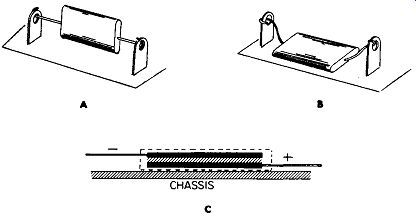
Fig. 5-1. Faulty installation of a capacitor producing undesirable coupling
to chassis.
Lead Length
Another common error is failure to recognize the effect of lead length on the resonant frequency of capacitors and their circuits. For example, changing the length from 0.5 to 0.3 inch can raise the resonant frequency of a disc ceramic by as much as 10 mhz. Other types may be affected even more.
Disc ceramics are pointed out because they are so common in miniature circuitry, and when components are tightly packed, there is always the temptation to make the replacement the easy way. Thus, in a critical circuit make certain the replacement's leads are the same length as the original's.
Soldering Precautions
Miniaturization has led to a new set of problems for the service technician-all components are smaller, and capacitors are no exception. Take the small Mylar types, for ex-ample. Naturally they must be soldered into the circuit. But the heat of the soldering iron or gun can ruin them unless proper precautions are taken. Always use a soldering device that provides no more heat than is needed. Prolonged application of a hot iron to the lead of a Mylar unit can melt the dielectric or the internal solder joint between lead and plate. A deft hand is the surest way to avoid this problem.
An excellent device for preventing heat damage is a set of surgical clamps. They are sold under a variety of trade names, and are well worth their small cost. In essence they are clamped onto the lead, between the component and iron, and act as a heat sink (absorb excessive heat). This principle is shown in Fig. 5-2.
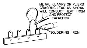
Fig. 5-2. Protecting capacitor from excess heat during soldering.
In summary, your best "tool" for capacitor replacement is good judgment, born of knowledge and experience. The most expedient thing to do, of course, is to always use the exact type as the original. But progress is synonymous with electronics ... even a three-year old radio can benefit by replacing an outmoded capacitor with a more modern one.