AMAZON multi-meters discounts AMAZON oscilloscope discounts
Although the semiconductor diode does not figure as prominently in audio-amplifier circuits as it does elsewhere, its applications in that area are noteworthy. Both active and passive diodes are used in AF systems to greatly simplify the circuitry needed to perform a given function. This section describes typical applications.
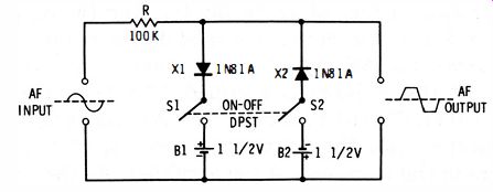
Fig. 3-1. Level clipper.
LEVEL CLIPPER
Automatic maintenance of signal amplitude at a constant level is often of great importance in AF amplification. For example, such amplitude limiting in the speech amplifier of a radio transmitter results in a higher average modulation level, increasing transmitter effectiveness in spite of variations in voice loudness. The limiting device must operate quickly.
Fig. 3-1 shows the circuit of a simple clipper. Here, each of two 1N81A high-back-resistance germanium diodes is reverse-biased by a 1.5-volt battery (B1 and B2) . The AF input signal is applied to these biased diodes simultaneously through series resistor R. Because of the bias, diode X1 cannot conduct forward current until the positive half-cycle of signal voltage exceeds +1.5 volts peak ; diode X2 cannot conduct forward current until the negative half-cycle of signal voltage exceeds -1.5 volts peak. Accordingly, from zero to the 1.5 volt peak, there is no voltage drop across R, and the output voltage increases uniformly from zero to 1.5 volts peak. But as soon as the peak amplitude of the input signal exceeds 1.5 volts, current begins to flow and produces a voltage drop across R. The higher the input amplitude, the greater the forward current and the higher the voltage drop. The result is that the amplitude of the output signal does not rise higher than + 1.5 volts and -1.5 volts.
Because of the high resistance of R, the external load of the clipper must be high (500K or more) to minimize insertion loss. Generally, this imposes no hardship, since the clipper may be operated between two tube stages where it works out of a medium-impedance plate into a high-impedance grid.
High-back-resistance diodes are employed to minimize reverse current leakage from the batteries. Although batteries are shown in the schematic, the bias voltage may also be obtained from a well-filtered DC power supply through suitable voltage dividers.
The squaring action of the clipper generates harmonics of respectable amplitude, and for this reason the clipper must be followed with a suitable low-pass filter to remove the distortion. The cutoff frequency of the filter depends upon range and fidelity requirements, 2,500 HZ or so being common in amplifiers and modulators for voice communication.
AMC RECTIFIER
Another system for automatically limiting the output of an audio amplifier is the automatic modulation control (AMC) . In this circuit, the AF output of the amplifier is sampled and a portion of this voltage is rectified. The DC output of the rectifier is then filtered to remove the AF component and applied in series with the normal bias to one of the tubes or transistors in the front end of the amplifier. As the output signal increases, the bias reduces the gain of the amplifier, and vice versa, thus holding the output constant. Although this system is not as rapid in action as the clipper shown in Fig. 3-1, neither does it generate the harmonics produced by the clipper.
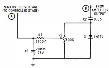
Fig. 3-2. AMC rectifier circuit.
Fig. 3-2 shows an AMC rectifier circuit. Lead B is connected to a signal point at or near the output of the amplifier. The sampled signal is applied to a shunt-diode rectifier consisting of C2, gold-bonded 1N277 germanium diode X, and potentiometer R2. Because of the high impedance of this rectifier circuit, the amplifier is loaded only negligibly. The negative DC output of the diode is filtered by C1 and R1, and the resulting negative bias voltage, which is proportional to the AF amplitude, is available at A. This voltage, which is continuously variable through adjustment of potentiometer R2, may be applied to the control grid or suppressor of a front-end stage in series with the normal bias of that stage. When a positive bias voltage is needed for some transistor amplifiers, diode X must be reversed.
AMC operates in an audio amplifier much the same as AGC does in an RF amplifier or receiver. Unlike an AC-operated audio AGC system, however, AMC utilizes a DC control voltage and therefore is not phase sensitive.
MAGAMP RECTIFIER
Most magnetic amplifiers operate in the audio-frequency spectrum and are finding increasing application in various areas of electronics. They can provide very high gain. If the power supply frequency is made high enough (10 khz or above ), a mag-amp may be used for sound reproduction.
Self-saturation improves the efficiency and control of a magnetic amplifier and is obtained by means of a semiconductor rectifier circuit. Power rectifiers must be used in magamps that deliver power output of 5 watts or more and operate at high voltages (100 volts and above ). In low-level units, such as preamplifiers, instrument amplifiers, and control amplifiers, lower-powered signal diodes may be used.
Fig. 3-3 shows a representative magamp circuit. For simplicity, the core is omitted in this schematic. L2 and L3 are the reactance windings, connected phase-bucking to prevent induction into the other two coils. L1 is the control winding, into which a DC control signal is introduced, and L4 is a feed-back winding for improving amplifier action through regeneration.
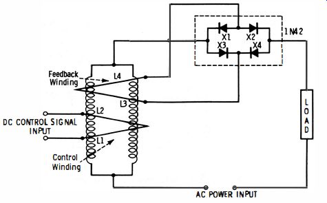
Fig. 3-3. Regenerative magamp.
The output of the magamp is connected to an AC power supply, load device, and the rectifier circuit in series. The rectifier unit, consisting of diodes X1, X2, X3, and X4, has a double function ; the load is supplied through two 2-diode legs in parallel (that is, X1-X2 and X3-X4), but the feedback winding is excited by full-wave pulses delivered by the four diodes acting as a bridge rectifier. For best operation, the forward conduction curves of the four diodes should be closely matched.
Completely assembled matched units containing four diodes are available under the name quad or varistor. The 1N42 shown in Fig. 3-3 is a 100-volt germanium plug-in unit which contains four matched diodes.
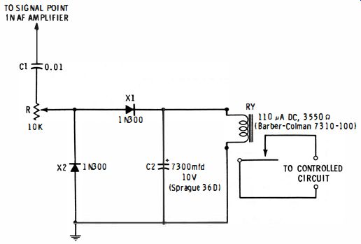
Fig. 3-4. Voice-controlled relay.
VOICE-CONTROLLED RELAY
A voice-controlled relay, operated from a speech amplifier, has numerous uses. One of these is to keep a radio transmitter or wired-radio intercom operating only as long as the operator is speaking. This frees the operator from working a switch.
Fig. 3-4 shows a voice-controlled relay circuit. The control signal is picked from any point in the speech amplifier which will yield an AF voltage of at least 2 volts rms at approximately 0.5 milliwatt. C1 is a blocking capacitor to isolate the diodes from DC components in the amplifier. The signal is rectified by the lN300 silicon junction diodes ( X1, X2) , and the resulting DC charges capacitor C2 and closes relay RY. Rheostat R is adjusted for closure of the relay on maximum AF signal.
When the signal is interrupted, the diodes have no output, but the voltage due to the charge in capacitor C2 holds the relay closed. C2 cannot discharge back through the high reverse resistance of X1, so it discharges slowly through the relay.
After an interval, the discharge current reduces the capacitor voltage sufficiently for the relay to drop out. (With the 7,300 mfd capacitor and 3,550-ohm relay specified in Fig. 3-4, this interval is approximately 3.5 seconds. ) The on interval may be lengthened by increasing the value of C2, or shortened by decreasing this capacitance.
TUNNEL DIODE AF AMPLIFIER
Fig. 3-5 is the circuit of an experimental tunnel diode audio amplifier. This circuit provides a gain of approximately 20 db at 1,000 HZ and operates into a 100-ohm load. Input impedance is of the order of 200 ohms.
For highest gain and best linearity, the operating point of the 1N3712 germanium tunnel diode (X) must be set to the center of the negative-resistance region of the forward conduction characteristic, by adjustment of rheostat R3. This is done most readily by applying a 10-millivolt rms, 1,000- HZ, sine-wave signal to the AF Input terminals and adjusting R3 for highest amplitude and lowest distortion of the output signal, as viewed with an oscilloscope at the AF Output terminals.
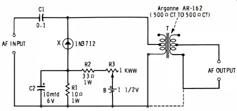
Fig. 3-5. Tunnel diode AF amplifier.
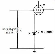
Fig. 3-6. Diode as cathode resistor.
Care must be taken that the circuit does not break into oscillation, either with or without an input signal. To prevent oscillation with some diodes, it may be necessary to alter the resistance of R1.
Output transformer T has a 1:1 turns ratio and very low DC resistance. Only one half of the primary and one half of the secondary are used. The transformer has a full-winding impedance ratio of 500-to-500 ohms.
DIODE AS CATHODE RESISTOR
Automatic bias in a tube-type amplifier or oscillator may be supplied to advantage by a zener diode, as shown in Fig. 3-6.
From the various available types, a diode should be selected which has the desired bias voltage at the center of its zener region, and for which the maximum DC cathode current of the tube will furnish the corresponding zener current.
The advantages of this scheme are that the tube current can vary considerably without materially changing the bias voltage developed across the diode, and that the dynamic impedance of the diode is so low that no cathode bypass capacitor is required.