AMAZON multi-meters discounts AMAZON oscilloscope discounts
The ability of the diode to rectify, switch, demodulate, or provide nonlinear resistance makes this device suitable for use in many control circuits where more complicated devices would otherwise be needed for comparable operation. Such application include the operation of a DC relay from AC or RF, separation and routing of DC control signals, and switching DC control signals.
This section describes several practical control applications of diodes which are indicative of the scope, but they by no means exhaust the applications possibilities. Diodes may be found in industrial and amateur electronic circuits where it is necessary to change AC to DC, hold back a DC signal, limit signal amplitude, or alter the shape of a response curve.
AF-RF RELAY
Fig. 5-1 shows a simple circuit for adapting a sensitive DC relay to operation at AF or RF up to 200 megacycles. Two 1N56A high-conductance germanium diodes ( X1 and X2) are employed in a half-wave rectifier circuit. Table 5-1 gives the input AF or RF voltage (rms) required to close various commercial relays in this circuit.
Capacitor C1 (1,000 mmf) is not needed unless the signal source has a DC voltage in its output; when such a voltage is present, the diodes must be protected from it by means of the blocking capacitor. At audio frequencies of 1,000 HZ and lower, it may be necessary to connect a capacitor (0.1 mfd or higher) in parallel with the relay coil to prevent chatter.
---------------
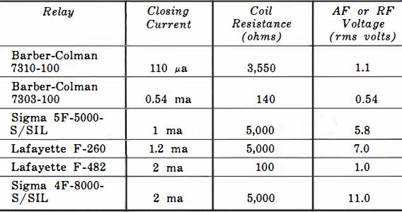
Table 5-1 . AF-RF Relay Operating Data
Relay Closing Coil AF or RF Current Resistance Voltage (ohms) (rms volts)
Barber-Colman 7310-100 110 /La 3,550
Barber-Colman 7303-100 0.54 ma 140
Sigma 5F-5000 SjSIL 1 ma 5,000
Lafayette F-260 1.2 ma 5,000
Lafayette F-482 2 ma 100
Sigma 4F-8000 SjSIL 2 ma 5,000 1.1
0.54 5.8 7.0 1.0 11.0
--------------------
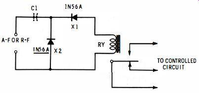
Fig. 5-1. AF-RF relay.
TUNED RF RELAY
A simple tuned circuit will enable the diode rectifier-type relay to be operated from a transmitted radio signal. Fig. 5-2 shows the circuit.
Tuned circuit L and C values must be chosen for resonance at the desired signal carrier frequency. If C is a 365-mmf variable capacitor, plug-in coils may be used to cover the spectrum between the low end of the standard broadcast band and 50 mc. Suitable components for the 27.255-mhz citizens' control frequency a 1/2 h-inch-diameter form.
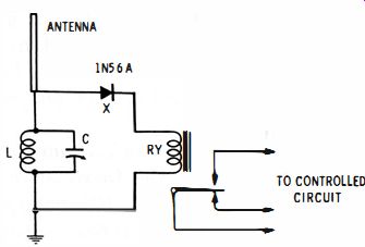
Fig. 5-2. Tuned RF relay.
With this combination, 27.255-mhz response is obtained at about half-maximum setting of the tuning capacitor.
The pickup antenna may be any available whip, rod, or flat top which will operate at the signal frequency. A good ground is essential for maximum sensitivity.
Best sensitivity will be obtained with a low-current, low voltage relay, such as the 110-microampere, 3,550-ohm unit listed in Table 5-1. Where field strength is high, one of the less sensitive relays may be used.
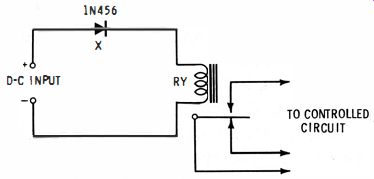
Fig. 5-3. Polarity-sensitive DC relay.
POLARITY-SENSITIVE DC RELAY
The circuit given in Fig. 5-3 provides a DC relay which will operate only when the applied control voltage has the proper polarity. In this arrangement a 1456 silicon-junction diode has been forward-connected in series with sensitive DC relay RY. The diode acts as a polarity-sensitive switch. When a positive voltage of the proper value is applied to the top input terminal, forward current flows readily through the diode and picks up the relay. But when the polarity of the control voltage is reversed, the diode becomes reverse-biased and can pass only a few thousandths of a microampere-to all practical intents and purposes representing an open switch-and the relay remains dropped out. This circuit has been used as an alarm in systems in which monitored voltage is subject to polarity shifts.
A portion of the control voltage is lost across the diode, because of the voltage drop due to the forward resistance of the diode. Table 5-2 shows the actual DC voltage required to operate sensitive relays of several types in this circuit. The same principle may be utilized with a higher-current (low sensitivity) relay by using a small rectifier in place of the diode.
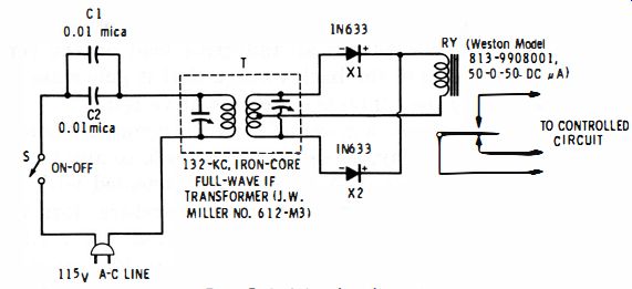
Fig. 5-4. Wired-radio relay.
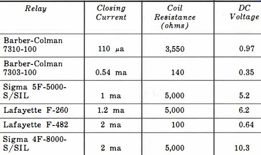
Table 5-2. Polarity-Sensitive Relay Operating Data
WIRED-RADIO RECEIVER
Wired-radio (carrier-current) systems provide an excellent means for remote control of electrical equipment of all kinds.
The RF control signal is transmitted over the power line to the receiver so that under proper operating conditions there is no radiation into space with attendant interference, and no special wires need be run.
If only a short or medium distance is to be covered, a sensitive wired-radio control receiver may be built without tubes, transistors, or other amplifying components. Fig. 5-4 shows a receiver circuit employing two 1N633 high-conductance germanium diodes in a full-wave rectifier-detector. The circuit responds to a 132-khz CW signal and operates a 50-microampere, 1,000-ohm DC relay (RY) . The tuner (T) is a 132-khz, iron-core, IF transformer that is pre-tuned to resonance with the control signal. The primary winding of this transformer is connected to the AC power line through a 0.02-mfd 500-volt mica blocking capacitor (two 0.01-mfd units, C1 and C2, connected in parallel). This capacitor prevents short circuit of the line by the transformer but affords relatively easy passage of the control signal, since the reactance of C1 and C2 at 60 HZ is 0.133 megohm but only 60 ohms at 132 khz.
To pre-tune the receiver to the 132-khz signal on the power line, close switch S and adjust the trimmers of transformer T to the point at which the relay closes. Interrupt the signal at the transmitter and note that the relay opens. The receiver will require no subsequent tuning unless the control-signal frequency is changed.
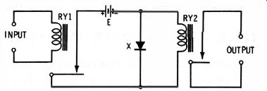
Fig. 5-5. Relay contact protector.
RELAY CONTACT PROTECTOR
A great many control circuits use two relays-a sensitive one which responds to the signal and then closes a more rugged one which, in turn, actuates the controlled equipment. The coil of the second relay constitutes an inductive load on the contacts of the first one, and the back voltage that it generates on turn-off can destroy the contacts of the sensitive relay.
To prevent this damage, a diode (X) may be connected across the coil of the second relay, as shown in Fig. 5-5, to absorb the dangerous transient. This diode is reverse-connected with respect to the local power supply (E) and therefore does not pass appreciable current, nor does it short-circuit relay RY2.
When the contacts of RY1 open, however, the collapsing magnetic field induces a transient voltage across the coil of RY2, and the polarity of this high voltage is such that the anode of the diode now is positively biased. Consequently, the diode exhibits low forward resistance which absorbs the transient and protects the contacts of RY1.
Small selenium diodes are available for this application under the name contact protector diode ; they are offered in a wide variety of ratings, including relay coil currents up to 2 amp and coil voltages up to 154 volts. For AC operation, two diodes may be connected back-to-back (single units of this double-anode construction also are available).
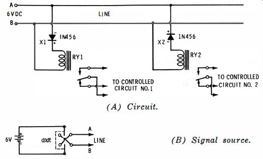
Fig. 5-6. Multiple control over two-wire line.
(A) Circuit. (B) Signal source.
MULTI PLE CONTROL OVER TWO-WIRE LINE
Fig. 5-6A shows a scheme for operating at will either one of two remotely located relays over a single two-wire line. A 6-volt DC control signal is used.
In series with each 1-ma, 5,000-ohm relay (RY1, RY2 = Sigma 5F-5000-S/SIL) is connected a 1N456 silicon junction diode ( X1, X2) . When the polarity of the control signal is such that line A is positive, X1 passes forward current which picks up relay RY1. At this time, however, X2 is reverse-biased and effectively opens the circuit through relay RY2. When the control-signal polarity is reversed, line A becomes negative, X1 is reverse-biased and relay RY1 drops out, and X2 passes forward current which picks up relay RY2.
Thus, a simple DPDT reversing switch (Fig. 5-6B) at the control point will permit individual control of the relays.