AMAZON multi-meters discounts AMAZON oscilloscope discounts
Long before World War I, the early crystal detector was first used with a sensitive DC galvanometer to measure the strength of radio signals ; later, the crystal and meter combination was widely used as a resonance indicator in absorption wavemeters. Thus did the semiconductor enter electronic instrumentation. During the 1920's, after invention of the copper oxide rectifier, the same scheme was used for the first time to measure low-frequency voltage-with a miniature rectifier driving a DC milliammeter.
The stable, wide-range diodes available after World War II greatly extended the development of test instruments needing no local power. In recent years, further extensions have been afforded by the tunnel diode, varactor, and biased diode which require a small amount of local power.
Whereas the diode long was important in instrumentation only as a meter rectifier, and still is so used to advantage, its properties as a valve, switch, modulator, demodulator, limiter, capacitor, and nonlinear resistor suit it to many other applications in electronic instruments. The instrument applications reported only since 1950 comprise a substantial literature. All types of diodes have been used and are being constantly investigated.
SENSITIVE DIODE METERS
The copper oxide rectifier has a long record of service as a meter rectifier, but responds relatively poorly to high frequencies. The response of a good, miniature, copper oxide meter rectifier at 10 khz, for example, has been observed to drop 10r o; and at 100 khz, 30ro with respect to its response at 100 HZ. This limits a meter employing this type of diode to the AF spectrum. The miniature selenium diode likewise is restricted to AF meters. Germanium and silicon point contact diodes, on the other hand, operate over a wide frequency range extending to 200 mhz for germanium and to several thousand mhz for silicon, and so adapt a DC meter for response at radio, as well as audio, frequencies.
A rectifier-type meter may be equipped with multiplier resistors for measurements of voltage in several ranges, or with shunt resistors for measurement of current. However, the basic instrument itself, consisting of meter and diode (s), is useful as a sensitive voltmeter, milliammeter, or microammeter. Because of its simplicity and power-free operation, a diode meter of this type often is included in other test equipment, such as signal generators, bridges, and RF meters, for monitoring a signal.
(A) Circuit.
(C) 0-100 DC microammeter.
(B) 0-1 DC milliammeter.
(D) 0-50 DC microammeter.
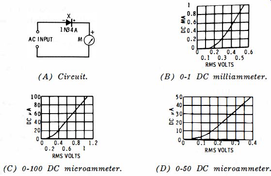
Fig. 6-1 . Series-diode meter.
Figs. 6-1 to 6-9 show diode meter circuits and their performance. In each instance where practicable, data are given for the three current meters most apt to be used by equipment builders and experimenters : 0-1 DC milliammeter (internal resistance 55 ohms) , 0-100 DC microammeter (internal resistance 825 ohms) , and 0-50 DC microammeter (internal resistance 2,000 ohms).
These circuits are described separately in this section in the section on voltmeters, or in the section on current meters.
The semiconductor used in each circuit is the 1N34A general purpose germanium diode ; however, point-contact sil icon diodes also are usable. Each circuit should be calibrated individually since diodes vary in response; the performance curves given in the illustrations are derived from measurements made with a typical 1N34A. In each circuit, a calibration control rheostat may be connected in series with the DC meter (M) for standardization at full-scale deflection.
The 0.01-mfd capacitor (C in Figs. 6-2 and 6-3 ) is a good compromise value for AF and RF operation.
SENSITIVE DIODE VOLTMETERS
Series-diode type--This is the simplest possible voltmeter, consisting of a diode and DC meter in series (Fig. 6-1A). Here, the diode functions as a simple half-wave rectifier, passing to the meter only positive half-cycles of the input voltage (if the diode and meter are reversed, the circuit will respond instead. to negative half-cycles). Response with a 0-1 DC milliammeter is given in Fig. 6-1B, with a 0-100 DC microammeter in Fig. 6-1C, and with a 0-50 DC microammeter in Fig. 6-1D. This circuit suffers from the necessity that the DC return path for the diode and meter must be completed by the circuit supplying the voltage. The meter reading therefore is affected inversely by the external resistance (measurements for the curves in Fig. 6-1 were made with an AC generator having an output resistance of 50 ohms ). When this resistance is constant, however, as it often is in instruments in which the voltmeter is installed, this imposes no difficulty. A second hazard, which is not so easily ignored, is the fact that DC from the circuit under test may damage the diode and meter.
At frequencies under 60 HZ, it may be necessary to connect a large capacitance in parallel with meter M to prevent vibration of the pointer.
Two-diode half-wave type-The addition of a second diode, X1 (Fig. 6-2A), allows the use of a DC-blocking capacitor (C) , thus overcoming one of the shortcomings of the circuit shown in Fig. 6-IA. This second circuit also is a half-wave arrangement, diode X2 rectifying the positive half-cycle of input voltage. Diode X1 is reverse-connected for the positive half cycle and so appears as a high resistance. When the input polarity reverses, X2 then is reverse-biased while X1 is forward-biased by the negative half-cycle. X1 accordingly conducts readily, protecting X2 from the high peak inverse voltage (due to presence of capacitor C) which it otherwise would be forced to withstand.
(A) Circuit. (B) 0-100 DC micro-ammeter. (C) 0-50 DC micro-ammeter.
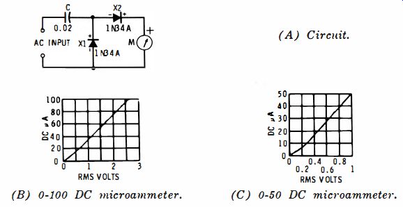
Fig. 6-2. Two diode half-wave meter.
(A) Circuit. (B) 0-100 DC microammeter. (C) 0-50 DC microammeter.
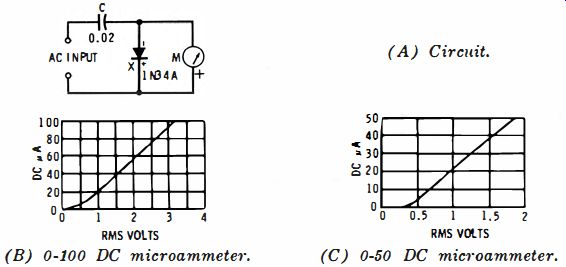
Fig. 6-3. Shunt diode meter.
(A) Circuit. (B) 0-1 DC milliammeter. (C) 0-100 DC microammeter. (D) 0-50 DC microammeter.
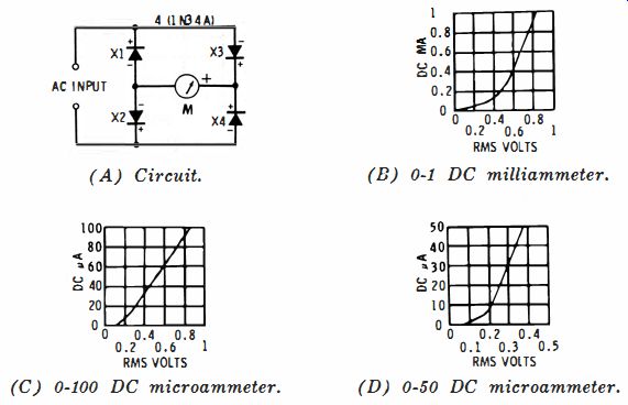
Fig. 6-4. Full-bridge meter.
The response curves given in Figs. 6-2B and 6-2C show this circuit to be more sensitive than the simple half-wave rectifier described in the preceding discussion. The 0-1 DC milliammeter is not specified here because of the higher AC input voltage required when this meter is used removes this circuit from the sensitive meter category.
Shunt-diode type--This circuit is popular because it contains a blocking capacitor, and yet requires only one diode (Fig. 6-3A) . It is so termed because, unlike the circuit of Fig. 6-1A, the diode shunts the meter and input.
Figs. 6-3B and 6-3C show the response of the circuit using a 0-100 DC microammeter and 0-50 DC microammeter, respectively. The 0-1 DC milliammeter is not specified here for reasons given earlier. From the response curves, it is seen that the shunt-diode meter is less sensitive than the series diode and two-diode types previously described.
Full-bridge type--This circuit provides full-wave rectification and may be used with a DC-blocking capacitor if necessary (Fig. 6-4A). Because it uses the energy in both half-cycles of the AC input voltage, its DC output (and accordingly the sensitivity of the circuit) is greater than with any of the previously described circuits. For highest efficiency, the four diodes should be matched.
Figs. 6-4B, C, and D show the response with each of the three DC meters: 0-1 milliammeter, 0-100 microammeter, and 0-50 microammeter.
An added merit of this circuit is the fact that the ripple component in the DC meter current is twice the AC input frequency. This often eliminates the need to bypass meter M at low audio frequencies.

Fig. 6-5. Half-bridge meter.
(A) 0-100 DC micro-ammeter. (B) 0-50 DC microammeter.
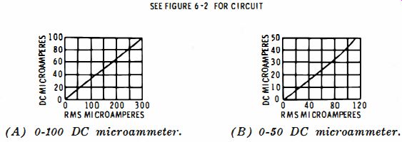
Fig. 6-6. Current-meter performance (Two-diode half-wave circuit).
Half-bridge type-Where economy is imperative although full-wave rectification is demanded, two of the diodes of the bridge rectifier may be replaced with resistors. This gives the half-bridge circuit shown in Fig. 6-5A. As the curves in Figs. 6-5B, C, and D show, the half-bridge is less sensitive than the full bridge with either of the DC meters.
The half-bridge circuit, like the full bridge, may be used with a DC-blocking capacitor when necessary.
SENSITIVE DIODE CURRENT METERS
The meters shown in Figs. 6-2A, 6-3A, 6-4A, and 6-5A may be used as AF -RF current meters, as well as voltmeters. For current measurements, however, the two circuits with blocking capacitors (Figs, 6-2A and 6-3A) may be used only in setups where insertion of the capacitor is permissible.
Figs. 6-6, 6-7, 6-8, and 6-9 show performance of these circuits with the same DC meters previously specified.
(A) 0-100 DC microammeter. (B) 0-50 DC microammeter.
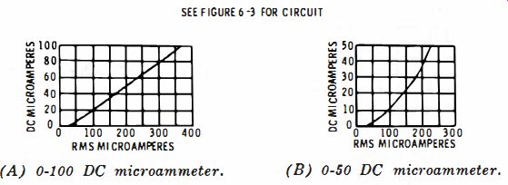
Fig. 6-7. Current-meter performance (Shunt-diode circuit).
(A) 0-1 DC milliammeter
(B) 0-100 DC microammeter.
(C) 0-50 DC microammeter.
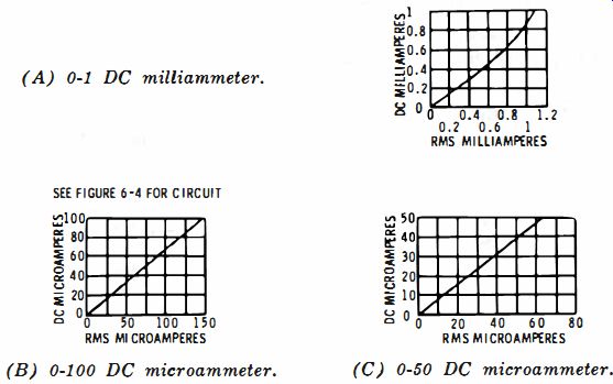
Fig. 6-8. Current-meter performance (Full-bridge circuit).
(A) 0-1 DC milliammeter.
(B) 0-100 DC microammeter.
(C) 0-50 DC microammeter.
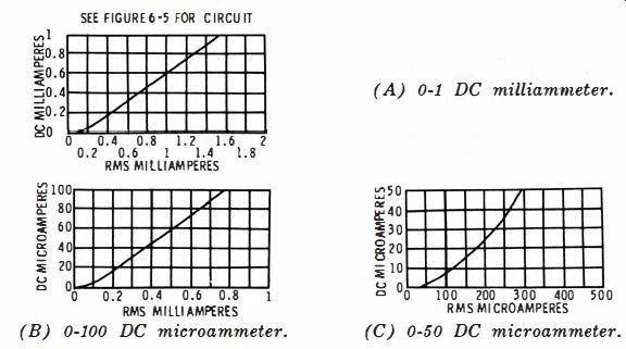
Fig. 6-9. Current-meter performance (Half-bridge circuit)
SQUARE-LAW AC METER
The full-bridge circuit (Fig. 6-4A) with a 0-50 DC micro-ammeter may be used as a square-law AF-RF voltmeter. The response curve (Fig. 6-4D) shows the circuit action to be approximately square-law (doubling the input voltage quadruples the output current) over much of its slope.
Close square-law response may be obtained by picking matched diodes for the bridge. Often a carefully picked single diode will give square-law response in the series-diode circuit (Fig. 6-1A) with the 0-100 DC microammeter.
SQUARE-LAW DC METER
Fig. 6-10A shows the circuit of a square-law DC meter. This circuit utilizes the nonlinear forward conduction of a single lN34A general-purpose germanium diode.
The response curve (Fig. 6-10B ) shows operation to be exactly square-law at DC input voltages between 0.1 and 0.2 volt. Resistance of the DC source should not exceed 100 ohms.
Careful picking of a diode from an ample supply will insure close square-law response.
This circuit may be employed also as a square-law detector or squaring circuit for computers by substituting a 2,000-ohm resistor for the microammeter. Output-voltage changes measured across this resistor then will be proportional to the square of input-voltage changes.
(A) Circuit. (B) Response.
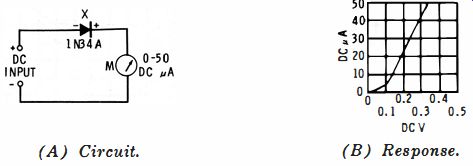
Fig. 6-10. Square-law DC meter.
QUASI-LOGARITHMIC DC VOLTMETER
The scale of a logarithmic voltmeter is spread out in its lower section and compressed in its upper section. The result is that two or more decades of voltage may be read on the single scale with the same accuracy and convenience which would require two voltage ranges on a regular linear voltmeter. This saves the labor of range switching.
Logarithmic voltmeters, both AC and DC, usually employ complex multistage tube or transistor circuits. But quasi-logarithmic action may be obtained with a biased diode. The circuit (Fig. 6-1 1A) is essentially a diode limiter biased at + 1 volt DC and a high-resistance DC voltmeter for reading the limiter output. The voltmeter section is composed of a 0-50 DC microammeter (M) and 50K multiplier resistor (R3) . The bias is set to exactly 1 volt by adjustment of rheostat R2. Because of the extremely high reverse resistance of the 1N300 silicon junction diode (several thousand megohms ), the bias cannot deflect the microammeter.
(A) Circuit. (B) Meter scale.
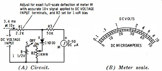
Fig. 6-11. Quasi-logarithmic DC voltmeter. Adjust for exact full-scale deflection
of meter M with accurate 10 v signal applied to DC VOLTAGE.
Up to 1 volt DC input, the diode cannot pass current, because of its positive bias. Response of the circuit (Fig. 6-11B) therefore is closely linear up to 1 volt. Beyond 1 volt, however, the diode passes forward current and compresses the upper half of the meter scale. This action affords a scale on which may be clearly read 0.1-1-10 volts. A second, 10-100-1,000 volt range, may be obtained by means of a suitable voltage divider connected ahead of the circuit. High input resistance may be obtained with a transistor- or tube-type DC amplifier ahead of the circuit.
TRANSFORMER-COUPLED LINEAR AF MILLIAMMETER
Fig. 6-12 shows the circuit of a transformer-coupled AF milliammeter. A special feature of this instrument is its low insertion loss ; the impedance of the primary winding of transformer T is so low that insertion of the instrument into a test circuit introduces very little voltage drop. Current ranges are 0-3, 0-10, 0-30, and 0-100 ma rms. The indicating instrument is a 0-50 DC microammeter (M) , and response of the circuit is linear.
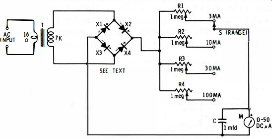
Fig. 6-12. Transformer-coupled linear AF milliammeter.
Rectification is provided by a full bridge (X1 to X4) . The diodes in this bridge may be four general-purpose germanium diodes, such as Type 1N34A, or a miniature bridge-type copper oxide meter rectifier (such as Conant B-160) may be used in place of the four separate diodes. The circuit was tested with both. Transformer T is a midget universal audio output unit with connections to the 16-ohm primary and 7,000-ohm secondary taps.
Calibration rheostats R1 to R4 are miniature 1-megohm units. Only the full-scale deflection in each current range need be calibrated, since the response is linear.
1. Set RANGE switch S to its 3 ma position.
2. Feed an accurate 3 ma rms current into the AC INPUT terminals.
3. Adjust R1 for exact full-scale deflection of meter M.
4. Repeat this procedure, setting S successively to its 10, 30, and 100 ma positions, applying input current of 10, 30, and 100 ma, respectively, and adjusting rheostats R2, R3, and R4, respectively.
Frequency response of the instrument depends upon the characteristics of transformer T; the better the grade of the transformer, the wider the frequency response.
ZENER DIODE METER PROTECTOR
The sharp "breakdown" of a zener diode from its previous high-resistance state may be utilized to protect a DC meter from burnout. Fig. 6-13 shows the circuit of a 50-volt, 20,000 ohms-per-volt voltmeter protected by a 1N714 10-volt zener diode (X).
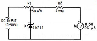
Fig. 6-13. Zener diode meter protector.
Here, the indicating meter (M) is a 0-50 DC microammeter, the scale of which reads 0-50 volts without mental addition of ciphers. R2 is the principal voltmeter multiplier resistor. Potentiometer R1 is set so that, with 51 volts applied to the DC INPUT terminals, the diode begins to conduct in its zener region. After this adjustment, the diode acts as an extremely high resistance as long as the input voltage is between zero and 50 volts ; no voltage drop due to diode current is produced across R1, and the meter accuracy is not affected. As soon as the input exceeds 50 volts, however, the diode conducts and the resulting voltage drop across R1 prevents over-swing of the meter.
This is a fast-acting system which will protect any sensitive meter in a similar circuit.
ZENER DIODE VOLTAGE STANDARDS
The regulating characteristic of a zener diode biased to its breakdown region may be used as a source of accurate voltage.
A single diode operated from a battery or well-filtered DC power supply will deliver a standard DC voltage, and a double anode diode (or two single-anode units connected back-to-back) operated from the low-voltage secondary of a transformer will provide a standard, squared AC voltage. These applications are described in Section 4.
Additionally, a DC voltage standard having exceptional stability is shown in Fig. 6-14. This circuit combines the long-term voltage stability of the mercury battery and the regulating property of the 651C5 zener diode. It is much less expensive than a standard cell, in lieu of which it may be used in the low-budget laboratory.
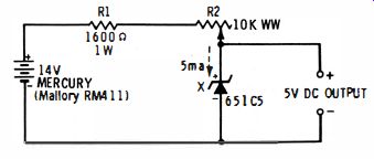
Fig. 6-14. Zener diode voltage standard.
In this circuit, rheostat R2 is set for a diode current slightly in excess of 5 ma. (This current level may be checked by reading the voltage drop across R1 with a DC VTVM. The deflection should be 8 volts. ) R1 is a current-limiting resistor which protects diode X from current overload when R2 is set to its extreme low-resistance point. A standard voltage output of 5 volts is provided by this circuit.
RF PROBE
Fig. 6-15 shows the circuit of an RF probe for DC VT voltmeters. The small size of the 1N55AS miniature germanium diode (X) , 0.02-mfd ceramic capacitor C, and I-megohm 0.5-watt resistor R permits enclosure of these components in a slender test-probe shell.
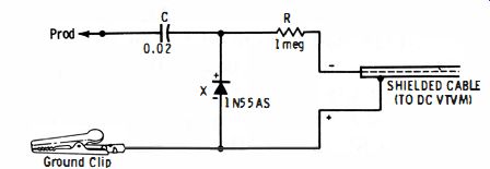
Fig. 6-15. RF probe.
DC output voltage of the circuit is equal to the peak value of the RF input voltage (that is, Edc = 1.414 Erm. ) and it is this value that is indicated directly by the DC scales of the VTVM. Most DC VTVMs have an input resistance of 11 megohms, 1 megohm of which is in the DC probe. Resistor R takes the place of this probe resistor. It also serves as an isolation resistor. If R is made 4.14 megohms (one 3.9-megohm and one 0.24-megohm resistor in series) , the voltage division with the 10 megohms contained in the VTVM will cause the meter to read rms volts instead of peak volts, if this is desired. With the 1N55AS, the probe will handle up to 50 volts rms.
With the diode polarized as shown, the circuit responds to the positive peak of the RF signal. For negative-peak measurements, reverse the diode and the DC input to the VTVM.
PEAK-TO-PEAK PROBE
Fig. 6-16 is the circuit of a voltage doubler-type probe which will adapt a DC VTVM for measurement of peak-to-peak AC voltages. This is essentially two 1N55AS shunt-diode rectifier circuits (of the type previously shown in Fig. 6-15) connected in parallel. X1 rectifies the positive peak of the AC input, and X2 the negative peak.
Fig. 6-16. Peak-to-peak probe.
The DC voltage across each load resistor is equal to the peak value of the corresponding half-cycle of AC input voltage; the positive peak voltage across R2 and the negative peak voltage across R3. Since R2 and R3 are in series and their voltages are of opposite polarity, the voltage at their outside ends is the sum of these two separate voltages, and thus is equal to the peak-to-peak value of the AC input voltage. It is this total DC voltage that is applied to the DC VTVM. Maximum signal input should not exceed 100 volts peak-to-peak.
Resistor R1 takes the place of the 1-megohm isolating resistor which is in the DC probe of the VTVM. Omission of this resistance would impair the accuracy of the voltage readings.
DEMODULATOR PROBE
In order to examine the envelope waveform of an AM signal with an oscilloscope, the signal first must be demodulated.
After the complex TV video wave is demodulated, for example, the video modulation and sync pulses are visible.
Fig. 6-17 is the circuit of a low-capacitance demodulator probe for operating into the vertical channel of an oscilloscope.
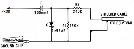
Fig. 6-17. Demodulator probe.
This is a shunt detector with a DC-blocking capacitor (C) . The 1N55AS is a miniature 150-volt germanium diode. This voltage rating allows safe handling of 50 volts peak signal amplitude.
The input impedance of the probe is high enough that use of this accessory will not upset operation of most TV circuits.
FIELD STRENGTH METER
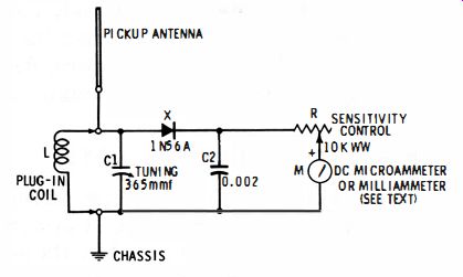
Fig. 6-18. Field-strength meter.
A tunable diode detector with indicating meter makes a simple field strength meter and absorption wavemeter. The tuning dial may be calibrated with an RF signal generator.
Fig. 6-18 shows the circuit of an instrument of this type.
The tuner consists of coil L and 365-mmf variable capacitor C1. (If wide-band operation is desired, a series of plug-in coils may be used to cover the frequency range. Table 6-1 gives plug-in coil data. ) The manufactured coils specified in Table 6-1 cover the tuning range 260 khz to 100 mhz in five bands.
These are miniature, ceramic, slug-tuned coils which may be set exactly to frequency during the calibration of the instrument. For plug-in purposes, these coils may be mounted inside 1" -diameter 4-prong coil forms, such as Millen Type 45004.
For narrower-band tuning than is afforded by this coil assortment (example: amateur or citizens' bands ), a lower capacitance (for example, 50 or 100 mmf) should be used for C1.
The signal rectifier is a high-conductance 1N56A germanium diode (X) . DC output of this diode drives current meter M. The meter may be a 0-1 DC milliammeter or a 0-50 or 0-100 DC microammeter. The micro-ammeters provide highest sensitivity. The sensitivity control rheostat (R) allows reduction of the DC to the full-scale deflection of the meter on strong RF signals. The pickup antenna may be any convenient vertical wire, rod, or whip.
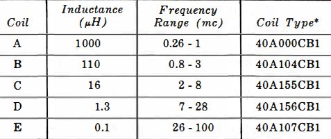
Table 6-1. Field Strength Meter Coil Data
The instrument may be calibrated by loosely coupling coil L to an RF signal generator, tuning-in generator signals at selected frequencies by adjusting C1 for peak deflection of meter M, and graduating the C1 dial accordingly.
PERCENT MODULATION METER
Fig. 6-19 is the circuit of a direct-reading percent modulation meter for checking AM transmitters. It also serves as a carrier shift meter and aural phone monitor. Its use of separate carrier and modulation meters eliminates the error and accidents caused when a single meter is shifted between these two functions.
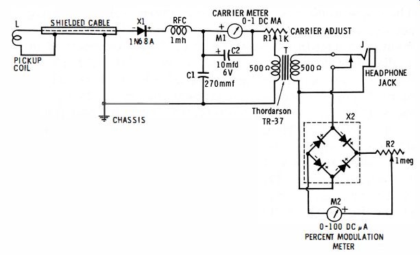
Fig. 6-19. Modulation meter.
The AM signal is picked up with a small coupling coil, L (2 or 3 turns of insulated hookup wire 2" in diameter), placed near the transmitter tank. This signal is demodulated by the lN68A germanium diode ( X1) . The diode output contains a DC component which is proportional to the average carrier voltage and is indicated by milliammeter Ml. The diode output also contains an AF component which is proportional to the modulation percentage, and which is indicated, after rectification by the transformer-coupled B-160 copper oxide bridge (X), by microammeter M2.
The instrument is set by adjusting rheostat R1 so that M1 reads exactly 1 ma when the circuit is excited by the transmitter. The deflection of this meter does not change during modulation unless carrier shift is present in the signal. Next, with the transmitter modulated 100%, as determined by measurements with an oscilloscope, rheostat R2 is set for exact full-scale deflection of M2. This is the 100 % modulation point, the 0-100 scale of M2 being read direct in percent modulation.
M2 does not deflect unless the signal is modulated ; the copper oxide does not respond to RF which could arrive only in small amounts through transformer T and through stray pickup.
Rheostat R2 needs no readjustment except during subsequent periodic check of calibration. R1, however, must be adjusted each time the instrument is used, to set M1 to full scale.
Transformer T (Thordarson TR-37) has a 1:1 turns ratio.
The closed-circuit jack (J) is provided for headphones for aural monitoring of the signal. Either magnetic or crystal headphones may be used.
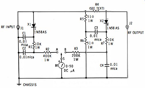
Fig. 6-20. SWR meter.
SWR METER
Fig. 6-20 shows the circuit of a conventional, bridge-type instrument for checking standing wave ratio of antennas, transmission lines, and RF components at frequencies up to approximately 100 mhz. Here, the RF bridge circuit consists of R4 and R5 in one leg, and R3 and the external device connected to coaxial jack J2 in the other leg. The RF signal is fed into the circuit via coaxial jack J1. Meter M reads this input signal when switch S is thrown to its position A, and the bridge output signal when S is thrown to B. All resistors must be 1-watt, 1%, noninductive units. The resistance of R4 must equal exactly the impedance of the transmission line, antenna, or component connected to jack J2 for test, otherwise the bridge will not null. Common impedance values met in practice are 52, 75, 300, and 600 ohms.
When R4, R5, and R6 have the exact specified values, the bridge will null at the selected "J2 impedance." That is, meter M will read zero when S is at position B and the bridge is excited by RF input. The layout of the instrument must be carefully planned to minimize stray capacitance, inductance, and coupling, and fully shielded to prevent RF pickup from the fields always present when this type of measurement is made.
After checking the completed instrument for clean null (with the highest-frequency signal to be used injected at J1, switch S set to B, and a noninductive dummy resistor equal to R4 connected to J2) and making any adjustments to the internal resistors needed to reduce null to zero, make an SWR calibration in the following manner;
1. Apply a 2-mc signal to J1.
2. Plug dummy resistor into J2.
3. Throw switch S to position A and adjust signal amplitude for full-scale deflection of M.
4. Transfer switch S to position B; M should read zero.
5. Connect a higher-resistance dummy resistor to J2.
6. Throw switch S to position A and reset signal amplitude for full-scale deflection of M.
7. Throw switch S to position B, note deflection of M, and record as E1.
8. Repeat steps 5, 6, and 7, using dummy resistors of various values and recording the corresponding meter readings as E2, E3, E4, etc.
9. Using these resistance values, calculate the values of standing wave ratio : SWR = Rl/R2 or R2/R1.
Here, R1 is the normal dummy equal to R4 in the circuit, and R2 is the resistance of the test dummy. Use the fraction in which the higher resistance is in the numerator. Draw a curve plotting these SWR values against the corresponding deflections of the meter, or prepare a direct-reading SWR scale for meter M. To use the instruments:
1. Connect RF source (such as transmitter) to J1.
2. Connect load (such as transmission line) to J2.
3. Place switch S in position A and adjust RF for full-scale deflection.
4. Throw switch S to position B and read meter.
5. Determine SWR from data obtained in step 9 in the preceding procedure.
(A) CW method. (B) AM method.
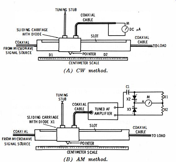
Fig. 6-21. Microwave SWR setups.
DIODE IN MICROWAVE SWR MEASUREMENTS
Whereas the instrument shown in Fig. 6-20 is adequate for SWR measurements at frequencies up to 100 mhz or more, a different technique must be employed at microwave frequencies. In the latter spectrum, a slotted line is used for SWR measurement. The rectifier or demodulator employed in these measurements is a sil icon point-contact microwave diode which must be selected to operate at the highest test frequency.
There are two methods. Fig. 6-21A may be used with an unmodulated (CW) signal; Fig. 6-21B requires an amplitude
modulated signal. In each method, the slotted line is essentially a segment of air-dielectric coaxial line, or wave guide, in which a lengthwise slot has been cut in the outer conductor.
A snug-fitting "carriage" slides over this slot and dips the metal tip of a microwave diode into the interior. This tip, acting as an antenna, samples the standing wave field within the tube, and the resulting DC output of the diode deflects DC microammeter M. A pointer attached to the carrier moves along a centimeter scale to indicate the position of the probe.
As the probe passes through a high-intensity point, M peaks in deflection (I1) and when it passes through a low-intensity point, M dips (I2) . The corresponding points (D1, D2, respectively) read on the centimeter scale may be used to calculate the frequency. The standing wave ratio is calculated from the maximum and minimum current readings using the formula:
SWR = I1/I2
The more sensitive method is illustrated by Fig. 6-21B. Here, an amplitude-modulated signal is fed into the slotted line.
The diode in the sliding carriage demodulates the signal, delivering AF output to an amplifier sharply tuned to the modulation frequency. The amplifier output is rectified by an audio-frequency half-bridge (X2-X3-R1-R2 ) and deflects microammeter or milliammeter M. Adjustments are the same as in the preceding example. Usually, however, the meter is direct-reading in volts (E1 = maximum, E2 = minimum), and SWR = E1/E2.
In each of the two systems, the meter scale may be made direct-reading in SWR units, with the lowest value at full scale. The RF signal amplitude then is first set for full-scale deflection when the carriage is at a peak point. When the carriage then is moved to the adjacent minimum, the meter will indicate SWR directly. Thus, if peak deflection is set at 100 microamperes, and dip falls at 89 }La in the method shown in Fig. 6-21A, SWR = 100/89 = 1.12. With each of the two systems, frequency may be measured in terms of the positions of D1 and D2, measured in centimeters between adjacent peak points or adjacent dip points using the formula:
The SWR meters just described may be used to measure RF power when the meter is inserted between the signal source and the normal load, the slotted line being terminated in its characteristic impedance. Power (P in watts ) is calculated in terms of current points (in amperes) using the setup in Fig. 6-21A, or voltage points (in rms volts) using the setup in Fig. 6-21B : P = K y'11-12 where K is a constant supplied by the manufacturer of the slotted line, or P = (E1 x E2) /Z where Z is the slotted line characteristic impedance.
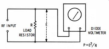
Fig. 6-22. RF wattmeter.
RF power may be measured also with a direct-reading RF wattmeter based on a diode voltmeter and load resistor. This arrangement is shown in Fig. 6-22.
The RF power is developed across noninductive load resistor R which must have a resistance equal to the output impedance of the RF source and a power rating equal to twice the expected power. RMS voltage E is developed across this resistor, and P (in watts ) = E2/R. From this equation, it is seen that the scale of voltmeter M may be made direct-reading in watts only for a particular value of R. This is convenient, however, in cases where power measurements are always made with a single load resistance, such as 50 or 72 ohms.
ANTENNA IMPEDANCE BRIDGE
Fig. 6-23 shows the circuit of an RF impedance bridge suitable for measuring the impedance of amateur and citizens' band antennas, transmission lines, and other components between 20 and 600 ohms at frequencies up to 50 mc. After the instrument is calibrated, the impedance in ohms may be read directly from the dial of variable capacitor C2 which is the bridge balance control. The null indicator is a diode RF voltmeter consisting of a miniature lN55AS germanium diode (X) , resistors R2 and R3, RF choke RFC, and bypass capacitor C3.

Fig. 6-23. RF impedance bridge.
One leg of the bridge is composed of C1 and C2, the other of R4 and the unknown impedance (Z) connected to coaxial jack J2. The RF input signal is injected via coaxial jack J1.
At the balance (null ) setting of C1, meter M reads zero, and the unknown impedance Z = (C2R4) /C1. Rheostat R3 is a variable voltmeter multiplier which acts as a sensitivity control, permitting meter M to be set for best sensitivity with a given input-signal amplitude. Since M is used only as a null indicator, the actual reading of this meter is unimportant.
The simplest way to calibrate the instrument is to adjust the bridge for null separately with as many noninductive resistors as obtainable connected successively to J2 with short leads, and to inscribe the C2 dial with these resistance values.
Thus;
1. With the RF signal injected via J1, connect a 20-ohm resistor to J2.
2. Adjust C2 for null, setting R3 for maximum sensitivity as null is approached.
3. At null, mark the C2 dial 20.
4. Repeat with other resistance values at J2, marking the C2 dial accordingly.
Use of the instrument is equally simple;
1. Inject the RF test signal via J1.
2. Connect the antenna, transmission line, or other unknown impedance to J2.
3. Adjust C2 for null, adjusting R3 for maximum sensitivity as null is approached.
4. At null, read the unknown impedance from the dial of C2.
AMPLITUDE MODULATOR
Fig. 6-24 shows a circuit for amplitude modulation of a radio-frequency carrier with an AF voltage. A modulator of this type may be built into an oscillator or signal generator or may be used externally. The circuit utilizes the ability of the diode, as a nonlinear resistance, to generate modulation products of two signals presented to it simultaneously.
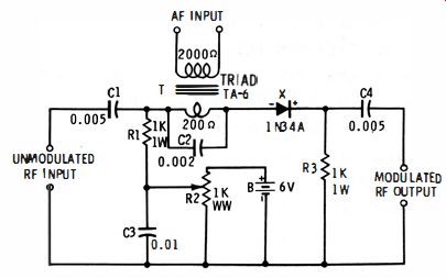
Fig. 6-24. Amplitude modulator.
The unmodulated RF is coupled into the circuit through C1 and R1 (that portion of R2 in the circuit is RF-bypassed by C3 ). The AF is introduced through miniature transformer T the secondary of which is RF-bypassed by C2. Modulated RF is developed across R3 and coupled to the output through C4.
The diode is forward-biased into its most favorable conduction region by means of DC from battery B and potentiometer R2. This adjustment is made by setting R2 while observing the output AM signal with an oscilloscope connected to the MODULATED RF OUTPUT terminals. Set R2 for best linearity of modulation, and the AF input amplitude for desired modulation percentage. The bias voltage may also be obtained from a well-filtered DC power supply.
AM PHONE MONITOR
Modulation quality of an AM transmitter may be aurally appraised with a simple linear diode detector. It is not necessary to tune the circuit to the carrier frequency.
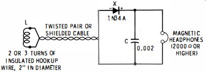
Fig. 6-25. AM phone monitor.
Fig. 6-25 shows the circuit of this type of monitor. The modulated signal is picked up by coupling coil L which is placed near the transmitter tank. Except with very-low powered transmitters, the signal amplitude will be high enough to operate the IN34A germanium diode (X) in its linear region, so that little distortion will be generated by the circuit.
High-resistance magnetic headphones must be used. If crystal headphones are used, connect a 2,000-ohm 1/2-watt resistor in parallel with them.
SQUARE-WAVE ADAPTOR
A 2-diode limiter or clipper circuit may be used to convert sine waves into clipped waves which are essentially square.
Such a circuit is shown in Fig. 3-1, Section 3. The higher the amplitude of the sine-wave input voltage, the steeper will be the sides of the output wave.
A similar adaptor which requires no DC bias is the double anode zener diode regulator shown in Fig. 4-3B, Section 4.
Because of the relatively high zener current of 12 ma, this adaptor requires more driving power than the one mentioned in the preceding paragraph.
Simple adaptors of the limiter-clipper type operate satisfactorily up to 50 or 100 khz. At higher frequencies, diode capacitance, stray capacitance, and diode recovery time combine to distort the square wave.
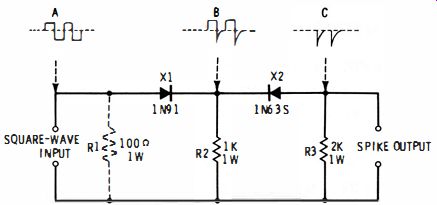
Fig. 6-26. Timing marker (spike) generator.
TIMING-MARKER (SPIKE) GENERATOR
Fig. 6-26 shows the circuit of a simple adaptor for obtaining sharply spiked pulses from a square-wave input signal.
Such spikes may be used as timing markers on an oscilloscope screen, for synchronizing control and counting circuits and time-base generators, and for special-purpose modulation. Unlike RC circuits which also form pulses from a square wave, this circuit is not frequency-sensitive.
Operation of the circuit is based upon the slow reverse recovery time of the lN9l germanium diode ( X1). The output of X1 is shown by pattern B. Note from this pattern that X1 passes the positive half-cycles of square-wave input voltage but does not immediately shut off when the negative half-cycle appears. Instead, the few current carriers left at the X1 junction after the forward conduction give this diode a momentary low back resistance, resulting in the initial high-amplitude negative spike current. This current in turn sets up a voltage across R2 which has the same spiked shape. The lN63S germanium diode then rectifies this voltage, stripping off the square positive half-cycles and passing only the spikes, as shown by Pattern C. This current develops a voltage drop having the same spiked shape across output resistor R3. Output-spike amplitude may be varied by adjustment of the output of the square-wave generator.
Resistor R1 is required only if the output circuit of the square-wave generator provides no low-resistance DC return path for X1.
HARMONIC INTENSI FIER FOR FREQUENCY STANDARDS
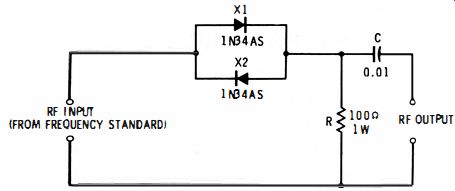
Fig. 6-27. Harmonic intensifier.
The higher harmonics from a secondary frequency standard such as a 100-khz tube or transistor oscillator often are too weak for use. A harmonic amplifier stage sometimes is added to accentuate these harmonics.
Where use of such an amplifier is inconvenient, a good amount of harmonic intensification may be obtained by distorting the output waveform of the frequency standard with semiconductor diodes. Fig. 6-27 shows one type of intensifier circuit. Here, two lN34AS miniature germanium diodes ( X1, X2) are connected back-to-back to handle the entire RF wave.
( X1 passes forward current during the positive half-cycle, and X2 during the negative half-cycle.) The distorted current pulses set up an output-signal voltage drop across 100-ohm resistor R. For best results, the signal applied to the circuit should have a minimum amplitude of 0.1 volt rms, and for safety to the diodes the signal should not exceed 4 volts rms.
NOISE GENERATOR
The broad-band noise signal is increasingly in demand for testing receivers, amplifiers, and other electronic equipment.
An inexpensive noise generator can make use of the noise factor of a reverse-biased silicon point-contact diode.
Fig. 6-28 shows the circuit of a diode noise generator of this type. In this arrangement, a lN2lB silicon point-contact diode (X) , is reverse-biased to a maximum of 6 volts by battery B through 50,000-ohm rheostat R1. The reverse current flows through 300-ohm output resistor R2 and sets up the output noise voltage drop across this resistor. Note that germanium diodes are unsatisfactory for this application.
The noise output voltage is maximum at high current ; that is, when R1 is set to zero (or minimum) resistance. This rheostat thus functions as a noise-voltage amplitude control.
This simple generator is useful in testing equipment throughout the frequency spectrum from audio up to several thousand megacycles.
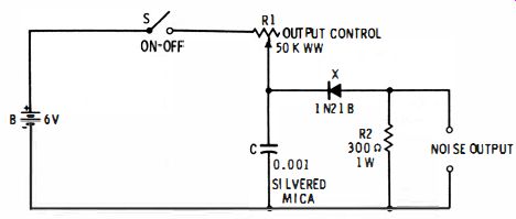
Fig. 6-28. Noise generator.
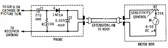
Fig. 6-29. TV antenna compass.
TV ANTENNA COMPASS
Fig. 6-29 gives the circuit of a small-sized instrument which may be used as a signal strength indicator during the orientation of a TV receiving antenna. Meter M reads maximum when the antenna is correctly positioned with respect to the transmitting station. This "compass" is operated directly from the TV receiver.
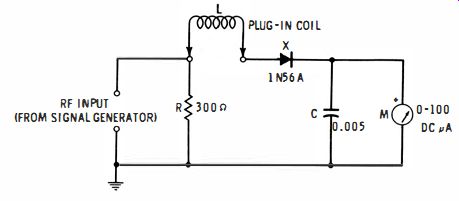
Fig. 6-30. Grid-dip adaptor.
The instrument is divided into two parts; a probe which is connected to the receiver, and a meter box which is taken to the roof. These two units are connected together by means of a plug-in extension cord. The probe is connected to receiver ground and either the grid or cathode of the picture tube (whichever receives the video channel output), and the receiver is tuned to the station of interest. The 1N70A germanium diode (X) rectifies the video signal, and the resulting direct current deflects the remote 0-50 DC microammeter (M) . Rheostat R2 serves as a sensitivity control, and blocking capacitor C1 protects the diode and meter from DC voltages present in the receiver. The operating procedure is straight forward ; orient the antenna for maximum swing of meter M, adjusting R2 as required.
CAUTION: When this instrument is connected to ground (B-minus) of a transformer less receiver, one lead of the extension line and the meter box unit may be at power-line potential. This is a serious shock hazard. For maximum safety; operate the TV receiver from an isolating transformer.
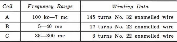
Table 6-2. Grid-dip Adaptor Coil Data
GRID-DIP ADAPTOR
The adaptor circuit shown in Fig. 6-30 permits use of an RF signal generator as a grid-dip oscillator. Tuning is done entirely with the signal generator, and the resonant frequency is read from its dial. The adaptor covers the frequency range 100 khz to 300 mhz in three plug-in coil bands: 100 to 7,000 khz, 5 to 40 mc, and 35 to 300 mc. This circuit is derived from the original design by D.H. Carpenter.
Table 6-2 gives winding instructions for the plug-in coils (L) . All coils are wound on 3f4"-diameter plug-in plastic forms (Amphenol 24-6H). To use the adaptor, plug-in the appropriate coil, L, and connect the adaptor to an RF signal generator, either modulated or unmodulated. Set the generator output for full-scale deflection of meter M. Then couple L to the circuit under test, and tune the generator for dip in deflection of M. At this point, read the resonant frequency from the generator dial.
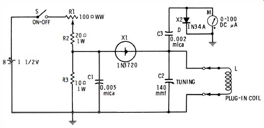
Fig. 6-31. Tunnel diode dip-meter.
TUNNEL DIODE DIP-METER
The simplicity of a tunnel diode oscillator circuit and the small size of the components (including a 1"-diameter DC meter) greatly reduce the size and weight of a grid-dip oscillator. Fig. 6-31 shows the circuit of a tunnel diode dip-meter operated from a single 1.5 volt flashlight cell. This instrument covers the frequency range 1.1 mhz to 150 mhz in four plug-in coil ranges: 1.1-3.8 mhz, 3.7-12.5 mhz, 12-39 mc, and 37-150 mhz.
Table 6-3 gives winding data for plug-in coils (L) . The series-type negative-resistance oscillator uses a 1N3720 tunnel diode ( X1) . DC bias is furnished by the single 1.5 volt, Size-D flashlight cell (B) . Tuning is by means of a 140-mmf midget variable capacitor (C2) and plug-in coil (L) . A portion of the RF voltage developed across the LC2 tank is coupled by C3 to the indicator composed of 1N34A germanium diode X2 and 0-100 DC microammeter M.
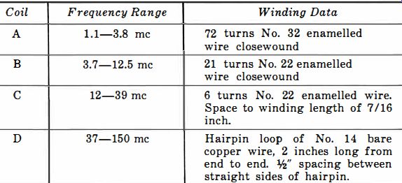
Table 6-3. Tunnel Diode Dip-meter
Coil Data -------- Coils A, B, and C wound on outside of 1"-diameter 4-pin plug-in forms (National XR-1) . Coil D mounted inside same type of form.
To operate the instrument, plug-in a coil and close switch S. Adjust rheostat R1 for strongest oscillation, as indicated by maximum deflection of meter M, then couple L to the circuit under test and use the instrument in the usual manner of a grid-dip oscillator.