AMAZON multi-meters discounts AMAZON oscilloscope discounts
Diode experimenting goes on constantly. As might well be expected, the electrical characteristics of this simple component stimulate thinking about new applications. Many of the new circuits which result from this activity, however, are laboratory curiosities only (a sizeable number were left out of this guide because of their marginal operation ). But others give promise of reliable operation after a reasonable amount of improvement: The circuits presented in this section will be of interest to the experimenter. Often, it is hoped, the published circuit will point the way to some other application when it is not itself directly usable by the reader.
VARACTOR DIODE TUNED CIRCUIT
Small, inexpensive varactors, such as the Varicap, are convenient for tuning an RF circuit by means of an adjustable DC voltage. The tuning voltage reverse-biases the varactor.
Fig. 8-1A shows a typical circuit. The capacitance of the V56 Varicap is varied from 32 to 145 mmf by varying the bias from zero to 15 volts. The bias is applied in series with a 1-megohm resistor (R) which acts both as an isolator and RF choke. Since the V56 draws virtually no current for its operation, no voltage is lost across the resistor. The 0.01-mfd DC-blocking capacitor (C) prevents coil L from short-circuiting the DC bias. The reactance of this capacitor is so low that the varactor is the tuning element.
(B) Response.
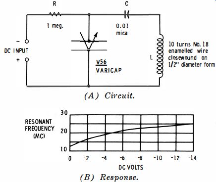
Fig. 8-1 . Varactor tuned circuit.
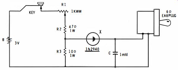
Fig. 8-2. Tunnel diode code-practice oscillator.
The coil specified here covers the range 12 to 25 mhz as the DC is varied from zero to -14 volts. Fig. 8-1B shows this response. Other inductance values will tune over other ranges.
RF energy may be coupled into the tuned circuit by means of a small link coil, or through a 100-mmf capacitor connected to the junction of C and L. The peak amplitude of the RF voltage across D should not exceed 0.1 volt, otherwise it will vary the varactor capacitance.
TUNNEL DIODE CODE-PRACTICE OSCILLATOR
The code-practice oscillator shown schematically in Fig. 8-2 can be built as small as a shirt-pocket hearing aid. It is a keyed audio oscillator using a 1N2940 germanium tunnel diode (X) . The tone-determining tuned circuit is comprised of capacitor C and the inductance of the earphone. The frequency is approximately 2,000 HZ when C is 1 mfd. This may be lowered by decreasing C, and vice versa.
To prevent upsetting the negative resistance of the diode, the earphone must have low DC resistance and low impedance.
Thus, a 6-ohm earplug type unit is shown. A pair of low-impedance headphones also might be used.
To place into operation, close the key and adjust R1 for strongest oscillation. Operate key slowly several times to in sure that oscillator starts readily, readjusting R1 if starting is sluggish.
DIODE AS SOLAR CELL REGULATOR
Silicon solar cells are practical for light-powering transistorized equipment and short-distance telephones, but the DC output of these cells varies widely under differing conditions of illumination.
A 1N34A germanium diode, forward-connected across a silicon cell, will reduce the swing during bright illumination, tending to stabilize the DC output (Fig. 8-3) . The underlying mechanism is the voltage-dependent forward resistance of the diode. This resistance decreases as the photocell output voltage increases, thus loading the cell more heavily at the high voltages and pulling the voltage down.
A 1N34A diode holds the output of an International Rectifier Corp. Type SlM cell at approximately 0.25 volt, 10 ma under widely varying bright-light conditions.
DC TRANSFORMER

Fig. 8-3. Diode as solar cell regulator.
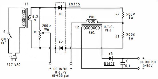
Fig. 8-4. DC transformer.
The circuit shown in Fig. 8-4 accepts a DC input of 0-1.5 volts and delivers a DC output of 0-30 volts into a high-resistance load. It is called a DC transformer because it seemingly steps up the DC input signal through transformer T2. From its operation, this circuit may be considered a DC voltage amplifier ; but it provides no current amplification or power amplification, so it is effective only when operating into a high resistance device, such as a DC VTVM or DC oscilloscope.
Providing, as it does, a step-up ratio of 20, it is often used to amplify small DC voltages for reading on the 0-1.5-volt scale of a VTVM.
The circuit is a balanced modulator, nulled by adjustment of potentiometer R1. The excitation is 6.3 volts AC supplied by the filament transformer, T1. The modulator diodes ( X1, X2) are the units of a lN35S matched-diode assembly. When the circuit is completely nulled, no AC voltage appears at the DC INPUT terminals and no voltage appears at the DC OUTPUT terminals. When a voltage is applied to the DC INPUT terminals, forward current flowing through X1 unbalances the circuit proportional to the applied DC voltage, and AC passes through the primary of transformer T2. This voltage is stepped up by the transformer and rectified by the ' Dl607 high conductance gold-bonded diode (X3). Output capacitor C is charged to the peak value of this voltage. The load connected to the DC OUTPUT terminals must be 1 megohm or higher.
To adjust the device;
1. Plug into AC power line.
2. Connect a DC VTVM to the DC OUTPUT terminals.
3. Close switch S.
4. With no connection to the DC INPUT terminals, adjust R1 for null. If zero cannot be reached as a null, the diodes should be more closely matched.
5. Apply a signal of 1.5 volts in the polarity shown to the DC INPUT terminals. The VTVM should deflect to 30 volts.