AMAZON multi-meters discounts AMAZON oscilloscope discounts
Introduction
The chief application of metallic type, power rectifiers is the conversion of alternating current into direct current for any useful direct current operated device or process requiring a substantial amount of DC power. For this use power rectifiers require only the rectifying property of the metallic rectifier assembly. The DC output ratings of such structures range from a few volts up to several hundred volts and from an ampere up to several thousand amperes. The power rectifier assembly generally contains cooling fins and the assembly may use natural convection or forced air cooling; some times the rectifier assembly may even be immersed in an oil bath cooling system.
In power rectifier application we usually associate the metallic rectifier with its AC line coupling transformer, output control means, switch gear, and, perhaps, a metering system.
Moreover, we often think of these systems as low voltage systems--operating at outputs of a few volts. In truth, how ever, metallic rectifier power installations often become quite elaborate and can supply much larger output voltages at substantial power. For example, the photographs of Figs. 10-1, 10-2, 10-3, and 10-4 show some details of a particularly well engineered rectifier system. Fig. 10-1 illustrates one of the three parts combined to form the DC rectifier system shown in Fig. 10-2. This system of Fig. 10-2 has a continuous DC capacity of 1200 amperes at 125 volts. It has been installed at the H. J. Heinz Co. of Pittsburg as a source of power for elevator motors. The photographs of Figs. 10-3 and 10-4 are close-ups of some of the supervisory and automatic devices incorporated in this equipment which employs selenium rectifier stacks. The rear view of this equipment, also showing the rectifier stacks, may be viewed in the frontispiece photograph of this guide.
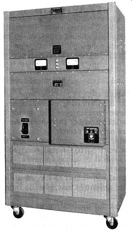
Fig. 10-1. A Front Cabinet View of a Selenium Power Rectifier System. (Courtesy
of W. Green Electric Company.)
Power applications in which metallic rectifiers are employed are so numerous and cover so broad a range of electrical engineering in the DC field that a complete discussion is not only impossible, but, not necessary because it is self evident. However, several power applications have proven very popular and their discussion should adequately cover this type of application for metallic rectifiers. These popular applications for power rectifiers are as follows:
a. Storage battery eliminators.
b. Storage battery chargers.
c. Rectifier supply for electroplating.
d. Rectifier supply for DC motor operation.
e. Rectifier supply for automotive use.
f. Cathodic protection against corrosion.
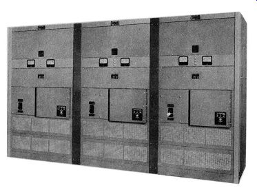
Fig. 10-2. A Selenium Power Rectifier System Using Three of the Units Shown
In Fig. 10-1. (Courtesy of W. Green Electric Company.)
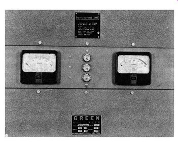
Fig. 10-3. Front View of Supervisory Controls on Rectifier System Shown
In Figs. 10-1 and 10-2. (Courtesy of W. Green Electric Company.)
Storage Battery Eliminator
There are many DC applications wherein the use of a metallic rectifier assembly of the power type can eliminate the troublesome storage battery if a source of AC power is conveniently nearby. Fig. 10-5 gives an example of a battery eliminator for use on private telephone systems, signaling equipment, hospital signal systems, or fire alarm systems.
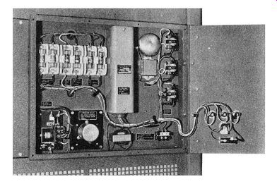
Fig. 10-4. Interior View of Supervisory and Automatic Controls On Rectifier
System Shown In Figs. 10-1 and 10-2. (Courtesy of W. Green Electric Company.)
The AC voltage from the power line is reduced in potential to the required level by means of the step-down transformer T, which also serves to isolate the DC equipment from the AC line by virtue of the inductively coupled primary and secondary transformer coils. The secondary of the step-down transformer is connected to the AC terminals of the full-wave rectifier. This rectifier may be of the magnesium-copper sulfide type, if low output voltage and heavy current are required or of the selenium or copper-oxide type, if moderate currents and low to medium values of DC output voltage are needed. The DC output of the bridge rectifier is in turn wired to a filter circuit consisting of a filter choke and two large electrolytic capacitors. Thus, the output terminals of the battery eliminator provide well filtered DC power, isolated from the power line and having an output voltage and current capacity pre determined by design.
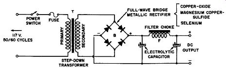
Fig. 10-5. A Storage Battery Eliminator Circuit.
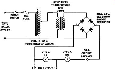
Fig. 10-6. A Battery Eliminator Circuit With a Variable DC Output Voltage
of 0 to 10 Volts, Current Capacity, 50 Amperes.
The circuit design of Fig. 10-6 has an additional refinement permitting a control over the output voltage from zero to the maximum desired value. This control is accomplished without the use of rheostats or potential dividing resistances which are wasteful of electrical power, heat generating, and are one of the causes of poor voltage regulation in the power supply. This source of variable DC output voltage which possesses high efficiency and good regulation is attained by means of a variable auto-transformer of the Powerstat or Variac type connected between the AC source and the primary of the step down transformer as shown. In this way the input to the rectifier system may be varied from 0 to 135 volts in an efficient and continuous manner. Since the control device is a variable auto-transformer, no wasteful heat is generated and the regulation of the system is good from zero to full load. Typical circuit values are given for a system which can provide an output of 0 to 10 volts at 50 amperes DC. The filter circuit can be added to the output terminals shown if a smoother out put voltage is required.
Storage Battery Charging
Storage battery charging is another interesting and profitable application for power rectifiers of the metallic type.
For this application a heavy current output at low voltage (6, 12, or 24 volts DC) is needed. A basic battery charging circuit using a magnesium-copper sulfide rectifier is given in Fig. 10-7. The primary power is derived from an AC source such as a convenience outlet of a lighting circuit at 117 volts, AC.
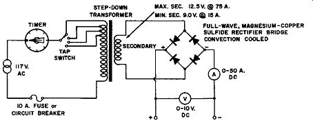
Fig. 10-7. The Basic Battery Charging Circuit, Low Amperage, Convection
Cooling.
The timer in the primary circuit predetermines the length of the charge while the tapped primary permits adjusting the charging rate. The basic circuit gives values for components which are suitable for a low amperage, convection cooled type of installation.
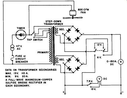
Fig. 10-8. A More Elaborate Battery Charging Circuit.
The circuit shown in Fig. 10-8 is an elaborate version of a storage battery charger; besides having all of the features of the previous basic model, it has a switching system in the output circuit to permit charging either 6 or 12 volt batteries.
At 6 volts the circuit's capacity is 150 amperes; at 12 volts the current capacity is 75 amperes. For this installation forced air cooling is necessary in order to maintain the rectifier operating temperature within safe limits. The electric fan is rated at 800 cubic feet per minute.
TABLE FOR LEAD-ACID TYPE STORAGE BATTERY DC CHARGING RATE CONTROLLED BY PRIMARY TRANS. TAPS. MAX. DC CURRENT BASED ON 2.35 VOLTS PER CELL PLUS I VOLT DROP IN CONNECTING LEADS. MIN. DC CURRENT BASED ON 2.2 VOLTS PER CELL PLUS 1 VOLT DROP IN CONNECTING LEADS.
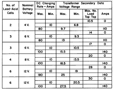
Fig. 10-9. Charging Rate Table With Transformer Secondary Data.
An interesting storage battery charging table is given in Fig. 10-9 correlating the battery voltage against maximum and minimum charging rate and the required transformer secondary data. This design data is intended for use with the magnesium-copper sulfide type rectifiers.
DC Supply for Electroplating
The use of metallic rectifiers in DC power supplies for electroplating, electro-cleaning, and anodizing was somewhat new before World War II, but "three-shift" operation during the war and their expanded usage after has firmly established them a place in this field.
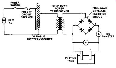
Fig. 10-10. A Single-Phase, Full-Wave Electroplating Circuit.
For this electro-finishing application the single-phase, full-wave rectification circuit of Fig. 10-10 is satisfactory for small jobs. It simply involves a means to control the output (the variable autotransformer), a power transformer to reduce the line voltage down to the required lower voltage, a full-wave metallic rectifier, and an ammeter and voltmeter to measure the DC output. Such an arrangement can be compact, noiseless, and simple to use. A portable unit can easily have a rated output of 6 volts at 25 amperes, DC. Other single-phase electro-plating power units are being manufactured with current capacities of up to 150 amperes at 6 volts and with reduced current ratings at the higher voltages of 12, 18, 24, and 48 volts.
Single-phase, full-wave rectification power units are satisfactory for most electroplating, cleaning, and anodizing; often in hard chrome plating which usually requires high current densities and less AC ripple in the output, three-phase type power rectifier circuits are used. Electro-plating rectifiers with DC output ratings over one kilowatt are also manufactured in the three-phase design so as to attain efficient and balanced connection to the factory three-phase power supply of 220, 440, or 550 volts AC. Fig.10-11A shows the diagram of the three-phase, half wave rectification circuit; and Fig. 10-llB the three-phase bridge circuit. Louis W. Reinkin, chief engineer of W. Green Electric co., N. Y. in his series of articles entitled "Rectifiers for Electro-plating", starting with the February, 1947, issue of the magazine "Metal Finishing"*, stresses a good point when he states that he prefers to call the circuit of Fig. 10-llA a three-phase star circuit rather than a three-phase, half-wave rectification circuit. His reason for this preference is that it is common to associate poor efficiency and performance with half-wave circuits of the single-phase type. A three-phase star circuit (three-phase, half-wave) is entirely satisfactory for electro-finishing and is considerably more efficient than a single-phase full-wave bridge circuit. The three-phase bridge circuit of Fig. 10-11B requires six rectifier arms in place of the three half-wave assemblies of the star circuit of Fig. 10-llA for the same output current, but twice the output voltage of the star circuit can be obtained.
(A) Three-Phase, Half-Wave or "Star" Circuit. (B) Three-Phase Bridge Circuit.
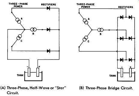
Fig. 10-11. Three-Phase Electro-finishing Circuits.
In three-phase applications of the metallic rectifier, either circuit of Fig. 10-11 is satisfactory for electro-finishing and the final choice is dependent upon the rectifier type selected and the DC output voltage required.
If the plating power supply uses copper-oxide or magnesium-copper sulfide type rectifiers, the three-phase bridge circuit is commonly employed because the lower voltage ratings of these rectifiers make it necessary to use the same total number of rectifier plates for the star circuit and the star transformer is more expensive to build. When selenium rectifiers are employed for the plating power plant, their higher voltage ratings per plate (26 volts rms) permit the efficient application of the star circuit for DC outputs up to 6 to 8 volts, since the bridge type circuit requires twice as many plates and would be less efficient than the star circuit. Above 8 volts DC output the desirable choice for any type of rectifier is the bridge circuit.
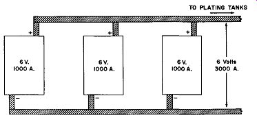
Fig. 10-12. Method of Paralleling Rectifiers for Greater Current Capacity.
Power rectifier assemblies for electro-finishing are available in a wide variety of voltage ratings and current capacities; the 6 volt rating is the most widely used. At this voltage rating units are available with current capacities from 1000 to 5000 amperes. Higher current capacities may be obtained by connecting two or more of these rectifier power supplies in parallel. Fig.10-12 illustrates the proper polarities to observe when paralleling rectifier units and applies for a system having an output rated at 6 volts, 3000 amperes DC, obtained from three unit assemblies rated individually at 6 volts, 1000 amperes DC.
The series connection of two or more identically rated rectifier power supplies is useful when an output voltage higher than the rating for the individual unit is required. For example, if a DC output of 18 volts at 1000 amperes were necessary, this could be secured by connecting the three power units of Fig. 10-12 in series in the conventional fashion of positive terminal to negative terminal and so on. Series connected rectifiers are particularly useful for anodizing where the final operating voltage for the process is required to range between 40 and 48 volts.
Electro-finishing equipment has to be carefully designed to protect the operator from electrical shock hazards and the power supply components from the corrosive liquids and atmosphere common to such operations. The installations can become somewhat elaborate too, with the switch gearing, meters and the automatic controls. Electric timing meters, which are preset by experience, may be employed for timing the electro-finishing process or amperehour controls may be used which shut off the plating current after a predetermined quantity of amperehours has elapsed rather than an arbitrary time interval. Amperehour control is more desirable for if the voltage, bath temperature, and bath composition are maintained reasonably constant, then the plating thickness can be closely controlled by the setting of the amperehour meter.
Power Supply for DC Motor Application
There are many fields of application for an adjustable speed motor. Although it might appear that this need could be fulfilled by means of a variable autotransformer of the Variac or Powerstat type feeding an AC motor of the series or repulsion type, experience has proven that this arrangement while satisfactory at constant loading will produce wide changes in speed under varying load.
DC motors, particularly the DC shunt or compound type, provide better speed regulation and wider speed range as adjustable or variable speed drives. The problem then is a DC power supply to drive the shunt or compound motor. Again the metallic rectifier lends a hand with the help of the variable autotransformer to facilitate an economical answer to the problem described above. In these arrangements of variable speed motors an adjustable autotransformer of the Variac or Power stat type feeds a full-wave rectifier bridge to supply thereby a variable armature voltage of 0 to about 125 volts DC to a DC shunt or compound motor. The field of this motor is usually maintained at a constant value with full excitation over the speed range. Sometimes, this field excitation may be reduced to a lower constant value to provide another and higher speed range. Such a system as described provides a speed range of 15 to 1 to as much as 50 to 1. The commercially available variable speed power units fulfilling this system control motors up to 1/3 horsepower and are compact enough to be conveniently installed on the bench near the device to be operated by the variable speed motor.
Applications for which this type of motor controls are especially suitable are: coil winding machines, small lathes, drill presses, and other light machine tools where easily con trolled shaft speeds are a requirement or a convenience.
Where timing of an operation must be adjustable over a wide range as in electroplating, blue printing machines, and photo graphic developing; this type of motor control is suitable. In variable speed systems where the load is practically constant, the motor speed will be maintained very close even for small line voltage variations. The reason for this is that in a shunt motor the change in the field excitation partly compensates the armature variation.
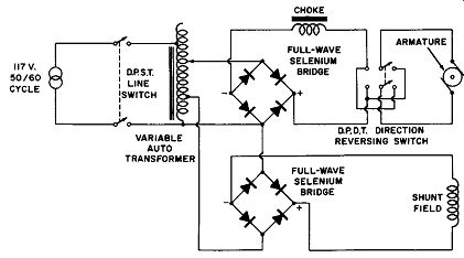
Fig. 10-13. A Speed Control Circuit for a DC Motor Fed From an AC Source.
Fig. 10-13 shows the circuit connections for a metallic rectifier speed control suitable to power a DC shunt or compound motor. You will note that separate full-wave bridge rectifiers are used to supply the armature and shunt field independently. In this way the armature voltage may be varied from O to about 125 volts DC, while the shunt field voltage is kept constant over the speed control range. The double-pole double-throw switch provides a means to reverse the direction of rotation of the motor armature while the choke in series with the armature serves to maintain a low ripple current in the armature circuit as well as improve the speed regulation.
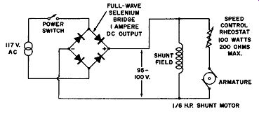
Fig. 10-14. A Simple Variable-Speed Drive Circuit.
A simpler circuit for controlling the speed of a DC motor retains most of the previous advantages but its speed range and regulation are impaired somewhat. It is more economical of rectifier bridges and does not use a variable autotransformer but a less expensive rheostat. This circuit is shown in Fig. 10-14 and has been successfully employed with shunt motors of 1/6 horsepower over a speed range of 5 to 1 without compensation for the voltage loss through the full-wave rectifier bridge. The full-wave rectifier is rated at 135 volts rms maximum. At 117 volts rms it has a DC output of 100 volts at 1 ampere. In continuous application both the motor and the rectifier run cold at any position of the speed control.
Rectifier Supply for Automotive Use
This application does not fulfill the statement in the introduction of this Section--that of being a current popular use for power rectifiers of the metallic type, but it is likely to prove an important factor in the automotive field in the near future. It is well known that all of the electrical equipment on automotive vehicles is powered from the storage battery and DC generator; the generator also serves to maintain the battery's charge. Recently the electrical demand upon this battery generator system has increased so greatly that it is becoming more difficult to design economical DC generators which can handle the needs of the new electrical accessories mounted upon the vehicles. The commutator and brushes of the DC generator are especially expensive to build--along with the increased maintenance problems.
The idea being tested which involves the metallic rectifier is to use an alternator whose output is rectified by a full-wave bridge type rectifier. This combination offers economical design, less rotating and moving parts to maintain (for there are no brushes and commutators), automatic and better voltage regulation with varying engine rpm, and automatic reverse current protection. In addition, it is feasible to use the AC output directly for such electrical equipment as the radio, lights, electric gauges, heater, and windshield wiper with beneficial results in cost and service.
By careful design of the alternator, it is possible to obtain almost constant voltage output without the troublesome electro-mechanical voltage regulator used with the present DC generator and storage battery combination. This feature alone results in longer electric light life and simple design for the electrical fuel, oil pressure, and engine temperature gauges.
A simplified circuit presenting the basic idea of the full wave metallic rectifier applied in the automotive field is given in Fig. 10-15. This figure is self-explanatory; however, it is to be noted that the rectifier bridge because of its unilateral conductivity acts as a reverse current cut-out relay, since it prevents the storage battery from discharging back into the stator windings.
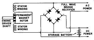
Fig. 10-15. Metallic Rectifier Application In Automotive Vehicles.
Several of the large automotive vehicle manufacturers have been running road tests on cars equipped with metallic rectifier systems similar to that described above and there is a good possibility that this versatile power rectifier may soon invade the automotive field.
Cathodic Protection Against Corrosion
The last application of metallic rectifiers of the power type to be discussed in this section is cathodic protection against corrosion. This is the protection of metallic structures which have to be buried in soils or immersed in water, for example, oil and gas pipe lines, bottoms of metal storage tanks, lead sheathed cables for telephone and electric power work, water tank installations, submerged portions of building structures, and the like.
Any metallic structure buried in soils or immersed in water is subject to corrosion because destructive electric currents which are generated by chemical action between structures and the surrounding electrolytes strip off minute particles of the metal until the buried metallic structure, pipe, steel beam, or metal surface becomes so weakened that it is eventually destroyed. Hence, corrosion of buried or submerged metal is the result of electrical current flowing from the metal into the surrounding soil or water. This current flow carries metal particles of the structure away from it in minute quantities and the result is corrosion or electrolysis. Over a period of time this electrolytic action will result in leaks in pipes or disintegration of metallic structures which have to be buried or submerged. This electrolytic corrosion can be overcome if direct current can be induced to flow from the surrounding soil or water toward the metal pipe or structure being protected instead of away from it. This type of protection is called cathodic protection and involves the flow of direct current through the soil or water to the entire exterior of the structure or a current flow direction opposite to that of the corroding current.
For this type of protection a continuous and economical source of DC is required; this is easily secured from metallic rectifiers, particularly of the selenium type. Usually, the installations for this type of service operate at a voltage of 2 to 12 volts and at a current capacity of from 10 to 1000 amperes depending upon the surface area to be protected.
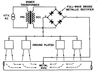
Fig. 10-16. Cathodic Protection of Buried Metal Pipe.
Fig. 10-16 illustrates an installation designed to protect a section of metallic pipe buried in the soil and carrying oil, for example. The corrosion of this pipe can be caused by stray or electrolytic DC currents flowing away from this pipe. This galvanic action may be counteracted by making the pipe negative (cathodic). To do this requires an external source of electric potential applied between the pipe and earth, forcing the pipe potential below the earth potential and maintaining it there.
To do this, an AC source is coupled to a power transformer, to the secondary of which is connected a full-wave metallic rectifier. The positive terminal of the rectifier is connected to a number of grounding plates, while the negative terminal is connected to the pipe as shown. Direct current flows from the rectifier to the ground plates buried at a suitable distance from the protected pipe, through the earth to the pipe and back to the rectifier again. This system renders the pipe cathodic to the soil electrolyte and protects it against corrosion.