AMAZON multi-meters discounts AMAZON oscilloscope discounts
Introduction
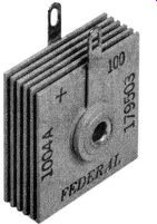
Fig. 11-1. A Small Selenium Power Rectifier. (Courtesy of Federal Telephone
and Radio Corp.)
Small current or power rectifiers have been classified as those having a DC output of one ampere or lower. While these metallic rectifiers can be any one of the three types previously discussed (copper-oxide, magnesium-copper sulfide, or selenium) and of the half-wave or full-wave structure, they are generally designed for single-phase operation. The most popular type employed for applications requiring this current capacity is the selenium. Compactness, lightweight, low cost, and satisfactory voltage rating are the chief reasons for this choice. The photograph of Fig. 9-1 displayed one example of such rectifier assemblies. If the structure is selenium, stock assemblies rated at 130 volts rms maximum, half-wave, single-phase, are easily and economically available from most electronic supply dealers and cover current capacities of 25 to 1000 milliamperes. As an example, the physical size of a 500 milliampere selenium rectifier assembly consisting of a 5 plate structure is 1 1/2 x 3 inches with a stack height of 1 5/16 inches. Fig.11-1 illustrates a single-phase, half-wave selenium rectifier rated at 130 volts rms maximum, with a current capacity of 100 milliamperes DC. It consists of 6 selenium plates assembled upon an insulated bushing with two terminal members so arranged that soldering the rectifier into an application circuit will not damage the active rectifier areas by overheating. The physical size of the plates are 1 x 1 inch and the overall stack height is about 3/ 4 inch. This type of power rectifier is used in great numbers in power supplies for radios, television receivers, amplifiers, and other electrical devices requiring small amounts of DC power. A few examples from some of the more useful applications will illustrate their deserved popularity.
DC Power Supply for Electric Shavers
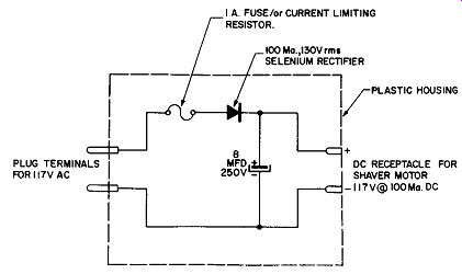
Fig. 11-2. A Selenium Rectifier Power Converter for Electric Shavers.
Most electric shavers use AC to power the internal electric motors which are designed to operate on either AC or DC. If a DC supply were always available these shavers could provide a more smoother, comfortable shave because the speed and performance of the shaver motor can be improved by a factor of as much as 25% by applying DC in place of the usually available AC. Any converter device for this application would have to be inexpensive, compact, and immediately ready for operation upon the application of AC power. The small selenium rectifier has provided a suitable solution to this problem. The shaver converter is available in a compact plastic housing which has means to plug into the convenience outlet of a 117 volt AC supply. A receptacle in this plastic housing is the DC source of power for any AC/DC shaver and about 115 volts at 100 milliamperes of rectified and filtered DC is supplied under load conditions to a typical shaver motor. The circuit is given in Fig. 11-2. As shown in this diagram, the fuse and current limiting resistor may be combined. The purpose of the 8 mfd 250 volt electrolytic capacitor is to provide smooth delivery of DC power over both the conducting and non-conducting half-cycles of the applied input in the manner discussed in Section 9.
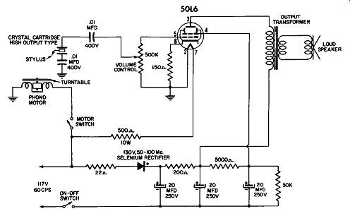
Fig. 11-3. A Phono Amplifier Using a Selenium Rectifier Power Supply.
DC Power Supply for Phonograph Amplifier
Most compact electrical phonographs are designed to contain in a suitable housing about the size of a typewriter case the motor driven turntable, a tone arm carrying a crystal cartridge with its stylus structure, an electronic amplifier, and the loudspeaker. The device is intended for operation on AC because the shaded pole motor used in such applications runs the turntable at approximately the 78 rpm despite line voltage changes of reasonable magnitude. The electronic amplifier, however, even though it may involve only one radio tube, will need DC voltages to polarize and power its electrode elements.
This DC supply should be inexpensive, compact, and efficient so as to minimize heat dissipation within the confined cabinet.
A selenium type small power rectifier will be suitable and a typical diagram of such an application is shown in Fig. 11-3.
The turntable motor is driven by the 117 volts AC input of suitable frequency, usually 60 cycles per second. The electronic amplifier, however, requires DC potentials which are obtained by means of the half-wave selenium rectifier which is rated at 130 volts rms at a current capacity of 50 to 100 milliamperes. The output of the rectifier is well filtered by means of two stages of resistance-capacitance filters to minimize electrical hum in the loudspeaker. This well filtered DC source then powers the elements of the tube which drives the loudspeaker when the electrical signals from the crystal cartridge are applied to the control grid of the tube.
Power Supply for Small Electrical Devices
Frequently, it is necessary to power some DC actuated device when the only convenient power source is the AC line.
----------------------
SELECT SELENIUM RECTIFIER SR WITH ADEQUATE CURRENT RATING FOR DESIRED CURRENT OUTPUT. SELECTION CHART FOR CAPACITOR C ELECTROLYTIC RATED AT 250 V CURRENT OUTPUT DC 250 Mo.
300 Mo.
350 Mo 400 Mo.
REQUIRED C IN MFD 40 50 60 70
------------------------------
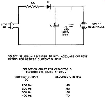
Fig. 11-4. A Selenium Rectifier Power Supply Suitable for Small Electrical
Devices.
Such devices may be small motors, DC electromagnets, relays, and the like. A suitable power conversion device for these applications giving the appropriate circuit constants for a number of current capacities is given by Fig. 11-4. The arrangement uses the familiar half-wave selenium rectifier consisting of a 5 plate assembly and has a DC output rating of about 120 volts.
The 0.01 mfd mica capacitor which is shunted across the DC output terminals is not absolutely necessary for the proper functioning of this power supply, but it does minimize line carried electrical disturbances of impulse or high frequency character which may upset the operation of the DC device powered from this supply. Otherwise, the operation of this circuit is as described in Section 8, under the heading "Single Phase, Half-wave Rectifier with Capacitor". DC Supply for Magnetic Chucks Grinding and polishing machines require magnetic chucks to hold the work pieces in place during these operations. A metallic rectifier system for supplying the DC power necessary has the advantage of simplicity, no waiting time for heater warm-up (as in tube type rectifiers), compactness, and practically zero maintenance. A satisfactory circuit to supply 280 volts at 500 milliamperes DC is diagrammed in Fig. 11-5.
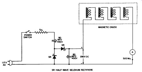
Fig. 11-5. Selenium Rectifier Power Supply for a Magnetic Chuck.
This circuit uses the principle of the voltage doubler scheme previously discussed to secure an output voltage greater than the AC input without the use of step-up transformers.
AC-DC Radio Power Supply
The next application of small power rectifiers of the metallic type to be discussed here involves radio receivers, usually, of the "table" type which are so designed to operate on either an AC or DC supply of 117 volts without switching or relay devices. With this type of universal supply on DC it is only necessary to be sure that the plug on the end of the power cord is inserted into the line receptacle correctly so as to match the positive polarity of the power line with the positive polarity of the plug terminal. No damage is done if the plug is reversed on the first try except that the radio will not operate after the usual warm-up time has elapsed. It is then necessary to "reverse" the plug in the line receptacle to ensure proper operation on the DC supply. The rectifier which is used in this type of circuit serves no useful function on the DC supply. If the same plug is now inserted into an AC receptacle, the AC-DC radio receiver still operates properly and in this case the rectifier and its associated filters are doing the work to make this possible. The circuit is given in Fig. 11-6. The heaters of the four conventional radio tubes used for radio reception are wired in series with a current limiting resistor, and pilot light across the power line when the power switch is actuated.
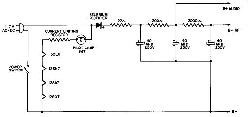
Fig. 11-6. An AC-DC Radio Power Supply Using Selenium Rectifiers.
Television Power Supplies
A power supply commonly used in television receivers is a half-wave, voltage-doubler circuit using two selenium rectifiers. A circuit employing this method is shown in Fig. 11-7. In this circuit, a filament transformer is used to supply one 12.6- and two 6.3-volt sources for tube filaments.
The 5-ohm resistor R1 functions as a current limiter which opposes the initial surge current occurring when capacitor C1 first charges. This resistor also acts as a fuse and protects some of the more expensive components in case a short circuit develops across the output load.
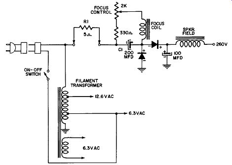
Fig. 11-7. Half-Wave, Voltage-Doubler Circuit Employing Selenium Rectifiers,
Used in Television Power Supplies.
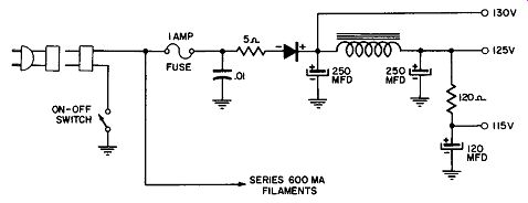
Fig. 11-8. Conventional Half-Wave Rectifier System Using Selenium Rectifiers.
One of the simplest and perhaps the most popular low voltage power supply used in TV receivers is the half-wave rectifier system shown in Fig. 11-8. Somewhat larger values in the filter network are required for a circuit of this design.
The receiver used in this example employs a series filament string; and is typical of the newer chassis designs.
Sarkes Tarzian, Inc. has made available a unit which will enable the service technician to plug selenium rectifiers into a set in the same manner that tubes are inserted. This conversion chassis Model CC-1, together with a pair of typical selenium rectifiers may be seen in Fig. 11-9.
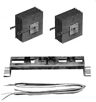
Fig. 11-9. A Pair of Selenium Rectifiers Together with Conversion Chassis
Model CC-1 Made by Sarkes Tarzian, Inc.
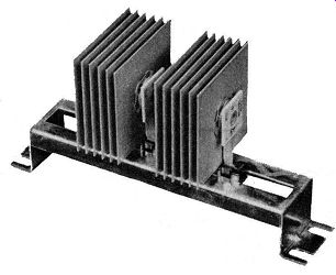
Fig. 11-10. View of Conversion Chassis with Rectifiers In Place.
Fig. 11-10 shows the rectifiers after they have been plugged into the conversion chassis. The only step necessary before the rectifiers can be plugged in is to twist the positive terminal on each rectifier 90 degrees. Twisting the lug in this way ensures that the rectifier will always be in the correct polarity when it is inserted.