AMAZON multi-meters discounts AMAZON oscilloscope discounts
Introduction
The usual type of instrument used in the measurement of voltage and current in alternating current circuits depends upon the moving iron vane principle. In this type of measuring instrument the voltage or current to be indicated energizes a solenoid within the instrument case which in turn reacts upon a pivoted iron vane carrying with it the instrument pointer. Although such instruments are rather accurate (1 to 2%) and are commonly used for measurements in AC circuits, there are three major limitations accompanying their usage: first, considerable power must be "robbed" from the circuit in which it is desired to make the measurement, that is, the instrument sensitivity is poor; second, as compared with the linear scale properties of DC instruments , the scale of commonly used AC instruments is nonlinear and rather crowded at the lower end. Fig. 12-1 shows a comparison of the linear scale of a 0 to 1 volt DC voltmeter to that of an AC voltmeter of the moving vane type covering the same voltage range. The third limitation of commonly used AC measuring instruments is the narrow frequency range; the frequency response of the moving vane type AC meter is limited to a few hundred cycles at most--usually about 125 cycles per second.
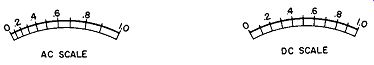
Fig. 12-1. Scale Comparison of AC and DC Meters.
These disadvantages, namely, excessive power consumption, nonlinear scale spread, and limited frequency response may be overcome by using the more sensitive meter movement of the D' Arsonval type equipped with instrument type metallic rectifiers to permit operation on AC circuits.
It is true that the accuracy of this type of AC meter is not as good as that obtained from the moving vane type and that means must be provided for compensation of certain conditions, yet for many electronic and communication circuits, the loading presented by moving vane instruments allows no readings at all or readings in error by several hundred percent. Hence, the 3 to 5% error normally attributed to rectifier meter type of AC instruments becomes quite attractive.
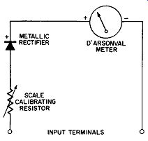
Fig. 12-2. Rectifier Type AC Volt meter.
Fig. 12-2 shows a simple circuit for converting a D' Arsonval meter movement into an AC measuring instrument--in particular an AC voltmeter. The arrangement consists of a calibrating resistor, half-wave metallic rectifier, and a D'Arsonval meter, all connected in series. The rectifier converts the alternating current into pulsating direct current, the moving coil meter indicates the average value of this current, and the calibrating resistor establishes the value of the AC input potential necessary to deflect the meter pointer to full scale.
Using Fig. 12-2 as our pattern for rectifier type AC measuring instruments, we can see that they consist essentially of a device for rectifying the alternating current and a moving coil meter to indicate the value of the rectified direct current supplied by the rectifier. The moving coil meter is a current operated device, commonly a microammeter or milliammeter movement, wherein the deflection of the indicating pointer is proportional to the current flow through the moving coil. Therefore, the sensitivity of the rectifier meter combination is determined by the ratio of the forward to reverse current that the rectifier is capable of producing in the moving coil of the meter. This ratio depends upon the rectifier type selected and upon the circuit in which the rectifier is used.
Some Required Properties of an Instrument Rectifier
The metallic rectifiers used in rectifier type AC meters are called instrument rectifiers; although they operate on the same basic principle of unidirectional conductivity common to all metallic rectifiers, their successful operation for instrumentation purposes requires certain properties not necessarily important in other rectifier applications. The more important of these properties are: no threshold effects, permanence in characteristics ,and high efficiency and stability.
Without getting too involved into the ideal requirements of an instrument rectifier, we know that the above considerations limit our selection of the type to that of the copper-oxide rectifier.
This type metallic rectifier is the only one of the three types previously discussed which does not exhibit some threshold effect, that is, it does not require a critical value of input or applied voltage before current conduction results.
By requiring permanence of characteristics as a property in the desired rectifier for instrument application, we mean minimum "aging" or changes in the electrical properties of the rectifier after it has been applied and calibrated into the meter circuit.
By high efficiency we desire a high ratio of forward to reverse direct current; and by stability we desire minimum changes in rectifier properties due to external effects, such as temperature, atmospheric conditions, and the like.
From our previous study of metallic rectifiers we learned that the process of rectification depended upon the property known as unidirectional or unilateral conductively; moreover, we found that this "unilateral conductivity" is not perfect--that there is always some current flowing through the rectifier in the reverse direction when the applied potential is reversed, as when applied in an AC circuit. Thus, whereas the ideal instrument rectifier should have the volt-ampere characteristics shown in Fig. 12-3A, in practice this characteristic is more nearly like Fig. 12-3B.
The ideal characteristic shows no leakage or reverse direction current flow, no threshold effects, and a linear forward current flow with the applied forward potential. The characteristic of available instrument rectifiers show that as the reverse potential is increased, an increasing amount of leakage current flows and that, although there is no practical threshold effect, if the copper-oxide type of rectifier is used, the forward characteristic is not linear; for equal increments of applied voltage more current flows at higher levels of potentials than for lower levels of potential. The undesirable leakage current of the practical rectifier reduces its efficiency and complicates its application in multi-range instruments. The non-linear forward characteristic makes it more difficult to approach linear AC scales and conformity of scales between ranges of multi-range AC meters; however, both of these effects can be compensated in instrument applications.
(A) Ideal Characteristic. (B) Practical Characteristic.
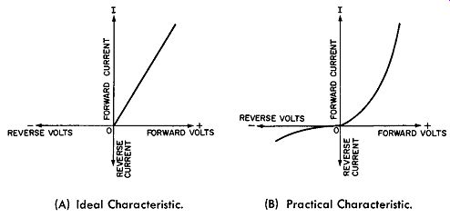
Fig. 12-3. Characteristics of Theoretical and Practical Instrument Rectifiers.
By requiring permanence in the instrument rectifier, we want minimum drift or aging in the rectifier so that the factory calibration of the rectifier meter combination will be retained. Aging in metallic rectifiers can be caused by mechanical damage, chemical action, improper processing during manufacture, or overheating the active areas when soldering the rectifier into the application circuit.
The reader will recall that the unidirectional conductivity of the copper-oxide rectifier is due to the copper-oxide barrier layer; this layer is of a crystalline nature. All crystals are solids and their forms can not be changed by mechanical means without fracturing the crystal. In the crystalline layer which represents the rectifying or barrier junction in the metallic rectifier, any mechanical stresses which cause even slight deformation of the rectifier disc will tend to produce minute cracks in the crystals forming the barrier layer. These minute cracks or fractures in the crystalline layer cause permanent changes in the electrical properties of the rectifier. For this reason, rough handling, subjection to mechanical stresses, or inaccurate dimensions in manufacture, which result in areas of uneven compression upon the assembly of the rectifier discs, are to be minimized in instrument rectifiers if "aging" or permanent changes in the electrical properties of the rectifiers are to be avoided.
Chemical action also causes aging. This chemical action can be the result of incorrect or incomplete processing during the manufacture of the rectifier or due to external chemical action from contamination in the atmosphere. The presence of rubber insulation in the proximity or contact with the rectifier is detrimental too. An adequate lacquer coating is usually sufficient protection against atmospheric contamination but sulfur compounds in the rubber are more difficult to counteract.
Overheating metallic rectifiers when soldering them into circuits can also cause aging or change in its electrical properties. For this reason most instrument rectifiers are provided with flexible, multi-stranded wire leads so as to preclude direct soldering to the rectifier terminals. These flexible leads are soldered to the terminal plates before the rectifier is processed and assembled; in this way direct soldering to the rectifier terminals is avoided for such procedure can cause intense localized heating resulting in uneven expansion of the rectifier discs common to the terminals and thus cracking the crystalline rectifying junctions. This brings about loss of rectifying efficiency and change in the electrical characteristics of the instrument rectifier.
Physical Description of Instrument Rectifiers
Instrument rectifiers are the specialized class of metallic rectifiers having disc areas much smaller than those used for conventional power supply units. The smaller physical size serves three useful purposes. First, the reduced active area provides less shunting capacitance; this helps improve or extend the high frequency response of the rectifier.
Second, the reduced active area increases the current density of the rectifier helping to reduce its forward resistance.
Third, the smaller physical size makes more practical the special processing required in instrument rectifiers to obtain the necessary electrical properties. One such special process is the thin layer of pure gold which is sputtered on the cuprous oxide film and upon the reverse side of the rectifier disc to improve the electrical conduction and to protect the active surfaces.
Sketches of two types of instrument rectifiers are shown in Fig. 12-4. They represent the full-wave bridge structure although instrument rectifier assemblies may also be obtained in half-wave or special combinations of rectifier discs. In the rectifier shown in Fig. 12-4A the disc diameter is about 1/2 inch and the active area of each disc is about0.15 square inch.
Usually 2 to 3 inches of braided, tinned, copper leads are furnished already soldered to the cell terminals. Nickel plated end plates and an insulated machine screw hold the assembly together. The whole assembly is coated with one or more layers of clear lacquer as a protection against atmospheric conditions. In a conventional bridge arrangement such an instrument rectifier has a continuous electrical rating of 5 to 10 volts rms input and a DC output current of 30 milliamperes. This type of rectifier is suitable for the operation of less sensitive or more robust meter movements, relays, and other electrical devices requiring more than one milli ampere of rectified output. It is also suitable for all commercial and lower audio frequency applications and will operate up to 50,000 cycles per second in arrangements where the accuracy of the meter reading is not important.
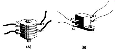
Fig. 12-4. Instrument Rectifiers.
The instrument rectifier shown in Fig. 12-4B has a disc diameter of approximately 0.15 inches and an active area of 0.02 square inches. This rectifier is also furnished with 2 to 3 inches of stranded, tinned, copper leads. The assembly structure is not evident because it is sealed in a moisture proof compound. This type rectifier is suitable for extended frequency range with a meter, relay, or other device requiring less than one milliampere of current for operation. With special circuitry and care, frequency response up to 15,000,000 cycles per second can be attained with the type rectifier shown in Fig. 12-4B. Its normal continuous electrical rating is 2 to 5 volts rms input and it can supply up to 5 milliamperes output current.
The Half-Wave Instrument Rectifier Circuit
The simple circuit of Fig. 12-2, which illustrates the application of a half-wave instrument rectifier to a moving coil DC meter along with the calibrating resistor to provide us with a rectifier-type AC voltmeter, will serve if we are not too critical of the linearity of the instrument scale and if we do not propose to make it into a multi-range instrument as shown in Fig. 12-5. For example, suppose we wish to construct a two range, rectifier-type AC voltmeter patterned after Fig. 12-5 and covering the full scale ranges of 5 and 100 volts rms. Having selected a suitable half-wave copper oxide rectifier and a 0 to 1 DC milliammeter it is first necessary for us to decide upon the value of the series multiplier resistor to be used in the 5 volt range. If the input were 5 volts DC and we did not use the rectifier, we would know at once that the multiplier resistor should be 5000 ohms. How would we know this? For an input of 5 volts DC we desire a full scale indication of the milliammeter pointer (which re quires 1 milliampere). The multiplier resistance R, equals E/1 or 5 volts divided by 0.001 ampere or 5000 ohms, the proper value for the multiplier resistance for the low range.
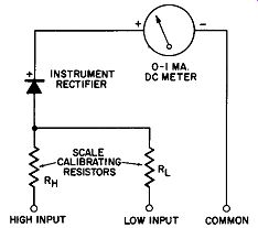
Fig. 12-5. Multi-Range Rectifier Type AC Voltmeter.
Another way of saying the same thing is to say that the DC voltmeter just described has a sensitivity of 1000 ohms per volt.
When we apply the half-wave rectifier to the voltmeter circuit to permit measurements in AC circuits, this value of 5000 ohms for the 5 volt range is too much. One reason for this is that in the half-wave rectifier circuit, current flows during every other half cycle of the input in the manner previously explained; the other reason is that we have neglected to take into account the waveform of the alternating input.
If our AC input were rectangular as shown in Fig. 12-6, the half-cycle flow of current would necessitate the reduction of the 5000 ohms resistance by one half to secure full scale indication on a half-wave circuit. This multiplier resistance of 2500 ohms assumes that the input is alternating but of a rectangular waveform, for we have assumed that the 5 volts full scale input was applied during the whole half-cycle period.
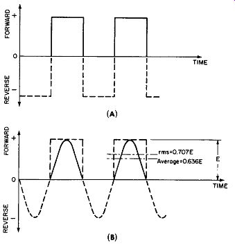
Fig. 12-6. Rectangular and Sine Waveforms.
We know that when 5 volts AC is applied to our meter (for which we desire a full scale indication), we mean 5 volts root-mean-square. We also know from previous explanations of alternating current circuits that the peak value of a sine wave is 1.414 time the rms value or if the peak value is E then the rms value is 0. 707E, that is, E divided by 1.414. Furthermore, we know that the average value of a sine wave is 0.636E. Thus, when we apply 5volts rms to our rectifier type voltmeter, the peak value of the voltage applied is 5 times 1.414 or 7.070 volts; and the average value of this voltage is 7.070 times 0.636 or approximately 4.5 volts. We are interested in this average voltage for this is the value of the potential which causes the average current to flow--the value of current which is indicated by our moving coil meter. The average value of voltage, 4.5, divided by the average full scale current, namely 0.001 ampere, would indicate a multiplier resistance of 4500 ohms, and since this average voltage is present but half of the time (due to the half-wave rectification of the AC input), we must halve the series multiplier resistance if we desire the full scale current to be 0.001 ampere; hence, it appears that the value of this multiplier resistance is 2250 ohms.
One additional factor must be included in our computations to approach the ultimate value of this multiplier resistance; the forward resistance of the half-wave rectifier must be considered. Correcting for the voltage drop across the forward resistance a value of about 2000 ohms for the multiplier resistance for the 5 volt range is just about right; and for the 100 volt range one would say that 20 times 2000 ohms or 40,000 ohms was correct. These computations have neglected the resistance of the moving coil of the meter which is in series with the multipliers. For a typical 0 to 1 milliampere DC meter this resistance may range from 50 to 200 ohms and must be considered as part of the multiplier.
This factor and the lengthy discussion as to why the multiplier resistance amounts to about 400 ohms per volt instead of the familiar 1000 ohms per volt are given so that the reader will better understand some of the problems in the commercial application of the instrument rectifier. Here however, we want to see chiefly why the rectifier's reverse current gets us into difficulty when we attempt to construct a multi-range AC voltmeter such as that shown in Fig. 12-5.
We have tried to design a two range, half-wave rectifier type AC voltmeter having the ranges of 5 and 100 volts AC rms. We have computed the values of the multiplier resistances in the foregoing and found them to be 2000 ohms and 40,000 ohms respectively. Upon testing the newly de signed circuit we find that when we apply 5 volts we obtain a full scale pointer deflection when using the 5 volt range of the instrument. However, when we use the 100 volt range and apply 100 volts AC rms to the input, we find that the pointer deflects only about 50 percent of full scale. The reason for this discrepancy is that our computations for the multiplier resistance have been based upon forward current alone-assuming that the reverse resistance of the rectifier was infinite. Actually this reverse resistance of the half-wave rectifier may be for example, 50,000 ohms resulting in a reverse or leakage current of 0.1 milliampere on the 5 volt range and 2 milliamperes on the 100 volt range; these results are obtained by using Ohm's law to determine the full scale reverse current. The full scale forward current is fixed for the two ranges and is 5 volts divided by our multiplier resistance of 2000 ohms or 2. 5 milliamperes for the low range and 100 volts divided by 40,000 ohms or again 2.5 milliamperes for the high range. The forward to reverse current ratio on the low range of our simple voltmeter is 2.5/0.1 or 25, whereas for the high range it is 2. 5/2 or 1. 25. This decrease of current ratio as a result of an increase of reverse direction voltage de creases the rectification efficiency causing a reduced pointer deflection for the 100 volt range. This experience clearly shows that for more uniform full scale pointer deflection in multi-range, rectifier-type AC voltmeters someway must be devised to reduce the reverse voltage across the half-wave rectifier.
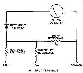
Fig. 12-7. Rectifier-Type AC Voltmeter Using Resistive Shunt.
The Half-Wave Instrument Rectifier Circuit With Resistance Shunt
An arrangement which will hold the reverse voltage to a low value is obtained by shunting the series combination of the meter and the half-wave rectifier with a resistance. A circuit using this idea in a two-range AC voltmeter is given in Fig.12-7. The reader will note that it is similar to the previously discussed circuit of Fig. 12-5 but with the addition of Rs the shunting resistor. This shunting resistor, in conjunction with the active multiplier resistance, provides a voltage divider arrangement so that the voltage drop across the rectifier-meter combination is held to the same low voltage on all ranges of the voltmeter when the input potential has reversed its polarity (as during the non-conducting half cycle on an AC source). By this circuitry, the value of the reverse or leakage current through the rectifier and meter has the same value for both ranges of the voltmeter.
With the forward to reverse direction current ratio fixed by this shunt resistance scheme, the rectifier efficiency and the meter scale curvature are alike on both ranges.
The value of the shunt resistance has two limits: infinity, as in the example of Fig. 12-5 wherein we ran into the scale trouble on the two desired ranges; and short-circuit, in which case no useful meter indication can be obtained. Between these two limits we can experimentally find a value of shunt resistance which will make the scale of the two ranges of our voltmeter about uniform. Say that a typical value for this shunt is about 1000 ohms. Having applied this value of shunt resistance we find that for our gain in uniformity of scale between the two ranges, we must pay by a reduction of meter sensitivity in the form of decreased values for the multiplier resistors--or in a lower "ohms per volt". Moreover, the scheme of holding the reverse direction voltage to low values by this shunt circuit also works in a like manner for the forward direction voltage; that is, the shunt circuit maintains the forward voltage to a low value at full scale regardless of which range is used. At half scale the voltage developed across the shunt (which is part of the voltage divider circuit when considered in conjunction with the active multiplier) is one half that required for full scale indication and the same proportion holds for any partial scale voltage. Operated under these conditions the current density property of the rectifier causes the AC meter scale to depart from linearity resulting in bad crowding towards the zero end of the scale. This current density property is the familiar characteristic of the rectifier in which the forward resistance is not fixed but decreases as the current through the rectifier increases. This forward resistance has a maximum value for small magnitudes of forward current and reduced values for larger forward current flow. When the rectifier input voltage is maintained fixed by a resistive shunt as in Fig. 12-7 to a value proportional to the voltage impressed across the instrument terminals, the resistance increase in the rectifier causes less current to flow in the rectifier meter circuit which further increases the rectifier resistance because of its current density property, until an equilibrium is reached at a point on the meter dial substantially below the point on the linear scale corresponding to the voltage being measured.
We can see that the shunting resistor idea of Fig. 12-7 has made possible uniform AC scales for the two (or more, if desired) ranges of our voltmeter but the price we have to pay for this advantage is reduced sensitivity and a crowded graduation for the lower portion of the meter scale.
The Half-Wave Instrument Rectifier Circuit With Rectifier Shunt
If we could devise a shunt which would be active during the nonconductive cycle of the input potential to the meter, and inactive during the conducting cycle of the input potential to the meter, we might approach our ideal of uniform scales between ranges, a linear scale, and suitable sensitivity. This thought suggests using a half-wave rectifier similar to the meter rectifier as the shunting element of the voltage divider of the circuit shown in Fig. 12-7. This new arrangement is given in Fig. 12-8.
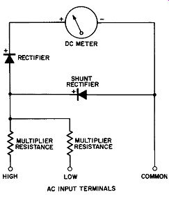
Fig. 12-8. Half-Wave Rectifier-Type AC Voltmeter with Rectifier Shunt.
We are now in the fortunate position of having a shunt which is active during the reverse polarity half-cycle of the input and this reverse direction voltage is held to a lower value than can be realized by any practical resistive shunt scheme. Other advantages of the method of Fig. 12-8 are: the shunt rectifier is not active during the forward half cycle with the result that the input voltage to the rectifier meter combination approaches the linear DC scale, and the higher sensitivity of the circuit of Fig. 12-5 is recovered.
The Full-Wave Instrument Rectifier Circuit
The three instrument rectifier circuits discussed thus far are half-wave operated and are suitable at input frequencies higher than say 50 or 60 cycles per second. As the frequency of the input is reduced or where the input is of a lower frequency, say 25 cycles per second, the above circuits are no longer satisfactory. Their failing is that at lower frequencies the inertia of the meter movement is not sufficient to reduce or "snub" the pointer vibration caused by the half cycle flow of current. That is, the period of no-current conduction is long enough at low frequencies to cause the hair springs of the meter moving system to partly restore the meter pointer towards zero. During the next conductive half-cycle, a pulse of forward current pushes the pointer up again.
At 50 to 60 cycles per second these periods of activity and inactivity occur so fast that the inertia of the coil and pointer system average out the vibration. Another reason that the half-wave circuits described may not be satisfactory even at medium frequencies is that more instrument sensitivity may be required. We can approximately double the sensitivity and at the same time reduce the pointer quiver by eliminating the non-conducting half-cycle if we can devise a full-wave instrument rectifier circuit to overcome these limitations.
A full-wave circuit is shown in Fig. 12-9.
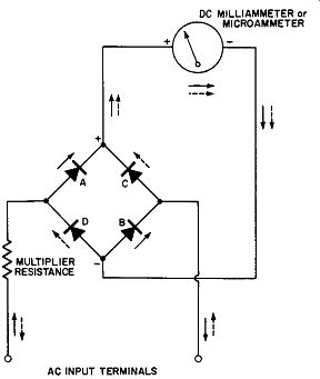
Fig. 12-9. A Full-Wave Rectifier-Type AC Voltmeter.
The DC output terminals of the full wave instrument rectifier are applied directly to the corresponding polarity terminals of the DC meter whereas the AC input is applied to the AC terminals of the bridge rectifier with one branch of the input having a suitable multiplier resistance in series. By this method not only is the instrument sensitivity on AC input doubled over the half-wave circuits and pointer quiver minimized at low frequency inputs, but in addition there is no requirement for resistive or rectifier shunt circuits to permit uniformity of meter scales on multi-range meters be cause both halves of the input cycle are utilized for the operation of the meter. On one half of the input cycle the two rectifiers A and B pass the current through the meter, and during the next half cycle the two rectifiers C and D pass current through the meter. During the inactive half cycle some reverse current does flow through the "non-conducting" rectifiers. Upon comparison with the diagram of Fig. 12-8 it will be noted that this scheme of Fig. 12-9 is the full wave version of the half-wave circuit shown in Fig. 12-8. The full wave version is superior over the half-wave circuit because of improved sensitivity and minimized pointer quiver at frequencies below 50 cycles per second.
The Full-Wave Instrument Rectifier Circuit Using Two Rectifiers
H economy in the full-wave operation of the instrument circuit is necessary, this can be obtained at some loss of linearity and sensitivity by replacing two of the half-wave rectifiers in the full ·wave bridge by resistors. There are two such arrangements, the first of which is given in Fig. 12-10.
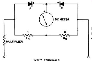
Fig. 12-10. A Full-Wave Rectifier-Type AC Voltmeter Using Two Rectifiers.
Upon comparison with the circuit of Fig. 12-9 it can be observed that half-wave rectifiers B and D have been replaced with two identical resistors. The arms of the full-wave bridge containing the identical rectifiers and the resistors are labeled after the same pattern as established for Fig. 12-9. The reader can trace the circuit mentally to verify that during one half cycle the forward current flows from the source through the multiplier resistance, through rectifier A, the meter coil, and thence through resistor B back to the AC source. During the succeeding and reverse half cycle the forward current from the AC source flows through rectifier C, the meter coil, and thence through resistor D, the multiplier resistance, and back to the source. During the conducting cycle each rectifier and its corresponding resistor behave in the manner described for the half-wave rectifier circuit with resistive shunt of Fig. 12-7; this circuit in Fig. 12-10 is essentially a full-wave version of Fig. 12-7. The full-wave version of Fig. 12-10 has the advantage over the half-wave version of Fig. 12-7 of almost twice the sensitivity and minimized pointer quiver for moderately low frequencies. Like the half-wave version, however, the full-wave circuit of this metering circuit has an AC scale which is crowded near zero and uniformity of scales for multi-range instrumentation is retained.
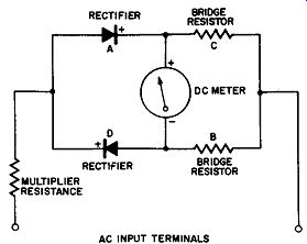
Fig. 12-11. Another Method of Connecting a Full-Wave Rectifier-Type AC Voltmeter
Using Two Rectifiers.
The other full-wave meter circuit which reduces the pointer quiver at low frequency inputs but which has poorer sensitivity is drawn in Fig. 12-11. The chief advantage of this arrangement of rectifiers and their associated resistors in the full-wave bridge is that by proper experimental choice of these associated resistors the AC scale of the voltmeter can be made nearly linear.
Errors in Instrument Rectifiers
In our introductory material on instrument rectifiers we discussed avoidable causes which may result in errors in rectifier type AC meters; these, you may recall, were mechanical damage due to careless handling, chemical action due to improper processing or exposure to contaminating atmosphere, or overheating the active areas of the rectifier when soldering the rectifier assembly into the application circuit.
There are four properties of instrument rectifiers which can cause undesirable errors which cannot be avoided by processing or handling but most of which can be compensated for by suitable circuit design. These error properties may be listed as:
a. Waveform of input signal.
b. Frequency.
c. Ambient temperature.
d. Current density.
Waveform Error
We have described rectifier type instruments as indicating the average value of the alternating current. Usually this alternating current is of the sine-wave form and the meter scale is calibrated to read rms values of the sine wave although its indication is proportional to the average value of the wave form, namely 0.636 times the peak value of the applied sine wave. For this reason when distorted sine waves, for example, alternating voltages of essentially sine characteristics but rich in harmonics, or alternating current waveform other than sine such as triangular or square wave are applied to the input terminals of the rectifier-type meter, the indications are no longer correct--the meter pointer deflection is proportional to the average value of the applied waveform but the rms reading is no longer correct. That is, the rms value of the unknown waveform which is not a true sine wave is not related to its average value by the same ratio as that of the sine-wave form. In the sine wave, the rms value is related to the average value by the ratio 0.707 to 0.636 or 1.11, which is called the form factor of the sine wave.
There is no means for compensating for this type of waveform error but fortunately, if the problem is recognized the operator need not be led astray. In most cases where rectifier type AC instruments are applied the waveform is sinusoidal and the meter readings are accurate.
Frequency Error
We have already discussed the difficulties encountered when measuring alternating potentials having frequencies below 30 cycles per second when using rectifier-type AC measuring instruments. If the rectifier circuit involved is half wave, a serious pointer quiver precludes accurate measurement below 20 to 30 cycles per second. This condition is minimized or practically overcome for this frequency range by the application of full-wave rectification. When the input potential is of a still lower frequency, say 5 to 10 cycles per second, even the full-wave circuit will not eliminate an objectionable and cyclic pointer oscillation. Ji the rectifier type AC instrument is to be used only for low frequency, and a small delay in pointer indication after the voltage is applied or changes its level is not objectionable there are two easy ways to overcome this low frequency pointer oscillation.
In the first method the meter moving system (coil and pointer assembly) is specifically designed to have considerable mechanical inertia so that its period of oscillation will be low and the pointer system will give the desired average indication rather than an oscillation about the mean indication.
A way to accomplish this is to add an aluminum vane to the pointer system and enclose this vane in a chamber with a predetermined vent; this scheme is equivalent to the pneumatic dash-pot idea of snubbing mechanical oscillations.
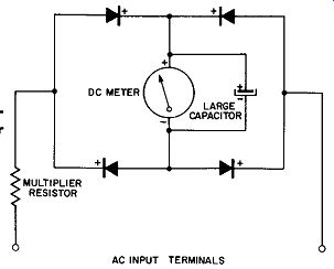
Fig. 12-12. A Rectifier Type AC Meter Circuit for Low Frequency Work.
The second method of damping pointer oscillation of a rectifier type AC meter at the lower input frequencies is illustrated by the diagram of Fig. 12-12. Here the familiar full-wave, rectifier type AC meter circuit has a large capacitor shunted across the DC meter. This capacitor acts as a large reservoir or tank for the rapidly varying DC potentials impressed across its terminals and across the shunted DC meter. It functions to average out the oscillation potential and present to the meter terminals an averaged potential. This is desired to cause an average current indication and the addition of this capacitor smoothens out the pointer response at low frequencies. The value of this capacitor depends upon the meter and the circuit constants and may have a capacitance of from several hundred to several thousand microfarads; especially processed electrolytic capacitors have been used.
As the frequency of the applied potential of constant amplitude to a conventional rectifier type AC meter is increased the pointer deflection, which should remain constant, begins to decrease and at some high value of applied frequency the indication may be zero.
(B) Rectifier-Type Meter Reading Versus Applied Frequency.
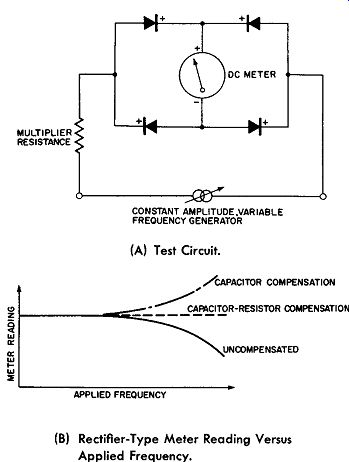
Fig. 12-13. Frequency Response of Rectifier-Type AC Meters.
Fig. 12-13A shows a test circuit which may be used to obtain the frequency response of the rectifier type AC meter.
A variable frequency generator, having its output voltage set at a constant-level of say 10 volts, is varied over the frequency range of particular interest, say, 20 to 50,000 cycles per second. A typical frequency response is shown by the solid curve of Fig. 12-13B. It can be seen that as the applied frequency increases, the meter reading decreases at the higher frequencies even though the input is maintained constant.
This loss of meter reading at the higher frequencies is the result of the following factors:
a. Capacitance effect of the rectifier assembly.
b. Impedance of meter coil and multiplier.
The capacitance property of the rectifier is equivalent to the effect obtained when the ideal rectifier is shunted by a small capacitance. See Fig. 12-14. With this picture of the equivalent circuit it is easy to see that at high frequencies the rectifier becomes less efficient, for the reverse resistance is reduced by the decreasing reactance of the shunting capacitor across it. It is true that the smaller disc area of the instrument type rectifiers is conductive to less shunting capacitance and therefore, this type rectifier is more efficient at the higher frequencies.
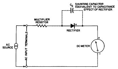
Fig. 12-14, Equivalent Circuit illustrating Capacitance of Rectifier at
Higher Frequencies.
Another factor which causes reduced meter readings at the higher frequencies is the meter coil impedance. The reader will remember that the moving coil of the meter is essentially equivalent to a small inductance in series with the coil resistance through which the rectified current pulses must pass. This equivalent circuit is shown in Fig. 12-15.
There are small stray capacitance effects due to the moving coil structure also; as these are effective at frequencies much higher than that in which we are interested, they are neglected here.
Naturally, as the input frequency increases the impedance of the moving coil increases because of the inductive component of the moving coil--again causing a reduction in the current through the meter. The simplified equivalent circuit of the meter moving coil resistive and inductive components is given in Fig. 12-15. If the multiplier resistance is wire wound, this element of the rectifier type AC meter will also have an increasing impedance tending to further decrease the meter current at input frequencies of higher order.
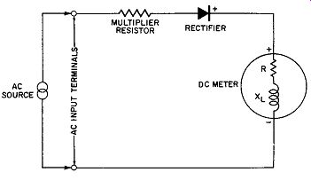
Fig. 12-15. Simplified Equivalent of DC Meter Coil at High Frequencies.
Fig. 12-16 shows circuit compensation means to overcome this type of decrease in meter reading. In Fig. 12-16A the multiplier is shunted by a small capacitor which decreases in reactance as the input frequency increases. This idea makes it possible to reduce the impedance of the shunt circuit, consisting of the multiplier resistance and the capacitor, which is in series with the rectifier and the DC meter. Over a range of frequencies this reduction of circuit impedance can compensate for the increasing meter coil impedance and that of the multiplier, and for the decreasing rectifier efficiency because of its capacitance effect.
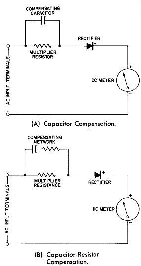
Fig. 12-16. Compensation for High-Frequency Errors In Rectifier Type AC
Meters. (A) Capacitor Compensation. (B) Capacitor-Resistor Compensation.
A rise in the frequency response curve may take place by this compensation scheme because the multiplier shunting capacitor is over-compensating the other errors. See the dot-dashed curve of Fig. 12-13B. This over-compensation may be minimized by adding a suitable value of resistance in series with the shunting capacitor as in Fig. 12-16B. This resistor limits the amount of compensation possible with any given shunting capacitor, and by the proper selection of capacitance and resistance, a flatter response at higher frequencies may be obtained as represented by the dashed curve of Fig. 12-16B. The problem is not easily represented by simple equivalent circuits, so that values for the capacitance and the resistance will have to be determined by trial; more over, the response curve at best may not be flat over the entire high-frequency range, but may have dips and humps which are caused by the stray capacitances combining with the circuit inductances to cause series or parallel resonance conditions at certain frequencies.
Ambient Temperature Error
Ambient temperature errors are caused by changes in the forward and reverse direction resistance in the rectifiers used in rectifier-type AC meters when the temperature changes. In the copper-oxide type of rectifier both the for ward and reverse direction resistance decrease with in creasing temperature. This represents a negative coefficient of resistance. This resistance change causes errors in the meter circuit which are dependent upon the circuit type used and upon the operating conditions selected for the rectifier.
In instrument circuits similar to that of Fig. 12-8 or Fig. 12-9 the temperature error is directly proportional to the rectifier resistance change. This error will be most noticeable on the low voltage range where the series multiplier will not have a large enough ohmic value to swamp out resistance changes of the series rectifier. The temperature error will be quite small on the high voltage ranges, where the series multiplier resistance is so large that moderate ohmic changes of the rectifier, because of temperature changes, will be negligible.
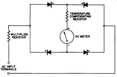
Fig. 12-17. Compensating Resistor In Series With Meter for Temperature Effects.
One way to compensate for temperature errors is to include an additional resistance in series with the meter as shown in Fig. 12-17 for the full-wave circuit. This circuit trick increases the reverse direction voltage drop across the rectifier so that enough reverse current flows at the higher temperatures to compensate for the increased forward current. This scheme also improves the AC scale linearity but the limit to the ohmic value of this series resistance is approached when the maximum reverse direction voltage reaches the safe operating limits of the rectifiers used.
Another scheme to compensate for temperature effects in rectifier-type AC meters is to use positive temperature coefficient multipliers in conjunction with the positive co efficient of the moving coil to compensate or minimize the negative coefficient of the rectifiers. This only gives partial correction at low voltage ranges of the meter because the negative coefficient of the rectifier is greater than that obtained for commercially available positive temperature co-efficient multiplier resistors.
Current Density Error
We have learned that the forward resistance of rectifiers is not constant but is dependent upon the value of the forward current; for large values of forward current this forward resistance is low; for small values of forward current this for ward resistance is large. The reverse direction resistance remains constant at any given temperature. This dependency of the ohmic value of the forward resistance upon current flow causes multi-range instruments to track poorly on a common scale because this rectifier resistance change is a substantial percentage of the multiplier resistance value on low voltage ranges and almost negligible on higher voltage ranges. Conant Laboratories have devised a shunt circuit using rectifiers for the shunting elements. This type of circuit provides almost exact compensation for errors due to current density variation. It also corrects errors due to temperature changes and partially corrects frequency errors.
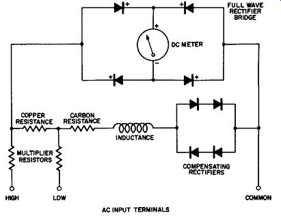
Fig. 12-18. Compensated Rectifier-Type AC Volt meter.
The completely compensated circuit after this pattern is drawn in Fig. 12-18. For further information, the reader can refer to "Instrument Rectifiers" by H. B. Conant, Conant Laboratories, Lincoln, Nebraska.