AMAZON multi-meters discounts AMAZON oscilloscope discounts
Introduction
There are a number of interesting and important applications for an electrical device which permits current flow in one direction but obstructs the current flow in the reverse direction when the polarity of the applied potential is reversed.
This can be accomplished electromechanically by means of a polarized relay but the more elegant solution is the application of the property of unilateral conduction of a metallic rectifier.
When used for this kind of application, metallic rectifiers are called electric valves.
Selenium and copper-oxide types of metallic rectifiers have both been successfully used as electric valves; each new application requires specific consideration to determine which set of rectifier properties can be used to best advantage. For example, in an arrangement wherein the current flows through a selenium type electric valve in the forward direction most of the time and rarely is the polarity of the applied voltage re versed, then, at these rare intervals when the applied potential is reversed the reader will recall that there will be a high reverse leakage current until the rectification junction has had an opportunity to reform. This high reverse leakage current is of very short time duration and it may or may not be objectionable in the problem considered. If the electric valve actuated device has a reasonable mechanical or thermal inertia then this surge of reverse current is of little harm. If the actuated device is a fast acting electro-mechanical relay, this leakage current may cause a false actuation of this relay resulting in improper operation of subsequent controlled circuits.
This momentary reverse current may have a magnitude of 10 to 20 percent of the normal forward current when the rated DC voltage is applied per rectifier junction. If this value of reverse current causes improper actuation of the circuit, the reverse direction voltage per rectifier junction may be reduced by adding more plates to the selenium type electric valve, until satisfactory performance is attained. Or it may be that a copper-oxide type rectifier is better for the job considered because of its better electrical stability and no need for electro forming.
In circuit applications of metallic rectifiers as electric valves in which there is a cyclic change of the applied potential, there is no difficulty from the electroforming current effect, and selenium type rectifiers may be used.
Where the manufacturer's tables, or specifications, give the DC ratings of the rectifier plates (these ratings are the most useful for electric valve problems), the reader will find that these DC ratings are somewhat higher than the ratings of the same plates when used as conventional rectifiers; the reason for this is that the absence of alternating current in these valve applications precludes heating due to leakage currents on a continuous basis.
A few examples of the application of metallic rectifiers as electric valves will be given in this Section to illustrate these possibilities.
Metallic Rectifiers as Voltage Surge and Arc Suppressors
Metallic rectifiers can be used as electric arc suppressors to preserve contact life of switches and relays used in circuits having inductive loads. This application is shown in Fig. 13-1.
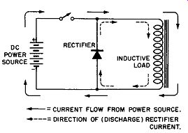
Fig. 13-1. Metallic Rectifier as an Arc Suppressor.
Here, the use of the metallic rectifier as a device for absorbing inductive energy so as to prolong switch contact life is dependent upon the unidirectional property of the half-wave rectifier used as an electric valve.
As shown in this figure the rectifier is connected in parallel with the inductive load which may be a motor, solenoid, a relay, or an electromagnet. When the switch contacts are closed (these contacts may be that of a manually operated switch or the control contacts of a sensitive relay), the current flow from the power source is through the inductive load with little or practically no current flow through the rectifier be cause the applied polarity is in the high resistance or reverse direction.
When the switch is opened, the load current still tries to flow in the same direction as before and now it is possible for it to do this because of the shunting rectifier which pro vides, by its low forward resistance, a suitable discharge path as represented by the dotted arrows. Because the rectifier presents a low resistance circuit, a discharge path is provided for the stored inductive energy and the inductive voltage rise across the load is suppressed. This helps preserve the switch contacts from the destructive arcing normally present and the stressing and ultimate breakdown of the coil insulation by the induced surge voltages.
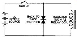
Fig. 13-2. An Improved Arc Suppressor Circuit Using Two Rectifiers.
An additional improvement on this voltage surge or arc suppression circuit using metallic rectifiers as electric valves has been developed by Federal Telephone and Radio Corporation and its affiliates. This development uses selenium type rectifiers and may also be applied to relays, contactors, magnets, solenoids, or any inductive device powered by a DC source. The principle of this development is also to limit the self-induced voltage in these inductive devices, and thereby increase contact and wire insulation life. Fig.13-2 shows the improved version of the application of the electric valve action of metallic rectifiers.
In the original surge suppression circuit, see Fig. 13-1, a half-wave selenium rectifier is used to provide contact protection in DC circuits by shunting the inductive device. The valve action of the metallic rectifier blocks the flow of current from the DC source when the coil is energized, but offers little resistance to the reverse or induced current when the circuit is opened by the relay or actuator contacts.
The new type voltage surge suppressor, Fig.13-2, uses two or more selenium rectifier cells connected "back-to-back".
The basic idea here is to employ the rapidly decreasing resistance of the selenium rectifier cell with the increasing reverse voltage as shown in Fig. 13-3.
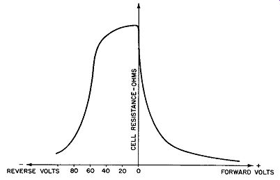
Fig. 13-3. Reverse Voltage Versus Rectifier Cell Resistance for Selenium
Type Cell.
The reader can verify from the voltage-resistance curve that the reverse resistance at minus 10 volts is many times greater than that at minus 80 volts. When an electric valve fashioned of selenium rectifier cells mounted back-to-back is connected across an inductive load, one of the rectifier cells blocks the current from the battery or DC source, while the other rectifier cell effectively limits the self-induced voltage rise across the coil when the work current is interrupted as by opening the relay or actuator contacts. In this way the magnetic energy stored in the inductance is dissipated in the resistance of the selenium rectifier and the coil. An advantage obtained by this circuit is that radio frequency interference is reduced because oscillatory discharge is suppressed.
Another advantage of this circuit is that because of the back-to-back construction the reverse resistance to the supply voltage is greater and the normal leakage current from the DC source is low resulting in economy of operation where the suppressor is used across the power source on a continuous duty basis.
One other advantage of this circuit is that it reduces the release time of the system when the inductive device is a relay.
When the original circuit involving the half-wave selenium rectifier is used the self-induced voltage surge is minimized but the release time is excessive. The new circuit arrangement for reducing voltage surge may improve the release time by a factor of 5 to 1.
For voltage surge applications involving telephone re lays, magnetic clutches, or like devices, protectors of the type shown in Fig. 13-2 are available in a packaged unit 5/8 inch long by 3/8 inch in diameter. When the work circuit involves 120 volts DC and the inductance device uses 1/2 ampere, the surge suppressor is about 1 inch long and 1/2 inch in diameter.
In external appearance these voltage surge suppressors look like paper capacitors.
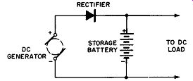
Fig. 13-4. Reverse Current Relay Circuit.
Metallic Rectifiers as Relay Devices
A common application of the metallic rectifier as an electric valve is as a cut-out or reverse current relay in battery charging circuits. See Fig. 13-4. While the generator is operating, it is able to supply current to charge the storage battery and help carry the DC load, whenever its output voltage is great enough. When its output voltage drops or the generator stops, the battery cannot discharge through the generator windings because of the valve characteristics of the metallic rectifier cell. The rectifier behaves as a reverse current cut-out relay without physical contacts which are subject to vibration, pitting, or burning.
Duplex Operation of Controls
It is often desirable to actuate two independent controls at the end of a single, two wire control line, where ordinarily a three or four wire line would be necessary. A solution to this problem has been offered by the skillful application of the unilateral conduction or valve action of two half-wave rectifiers and two relays, as shown in Fig. 13-5. In this circuit relay REl can be closed when the double-pole, double-throw switch engages the set of contacts "B". In this position the lead common to the rectifiers is positive and the current passes from the source through rectifier D1, thence through relay coil REl, through the lead common to the relays, and back to the negative terminal of the DC power source. With the double pole, double-throw switch in position "B", current can not flow through rectifier D2, therefore, relay No. 2 remains open.
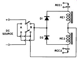
Fig. 13-5. Duplex Operation from a DC Source.
When the double-pole, double-throw switch is positioned to engage the set of contacts labeled "A", the lead common to the rectifiers is connected to the negative terminal of the DC power source; now the current flows through rectifier D2, through relay coil RE2, thence through the lead common to the relays and back to the positive terminal of the DC power source.
It is to be noted that now the current cannot flow through rectifier D1; therefore, relay REl remains open. Hence, with the duplex circuit of Fig. 13-5 either relay control circuit RCC1 or RCC2 may be closed when desired by properly positioning the double-pole, double-throw switch.
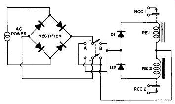
Fig. 13-6. Duplex Operation from an AC Source.
When the power source is alternating, another metallic rectifier assembly may be used to convert the alternating current into direct current to make possible the operation of the above scheme from the ordinary commercial AC power lines. This "all AC" arrangement is pictured in Fig. 13-6.
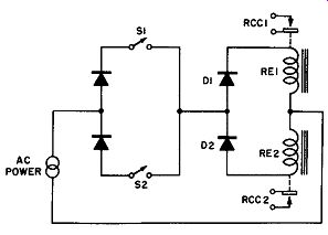
Fig. 13-7. Simplified Method of Obtaining Duplex
Operation from an AC Source.
The AC duplex operation of the control relays may be further simplified by the elimination of two of the half-wave rectifiers at the sending or control end of the line. See Fig. 13-7. The principle of the operation is the same as before with individual control over relays RE 1 and RE2 being obtained at the sending end of the two lines by closing either switch S1 or switch S2. A further advantage secured by this simplification is that, when switches S1 and S2 both are closed, both control relays may be actuated simultaneously from the sending end of the two lines.
Square Wave Operation by Metallic Rectifiers
For circuit testing purposes it is necessary to have available a "square" waveform of potential. For example, a cathode-ray oscilloscope voltage calibrator uses a square wave source as a means of calibrating the amplitude of the unknown waveforms seen on the oscilloscope screen.
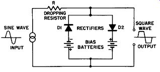
Fig. 13-8. Square Wave or Clipping Circuit Using Metallic Rectifiers.
By utilizing the electric valve property of the metallic rectifier, but delaying its action by means of bias potentials, it is possible to obtain "square-wave" voltages from sine wave sources. See Fig. 13-8.
On either sine wave alternation, rectifier elements D1 and D2 do not conduct until the sine wave voltage exceeds the biasing potential shown; after this point in the voltage rise the rectifiers condt1ct causing a heavy voltage drop in the common dropping resistor R. This results in an effective "chopping" off of the tops of the sine wave alternations giving an output appearing similar to a "square wave".
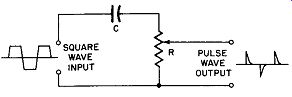
Fig. 13-9. Circuit for Obtaining a Pulse Waveform from a Square Wave Input.
By passing this square wave through a differentiating circuit (see Fig.13-9) comprising a small capacitor in series with a large resistor, the voltage waveform obtained across the resistor consists of pulses which are useful in the laboratory for tripping thyratron circuits or for control purposes in electronic circuits.