AMAZON multi-meters discounts AMAZON oscilloscope discounts
Introduction
There are a number of applications of metallic rectifiers which do not fall under the previous classifications. These miscellaneous, but important, jobs for metallic rectifiers will be described in this section.
Metallic Rectifiers for Magnetic Amplifiers
Since World War II magnetic amplifiers have become exceedingly popular for many control problems. This type of amplifier, which is extremely reliable and permits substantial power amplification, does not use electronic tubes, but a combination of saturable core reactors and metallic rectifiers.
Because of this combination, this type of amplifier is ready to operate as soon as power is applied--there is no warm-up time. It is so rugged that it can be applied to fire control problems and it will easily withstand the shock. Moreover, when using this type of amplifier, the replacement and maintenance problems are greatly minimized.
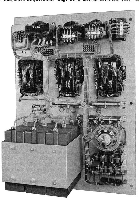
Fig. 14-1. Magnetic Amplifier Type Voltage Regulator for 200 KVA Generator
Using Three-Phase Metallic Rectifiers. (Courtesy of Vickers, Inc.)
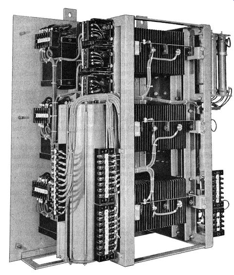
Fig. 14-2. Magnetic Amplifier Type Voltage-Regulator for 1 00 KVA Generator.
(Courtesy of Vickers, Inc.)
The chief disadvantage of the present magnetic amplifiers is that the frequency range is usually limited to a few hundred cycles per second, or at best through the audio frequency range with special circuit arrangements. Ultimately, with better saturable core materials and metallic rectifiers, the frequency range may be extended into the radio frequency range. A further disadvantage of present magnetic amplifiers is that they consume some power from the signal source.
Within the limitations of frequency range and power consumption from the signal source, the magnetic amplifier provides stable and ample power amplification for AC and DC usage. It is particularly useful for motor controls, regulated power supplies, non-mechanical power relays, and the like.
Figs. 14-1 and 14-2 illustrate two practical applications of magnetic amplifiers. Fig. 14-1 shows the rear view of a magnetic amplifier type generator voltage regulator for a 200 kva generator. This magnetic amplifier uses three-phase, full-wave rectifiers. The rectifiers are of the selenium type, convection cooled, and deliver 3.2 to 4.8 kw DC.
The power rectifiers of the magnetic amplifier can be seen in the bracket mounting in the lower left-hand corner of the control panel. Other and smaller selenium rectifier stacks are also used as components for the preamplifier stages of this magnetic amplifier.
Fig. 14-2 is a view of a generator voltage regulator for a 100 kva generator. It also uses three-phase, full-wave selenium rectifiers. These are convection cooled and deliver 2.1 to 4 kw DC, and are located in the right-hand portion of the control panel, mounted one above the other.
In this guide we are not going to deal with the circuitry of magnetic amplifiers because this subject is a big field all its own. In an elementary manner this subject is discussed in the writer's book entitled "Saturable Core Devices" to which the interested reader is referred. Our concern in this guide is with metallic rectifiers and in particular with metallic rectifiers suitable for magnetic amplifiers. The chief requirement for this type of application is a high forward to reverse current ratio so as to make best use of the properties of the magnetic core of the saturable core device. Currently, the selenium type rectifiers are most commonly used in this application and even these must be especially processed and selected. One means to secure the better current ratio needed is to derate the conventional 26-volt rectifier plates to 16 or 20 volts. By this scheme a current ratio of 500 to 1 can be attained and by careful selection of the rectifier plates an additional 2 to 1 increase in forward to reverse current ratio is achieved or all together a current ratio of 1000 to 1.
This ratio of forward current to reverse current of 1000 to 1 is still short of the ideal ratio required by presently available magnetic cores; however, one manufacturer has announced selenium rectifiers stacks consisting of 5 by 6 inch plates, connected as a single-phase, full-wave bridge that have forward to reverse current ratios as high as 4000 to 1 when the stack is derated to 16 volts.
Power Frequency Multipliers
For experimental test and measurement purposes it is often desirable to have an alternating power source with a higher frequency of alternation than that obtained from the power line. By using the valve action of the metallic rectifier it is possible to double and quadruple the fundamental power frequency by simple circuits.
Fig. 14-3 shows a frequency doubler circuit. Fig. 14-4 indicates the magnetizing current, flux set-up, and the voltage output. The solid arrows in Fig. 14-3 shows the flux setup by coil No. 1 when terminal M of the power supply voltage is positive. For this polarity of applied voltage, primary No. 2 is carrying a negligible current because of the oppositely connected rectifier D2, hence negligible magnetizing force. In the next half cycle, indicated by the dashed line portion of the applied voltage curve, primary No. 2 magnetizes the core in the direction shown by the dashed-line arrow.
*Published by the Scientific Book Publishing Co. Vincennes, Indiana.
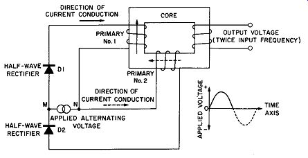
Fig. 14-3. A Frequency Doubler Circuit Using Two Primaries and Two Rectifiers.
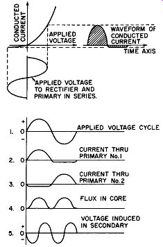
Fig. 14-4. Analysis of Frequency Doubler Circuit. (A) Graphical Analysis of
Conducted Current Waveform. (B) Waveform Analysis of Frequency Doubling.
Despite the reversal of the applied voltage the rectifiers behave as commutating devices to cause the current to flow in such a direction as to setup flux in the same direction. This is clearly shown in Fig. 14-4B where in waveform No. 1 is the applied voltage; waveform No. 2 shows that during the positive half cycle only coil No. 1 is energized; waveform No. 3 shows that only coil No. 2 is energized during the negative half cycle of the applied voltage. Coils No. 1 and No. 2 are so poled on the core that the flux is set up in the same direction as shown in waveform No. 4. The rate of change of this flux curve will produce the voltage generated according to Lenz' s law. This voltage curve is shown in waveform No. 5 in Fig. 14-4B.
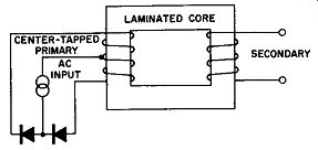
Fig. 14-5. Frequency Doubler Circuit Using Two Rectifiers and a Center-Tapped
Primary.
The arrangement may be simplified, for example, it is seen that coils No. 1 and No. 2 of Fig. 14-3 have a common connection. Hence, if but a single coil provided with a center tap were mounted on the core, in place of the two coils shown, the results would be equivalent to that described but the apparatus would be simplified. This form of the doubler is shown in Fig. 14-5.
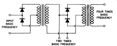
Fig. 14-6. A Frequency Quadrupler Circuit.
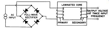
Fig. 14-7. A Frequency Doubler Circuit Using Full Wave Rectifiers.
In rectifier-transformer frequency doublers there will be two full waves produced in the secondary for each half wave in the primary. The frequency can be doubled as often as desired by increasing the number of rectifier-transformer circuits. Fig. 14-6 shows a schematic circuit in which the basic frequency is first doubled then quadrupled by the use of two rectifier-transformer arrangements each using a tapped coil primary.
Fig. 14-7 displays the apparatus designed to use a full wave rectifier, involving four half-wave elements, in the manner shown to achieve unidirectional current flow through the primary; the double primary coil of Fig. 14-3, or the tapped primary of Fig. 14-5 is replaced by a single coil. A study of this circuit will show that the basic idea is the same as that described in connection with the previous circuits.
Actuation of Vibrating Power Tools
Metallic rectifiers are used in numerous power applications where it is necessary to produce rapid mechanical oscillation or vibration. The following electric hammer description is illustrative of one manner in which this principle is applied to the power field.
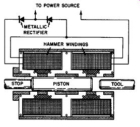
Fig. 14-8. Cutaway Section of an Electric Hammer Designed for Operation
With Metallic Rectifiers.
Electric hammers are somewhat similar to air hammers in design, with a free piston that strikes a positive blow on the shank of the tool being used – 360 degr. blows per minute when operated on a 60 cycle circuit. Fig. 14-8 is a drawing of the hammer, piston, windings, and rectifier circuit connections of the hammer.
The piston is the only working part and is pulled back and forth by two powerful magnets wound around the barrel of the hammer.
The magnets are energized alternately by pulsating currents derived from a metallic rectifier circuit that is a part of the hammer outfit.
Due to the simple magnet principle operated by rectifiers, this type of electric hammer will work continuously through the toughest jobs without breakdown or time out.
Due to the rectifier control, this type of electric hammer is very powerful. It strikes thousands of sharp blows every minute, drilling, cutting, channeling, scaling, bushing, or any of its other uses, and one of these electric hammers will do the work of several men.
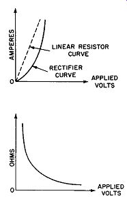
Fig. 14-9. Rectifier Curves. (A) Rectifier and Linear Resistor Curves. (B)
Forward Resistance of a Rectifier.
Metallic Rectifier as Voltage Regulator
The metallic rectifier may be employed in simple circuits to help maintain load voltages more constant. In this application the nonlinear resistance characteristics of the rectifier in the forward direction is utilized. Referring to the voltage-current curve of the metallic rectifier which has been reproduced in Fig. 14-9A, it will be noted that the rectifier does not obey Ohm's law--for if it did, its curve would be linear as represented by the dotted line. However, at any point on the curve the voltage drop across the rectifier divided by the current through the rectifier produces the forward resistance for that operating point.
It is interesting to learn in what manner the rectifier resistance varies. The curve giving this information can be derived from the voltage-current curve of Fig. 14-9A by obtaining its reciprocal. This operation yields the forward resistance curve of the rectifier as shown in Fig. 14-9B or this curve may be obtained experimentally.
It is to be noted that the resistance change is rapid for initial applied voltage changes but that larger values of applied voltage yield almost constant resistance.
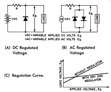
Fig. 14-10. Voltage Regulator Circuits. (A) DC Regulated Voltage (B) AC
Regulated Voltage (C) Regulation Curve.
Taking advantage of this nonlinear resistance property of the metallic rectifier in conjunction with the use of a fixed resistor, circuits may be devised to regulate load voltage for both AC or DC circuits. Fig. 14-10 shows the circuit con figurations and the regulation obtained.
As the applied voltage increases the current increases more rapidly at first because of the nonlinear characteristic of the metallic rectifier; hence a series current-limiting resistor R which absorbs the increasing applied voltage in the form of an IR drop tends to maintain the load voltage more nearly constant.
Since in alternating current circuits the polarity of the load leads periodically reverse, it is necessary to use two rectifier assemblies "back-to-back" to obtain regulation over both parts of the alternation.
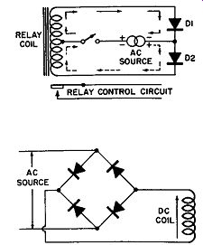
Fig. 14-11. Full-Wave Rectification Without a Transformer.
Fig. 14-12. Conventional Type Coil Used In Relays.
Full-Wave Rectification Without Transformer for Use in Control Circuits
A unique application of a center-tap coil as shown in Fig. 14-11 may be employed in the control of relays and other sole-noid actuated devices whereby full-wave rectification is obtained with half the rectifiers that would be required for operation of a conventional type coil. The conventional type coil and circuit arrangement is shown in Fig. 14-12. In the center tap coil arrangement the coil is wound with a center tap and connected into the circuit so that both halves of the coil winding are additive as shown in Fig. 14-11. During one-half cycle current flows through the upper half of the coil and through rectifier D1 and back to the source as shown by the solid line arrows. When the current reverses polarity current flows (in the direction shown by the dash line arrows) through rectifier D2 thence through the lower half of the coil to the source. A very important feature of the circuit is that this type of relay is highly efficient since the rectifier acts as a shunt on the half of the coil not receiving current thereby permitting its stored up electromagnetic energy to be returned to the circuit as the other coil current is increasing from zero thus preventing the current ever reaching zero during the off half of the cycle.
In certain applications of the center-tap coil arrangement, it may be important that the pull exerted by either of the two coils be exactly equal. In this instance, the conventional type of center-tap coil would not meet this specific requirement be cause the magnetic pull of the two coil halves will not be exactly equal due to the fact that the inner half of the winding (being nearer the core) will have a smaller diameter than the outer half of the coil; therefore, its resistance will be greater and it will pass a smaller current.
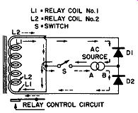
Fig. 14-13. Special Type of Relay Coil to be Used for Full-Wave Rectification.
To overcome the above difficulty the coil may be wound in the manner shown in Fig. 14-13, here the coil is shown as wound of two wires (of the same size) in parallel; therefore, the two coil halves will be exactly equal in length and have exactly the same resistances. The direction of current flow
through this type of coil is shown in Fig. 14-13. When point A of the AC source is positive and point B is negative the current flow through the coil and circuit will be as indicated by the solid line arrows. When the polarity changes so that point B becomes positive then the current flow through the coil and circuit will be as shown by the dash line arrows.