AMAZON multi-meters discounts AMAZON oscilloscope discounts
Physical Outline and Sizes of Rectifier Cells
The metallic rectifier cell has a current rating which is limited by its effective area and by the allowable tempera ture rise. To facilitate the manufacture of rectifier assemblies of various current capacities, the producers of these rectifiers usually standardize on a number of basic rectifier cell sizes.
These basic cell sizes are arbitrary, and one manufacturer's standard need not have any relationship to another producer's basic sizes. The basic rectifier cells may be round, square, or rectangular in outline. The round cells may be available in diameters from tiny disks of 1/32 inch to large cells of 4 3/8 inches in diameter. In the square and rectangular cells the dimensions may start from a square of about one inch to plates 5 x 6 inches or larger. Current ratings depend upon the rectifier type, that is, whether the junction is copper oxide, copper sulphide, or selenium.
Grading of Rectifier Cells
After the rectifier cells are carefully manufactured they are graded according to their forward and reverse resistance and according to the intended circuit application. The grading by forward resistance is the most important, for rectifier cells to be used in parallel must be matched to avoid unequal current flow burdens. This matching is not critical for most applications, especially power rectification, as cells with the lower forward resistance will ultimately match with the other cells as the rectifier assembly ages.
Although it is important to keep the reverse resistance high (the ideal rectifier cell should have infinite resistance), in most applications, low reverse resistance can only produce electrical losses by heating. In half-wave rectifier circuits, of course, the output voltage across the load is a function of the reverse resistance because of the subtracting effect of the reverse current through the load.
In special applications of the rectifier junction, for example, direct current valves, the lowered reverse resistance decreases the efficiency or range of the device.
Only cells of the same size can be connected in series or parallel. Assembly of heterogeneous cells would not be practical in production and would result in unequal current through the cells causing the smaller cells to carry more than their normal load.
Means to Obtain Voltage and Current Ratings Higher Than Cell Rating
To increase the voltage rating of a metallic rectifier the proper number of cells are connected in series; if the assembly is for full-wave or multi-phase operation, then the same number of cells are used in each leg.
To increase the current rating of a rectifier assembly, additional cells are placed in parallel with the identical series parallel arrangement maintained in each leg of a bridge or multi-phase rectifier.
Rectifier cells, then, are assembled in series or parallel in the same manner as dry cells. As an example; five cells, each rated at 26 volts when assembled in series, give the stack a 5 x 26 volts rating or 130 volts. In a like manner, 5 cells each rated at 5 amperes, give the assembly using five of these cells in parallel a 25 ampere rating. In the series example the current rating of the stack remains the same as the original rectifier cell rating, only the voltage rating is increased.
In the parallel example the voltage rating of the stack remains the same as the original rectifier cell rating, only the current rating is increased. When it is desired that both voltage and current ratings of the assembly be increased, it is necessary to use series-parallel arrangements of the rectifier cells.
The Stack Assembly
Rectifier stacks are fabricated of the required number of rectifier cells assembled upon a threaded stud covered with an insulating sleeve. Metal washers space the cells to allow convection or forced- air cooling in one type of the metallic rectifier. In another type, cooling fins are required in the assembly; these cooling fins are simultaneously used as terminals to engage the front and back electrodes of the rectifier cells. Electrical connections to the front and back of the other type of rectifier cells are made by means of terminals extending from the center to beyond the periphery of the cells.
The terminals or the terminal cooling fins are located central ly between the cells and at the end of the stack assembly as required. See Figs. 3-1 and 3-2.
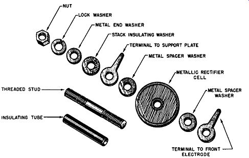
Fig. 3-1. Elements of a Selenium Rectifier Stack Assembly,
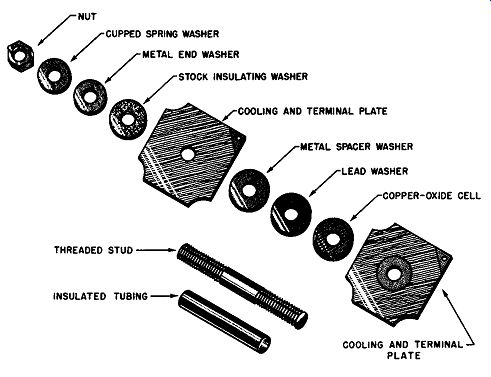
Fig. 3-2. Elements of a Copper-Oxide Rectifier Stack Assembly.
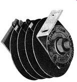
Fig. 3-3. A Full-Wave Bridge Rectifier. 24 volts AC
Input, 0.6 Ampere DC Output. (Courtesy of Seletron Division of Radio Receptor Co., Inc.)
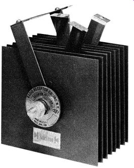
Fig. 3-4. A Single-Phase Full-Wave Bridge Rectifier. Maximum Input 52 Volts
rms. Output 37.8 Volts, 7.5 Amperes, DC. (Courtesy of Seletron Division of
Radio Receptor Co., Inc.)
Spring washers at either end of the assembly keep the stack tightly together and minimize the possibility of damage to the stack due to twisting in handling. In some types of rectifier assemblies (copper-oxide, for example), the spring washers are also required to keep the stack assembly under pressure for electrical reasons to be subsequently discussed.
Figs. 3-3, 3-4, and 3-5 illustrate some examples of rectifier stacks manufactured by the Seletron Division of the Radio Receptor Company of New York. These rectifier stacks use selenium rectifier cells. The full-wave bridge of Fig. 3-3 can be seen to comprise four round cells, one rectifier cell to each leg of the full-wave bridge. This stack arrangement will be described in the section dealing with full-wave rectification.
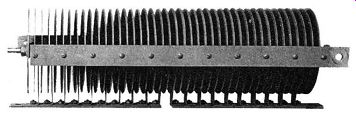
Fig. 3-5. A Center-Tap Type, Full-Wave Rectifier.
24 Volts AC Input, 80 Amperes DC Output. (Courtesy of Seletron-- Radio Receptor Co,, Inc.)
Fig. 3-4 comprises a full-wave bridge having two cells in each leg of the bridge, totaling eight cells for the whole assembly. The cell plates used are 4 1/2 x 5 inches and the complete rectifier weighs one pound and ten ounces.
Fig. 3-5 is a heavy duty, center-tap type full-wave rectifier. The circuit arrangement and details for this type stack will also be described later.
Protective Coatings
Metallic rectifier assemblies require the same care and protection from high humidity, corrosive dust, acid and alkali atmospheres, and fungus conditions as do other types of electrical equipment. To render this protection some kind of finish coating is necessary to cover the rectifier assembly. This coating should be applied at the factory as the finish is no better than the manner in which it is applied and handled after the rectifier assembly is completed.
In general, the finish may consist of a coating of special varnish or paint; this is adequate for stacks not exposed to outside atmospheres. A series of varnish or paint coats will produce a finish able to withstand 50 hours of salt spray test.
This type of coating is recommended for rectifier stacks exposed to high humidity or adverse climatic conditions. Fungicidal ingredients are necessary in these finishes, if the stacks are to be used in tropical climates.
One manufacturer of metallic rectifiers uses multiple coats of a synthetic varnish which is especially adapted for protection against moisture. As an added feature the varnish is colored black to improve the cooling of the rectifier assembly by radiation.
Care must be exercised in handling rectifiers so as not to damage the finish as a bad scratch or crack in it will make the rectifier vulnerable to an attack by the surrounding atmospheric conditions.
One manufacturer suggests that the users of rectifiers refrain from applying ordinary paints or lacquers to the unfinished rectifiers or to abused rectifiers, until they have consulted the supplier. It is possible that the finish to be applied by the user may be destructive if applied directly to the rectifier cells or applied in combination with such finish as is al ready on the plates.
For extreme or special applications it has even been possible to enclose the rectifier assembly in an oil-sealed arrangement.
The above comments apply principally to power rectifier assemblies. Small control or instrument rectifiers may be adequately protected by being hermetically sealed in plastic or electron tube-like structures since the heat dissipation requirements are nil.
Half-Wave Rectifier Circuit
In order to discuss such commercial practices as terminal markings and coding of the rectifier stacks, it is necessary to give a preliminary description of several simple power circuit applications of metallic rectifiers. A more complete discussion of the circuitry involved will be reserved for the section dealing with rectifier circuits.
The chief use of metallic rectifiers is to convert alternating current into direct current; in this conversion when an alternating potential is applied to a circuit containing a rectifier cell in series with a load, current flows when the alter nations are of one polarity; negligible current flows when the alternations are of the opposite polarity. The nomenclature and forward conducting polarity of the rectifier cell is shown in Fig. 3-6.
This rectifier cell employed in a simple circuit with the alternating current source and a resistive load is diagrammed in Fig. 3-7A. The small graphs near the voltage source and adjacent to the load resistor display the waveform of the applied voltage and the resulting unidirectional current flow in the circuit. This simple type of rectifier circuit wherein but half of the input alternation is used is identified as a half-wave rectifier circuit.
The mode of operation of a half-wave rectifier circuit is shown graphically in Fig. 3-7B, where the metallic rectifier cell characteristic has applied to its "input" or vertical axis an alternating potential represented by the sinusoidal waveform A-B-C-D-E-F-G. The projection of this potential curve upon the volt-ampere curve of the rectifier "reflects" on to the horizontal axis the waveform of the resultant current flow. The current flow for the positive alternations is great; the current flow for the negative alternations is almost negligible. The dashed horizontal line through the output current waveform shows the average value of the current flow through the load resistor; that is, it represents the value of direct current flow that a well-damped DC ammeter will indicate.
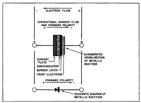
Fig. 3-6. Nomenclature and Forward Polarity of a Half-Wave Rectifier.
(A) Simple, Half-Wave Circuit.
(B) Graphical Representation of Half-Wave Rectifier Performance.
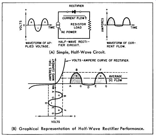
Fig. 3-7. A Half-Wave Rectifier.
Output Terminal Markings
The reader will note that the applied polarity required for forward-direction current conduction is shown in Fig. 3-6.
He then would assume that the terminals of a commercial rectifier would be likewise marked, that is, terminal A marked positive and terminal B marked negative.
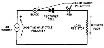
Fig. 3-8. Current Flow and Rectification Polarity Markings.
In commercial practice, however, the opposite is true; terminal A of the rectifier cell is marked negative or painted black, while terminal B is marked positive or painted red.
The reason for this contradiction is that most users of metallic rectifiers are chiefly interested in the device as a power rectifier and desire to know which terminal of the rectifier represents the positive or negative terminal of the rectified output. For example, in Fig. 3-8 the current flow of the half wave rectifier is in the direction of the arrowhead when the applied alternating potential is of the polarity shown. On the opposite alternation of the power source, practically no current flows because of the unidirectional conduction property of the rectifier cell. With such applied input polarity that will cause current flow, the voltage drop across the load is as shown in Fig. 3-8 and is defined by the interpretation of conventional current flow. It can be seen that terminal B is connected to the end of the load resistor which is the positive terminal of the rectified voltage drop, while terminal A (through the alternating power source) is connected to the negative terminal of the rectified voltage drop across the load resistor. Hence, in commercial practice where greater interest is in the sign of the rectified output, terminal B of Fig. 3-6 is marked+ or painted red, while terminal A is marked--or painted black.
These polarity markings may be called rectification polarities of the metallic rectifier cell and are opposite to the forward conduction polarity signs.
In this guide, the commercial polarity markings of the rectifier cell or rectifier assembly will be honored and this system will be identified as the rectification polarity markings. In more complex rectifier stack assemblies where AC terminals are separate from the DC output terminals, the AC input terminals are marked AC or marked with a strip of yellow paint.
Full-Wave Rectifier Circuits (Single-Phase)
Several full-wave, single-phase rectifier circuits will be discussed so that the reader may be better prepared to understand the interpretation of the coding system used by manufacturers which will be described later. To introduce the full-wave circuits more simply we will start with the half wave rectifier circuit discussed previously, only this time we will isolate the rectifier circuit from the source of alternating power by means of a transformer. This circuit is shown in Fig. 3-9; here a transformer is used to couple the primary source of power to the DC load through the half-wave rectifier.
The electrical symbol for the metallic rectifier is used and is represented by the arrowhead and bar combination. By commercial convention in rectifier circuits the bar represents the positive electrode whereas the arrowhead represents the negative electrode.
Fig. 3-9 clearly shows that due to the unilateral valve action of the half-wave metallic rectifier, direct current power is available only for the positive alternations of the AC power source; very little current flows during the negative alternations.
(A) Schematic Diagram (B) Voltage and Current Waveforms.
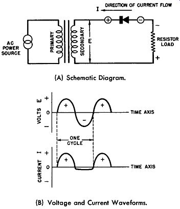
Fig. 3-9. A Half-Wave, Single-Phase Rectifier Circuit.
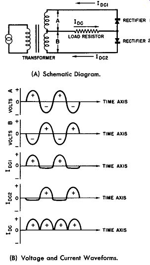
Fig. 3-10. A Single-Phase, Center-Tapped, Full Wave Rectifier Circuit. (A)
Schematic Diagram. (B) Voltage and Current Waveforms.
Frequently, this uneven delivery of DC power is not satisfactory for an application; in this case the circuit of Fig. 3-10 may be used. This circuit is a single-phase, full-wave rectifier circuit using a center-tapped power coupling transformer.
By virtue of the center-tapped construction of the power trans former, two equal and opposite voltages are available with the center tap conductor as a reference; these voltages are A and B. Their time and magnitude relationship are shown graphically in Fig. 3-l0B. Two rectifiers and the common resistive load connected as shown in Fig. 3-10A produce a full-wave direct current delivery to the load. Rectifier 1 delivers a half cycle of direct current on one alternation while rectifier 2 covers the following alternation. Study the curves Ioc1 and Ioc2. The summation of these two currents graphically yields Ioc which is the current flowing through the load resistor.
Frequently, the power conversion application does not justify the cost of the special center-tapped power transformer, yet it is necessary to obtain full-wave operation. This requirement may be met by an arrangement known as the single- phase, full-wave bridge. In this arrangement four half-wave rectifier cells are connected in a manner so as to yield full-wave rectification. The circuit is shown in Fig. 3-11A. When the alternation of the AC power is such that terminal A of the bridge is positive and terminal C is negative, the direction of current flow from the power source is given by the solid arrows.
When the alternation is such that junction C is positive and junction A is negative, the current flow direction is indicated by the dashed arrow lines. It is important to note that although two sets of rectifier cells are used, resulting in two paths of current flow through the legs of the bridge for positive and negative alternations of the power source, the direction of the current flow through the load is unidirectional giving full-wave power to the load. It can be seen that the full-wave bridge rectifier behaves as a synchronous commutator or switching device, electronically converting AC power into DC power.
(A) Schematic Diagram.
(B) Voltage and Current Waveforms.
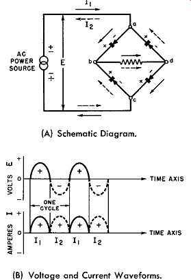
Fig. 3-11. A Single-Phase, Full-Wave, Bridge Rectifier Circuit.
The single-phase, full-wave bridge rectifier circuit of Fig. 3-11 has been redrawn in Fig. 3-12A to show the correct method of wiring the four rectifier cells. As an aid towards this wiring the rectification polarities of each cell are shown as well as the polarity of the rectified power output across the load.
In a commercial stack for a single-phase, full-wave bridge rectifier, the rectifier cells are stacked upon an insulated stud in a columnar manner (see Fig. 3-5); in Fig. 3-12B the schematic diagram of Fig. 3-12A has been rearranged physically to show the stack layout. The schematic diagrams in Figs. 3-12A and 3-12B are electrically equivalent; the cells are identically numbered in each diagram for ease in comparison. Fig. 3-12B also shows the color coding of the AC input and the DC output terminals.
LOAD CURRENT FLOW
(A) Correct Method of Wiring Four Rectifier Cells for Single-Phase, Full-Wave, Bridge Rectification.
(B) Schematic of the Same Full-Wave Bridge Rectifier as Arranged in a Commercial Stack.
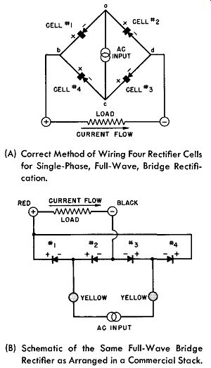
Fig. 3-12. A Single-Phase, Full-Wave, Bridge Rectifier Circuit.
There are two possible arrangements of the rectifier cells upon the insulated stack to make up the single-phase, full-wave rectifier bridge; both arrangements are electrically equivalent and one or the other scheme is used by different manufacturers of rectifiers. To minimize the confusion which might arise over this practice, Fig. 3-13 shows both arrangements with the cell rectification polarities marked. In Fig. 3-13A there is shown the arrangement for the stack assembly in which the outer terminals are positive and strapped together to complete the wiring of the bridge rectifier. In Fig. 3-13B there is shown the arrangement for the stack assembly in which the outer terminals are negative and strapped together to complete the wiring of the bridge rectifier.
(A) A Single-Phase, Full-Wave, Rectifier Bridge Using Four Cells in a Stack Assembly With the Outer Cells Positive and Strapped Together.
(B) A Single-Phase, Full-Wave, Rectifier Bridge Using Four Cells in a Stack Assembly With the Outer Cells Negative and Strapped Together.
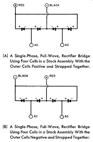
Fig. 3-13. Schematic Diagrams of Commercial Rectifier Stacks.
Thus far, all of the schematic diagrams have shown one cell per leg for the various rectifier arrangements. It was mentioned previously that the rating of a rectifier assembly could be increased by connecting rectifier cells together much as dry cells are connected (in series, parallel, and series parallel) until the desired rating is obtained. The only other condition is that the individual cells have similar voltage and current ratings so as to distribute the load--again identical to dry cell wiring practice.
Fig. 3-14 illustrates three rectifier assemblies having more than one cell per leg. In Fig. 3-14A is illustrated a single-phase, half-wave rectifier consisting of three cells in series; the voltage rating of this assembly is three times the voltage rating of its individual rectifier cells.
In Fig. 3-14B is illustrated a series-parallel arrangement of four rectifier cells wired for half-wave, single-phase rectification. Here the voltage and current rating is double that of the individual cells making up the assembly.
In Fig. 3-14C is illustrated a single-phase, full-wave rectifier bridge having two cells per leg. The voltage rating of this assembly is double that of the bridge shown in Fig. 3-13 which consists of one rectifier cell per leg. Fig. 3-14C is the schematic diagram of the rectifier stack shown in the photograph of Fig. 3-4.
(A) Half-Wove Rectifier-Three Cells in Series. (B) Half-Wave Rectifier-Four Cells in Series Parallel.
(C) Full-Wave Rectifier-Single Phase Bridge With Two Cells in Each Leg.
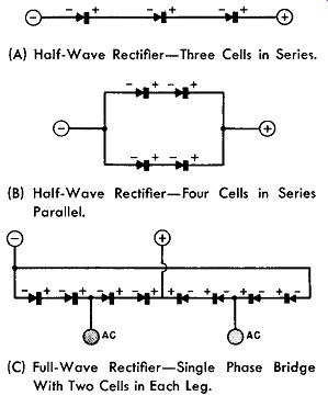
Fig. 3-14. Series Parallel Arrangements of Rectifier Cells.
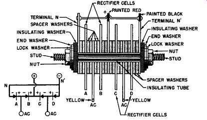
Fig. 3-15. Cross Section of a Commercial, Single Phase, Full-Wave, Rectifier
Bridge Stack Assembly.
The reader having, by this time, been introduced to rectifier cells, stacking arrangements, and stacking components is prepared to more easily understand commercial practice in these matters. In Fig. 3-15 is sketched a cross section of a commercial, single-phase full-wave rectifier bridge stack assembly. For ease in comparison the equivalent schematic diagram of the same arrangement is also shown in this figure and this reveals that the stack has one cell per leg.
Commercial practice in polarity and color marking or coding is also indicated.
Coding of Rectifier Stacks
It has been stated previously in this section that when it is necessary to increase the voltage and/ or current rating of a rectifier, rectifier cells may be assembled in series, parallel, or series-parallel in the same manner as dry cells until the desired rating is achieved. Moreover, rectifier cells may be assembled in half-wave, center-tapped full-wave, full-wave bridge, or in multi-phase arrangements as necessary to meet the requirements.
Furthermore, these rectifier stacks may be assembled from cells whose current carrying capacity may be economically selected; for example, a stack intended for 1/2 ampere capacity may use rectifier cells whose area is two square inches, whereas a stack intended for higher current service may use plates 5 x 6 inches in dimension.
The rectifier stack is marked by its manufacturer's coding system to identify the nature of these variations in the structure. Examples of markings on rectifier stacks from different venders may be listed as follows:
(Federal)
(International)
(Mallory)
(Seletron)
These code markings are arbitrary; there is no standardization in this phase of rectifier business as yet (1956) and each manufacturer has his own code system; hence, the key to the code must be obtained from each specific supplier's catalog if interpretation is desired.
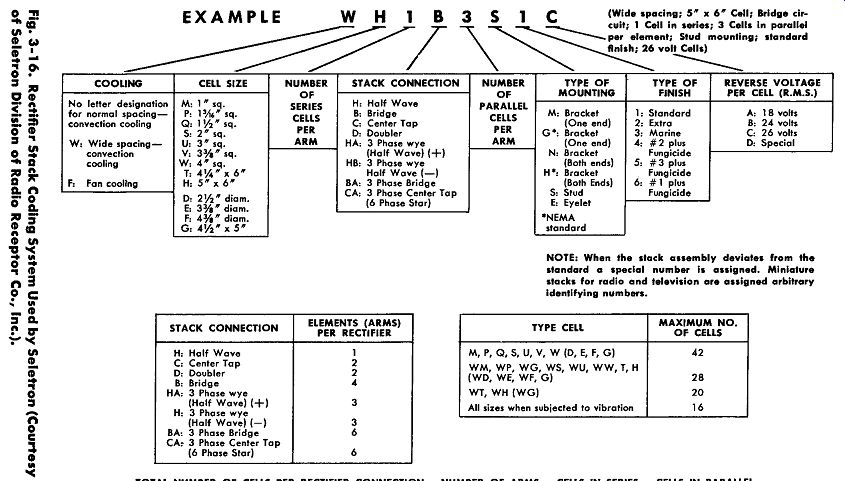
Fig. 3-16--- TOTAL NUMBER OF CELLS PER RECTIFIER CONNECTION--NUMBER OF ARMS
x CELLS IN SERIES x CELLS IN PARALLEL.
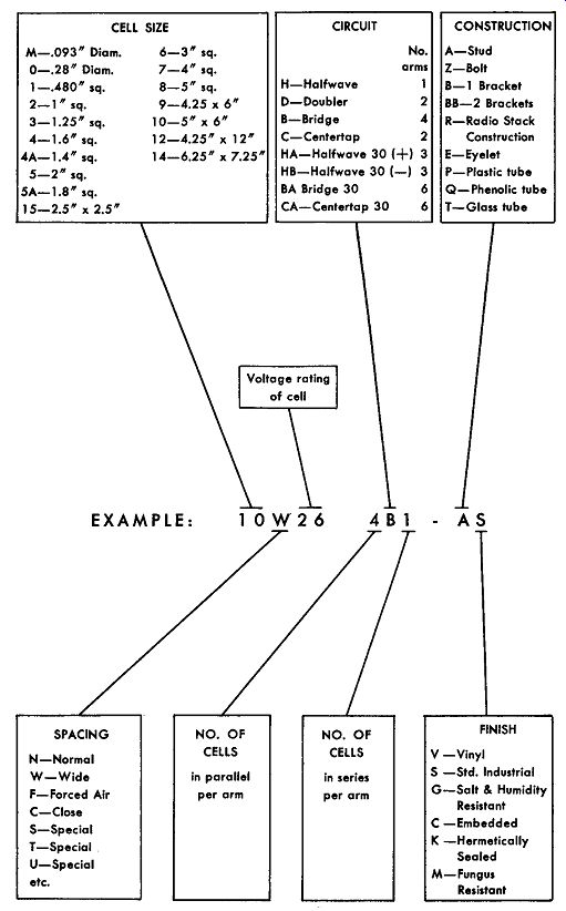
Fig. 3-17. Rectifier Stack Coding System Used by Sarkes Tarzlan (Courtesy
of Sarkes Tarzlan, Inc,),
Two examples of keys to codes of rectifier stacks from commercial suppliers are given; Fig. 3-16 is the key to the code used by the Seletron Division of Radio Receptor Co., N. Y.
Fig. 3-17 shows the key to the code used by Sarkes Tarzian Inc., Bloomington, Ind.
With the aid of its respective key, the code to any rectifier reveals quite completely the stack's electrical and mechanical 'Specifications.
Stock and Custom Rectifier Stacks
Because of the great number of combinations possible, it is very difficult to stock rectifier stacks. The factors involved are voltage ratings, current ratings, whether single phase half-wave or full-wave, or multi-phase half-wave or full-wave, protective coatings, mounting means and others.
Several organizations are stocking and having distributed through the industry rectifier stacks of the more popular type--generally single-phase arrangements. Wherever standard stock rectifiers can be used, some time and expense can be saved in an application. However, most applications require some feature not provided in the standard stack necessitating then a custom assembly from the supplier. This requirement is especially true in connection with the design and development of new products.
Close work with the vender's field or sales engineer is necessary for the custom assembly of rectifier stacks to the customer' s requirement. As a preliminary effort towards obtaining the required rectifier stack most manufacturers require the following information:
Required DC output voltage.
Required DC output current.
Phase of power source.
Voltage variations in power source.
Ambient temperature limits.
Duty cycle.
Nature of load.
Atmospheric conditions.
This information is usually obtained by a questionnaire form supplied by the vender.
Temperature Range of Operation
Selenium and copper oxide rectifiers are usually rated on a basis of 35 degrees Centigrade. Magnesium-copper sulphide rectifiers may be operated at ambient temperatures of 100 degrees Centigrade or higher. If higher than rated temperatures are required, then the rectifier output must be de-rated or forced cooling of the rectifier must be employed. Specific data on each type will be given in its respective sections.
On the low temperature range, rectifiers have been successfully operated at minus 40 degrees Centigrade and lower.