AMAZON multi-meters discounts AMAZON oscilloscope discounts
Introduction
In Section 1 the development of the first dry disc or metallic rectifier was described. This discovery of the rectifying property of the junction between the cuprous oxide and the copper base upon which it was formed, was made in November, 1920, by L.O, Grondahl and P.H. Geiger of Union Switch and Signal Company. The discovery was a by-product of an effort to produce an electrical relay without moving parts or contacts, that is, a device whose impedance or resistance could be easily changed through a large range to simulate the opening and closing of electrical circuits as by relay contacts.
During this study it was found that the resistance of the copper-copper oxide combination was greater in one direction than in the other, and that a high ratio of resistance existed between the forward and reverse directions of current flow. This, as was previously explained, is the property required of a rectifier cell.
While a description for producing the copper-oxide rectifier cell as used in the original experiment was given in Section 1, the past 31 years have seen a great many improvements in the technique of production and in the electrical characteristics of this type of cell. The amazing thing, how ever, is that after all of these years of development and manufacture there still remains many problems, the solutions of which have not been completely determined because there are so many possible combinations of the variables. Some of these problems have to do with the results of varying the amounts and kinds of impurities in the copper base plate, the proper quenching technique, and the exact reason why import copper is superior to domestic copper.
Though a great many refinements for the production of copper-oxide rectifiers have been evolved during the past years, the exact process for manufacturing these rectifier cells differs with the different manufacturers and also depends to some extent upon the ultimate use.
In this guide manufacturing methods for the production of metallic rectifier cells will not be stressed, for certain details are considered trade secrets and besides an itemized account on this subject is beyond the scope of this guide. However, a brief description of the production techniques involved will be described more as an illustration than as an exact, complete, or recommended method.
Production
The basic component of a rectifier assembly is the rectifier cell; this copper-oxide rectifier cell is manufactured from copper imported from Chile. Copper from this source produces more consistent cells--perhaps because of lower impurities and also for other reasons not known. This imported copper undergoes a special rolling process and a surface suitable for polishing is provided. The resulting copper sheet is approximately 0.05 inch thick for the average cell. The copper sheet is then punched in the form of washers or plates with centrally located holes used for mounting purposes.
The next step is to provide a thin film of cuprous-oxide with its attendant outer layer of cupric-oxide on the surface of the copper washer or plate. This is done by heating the copper disc or plate to 1000 degrees Centigrade or to the highest temperature which can be used without deforming the copper pieces because of softening action. The duration of this heating or oxidation period is about ten minutes.
After the surface of the copper piece has been oxidized, it must be brought back to room temperature from the high oxidation temperature. In one practice for producing these cells, another furnace called an annealing furnace is provided into which the rectifier cells are placed from the oxidation process so as to bring them to some predetermined temperature from which to cool or quench them. Since the temperature from which it is cooled and the rate at which it is cooled has a profound effect upon the electrical properties of the rectifier cell. The annealing time as well as the rate of cooling between the oxidizing and the annealing furnace is important.
From the annealing furnace the cells are quickly quenched or cooled in a water bath.
The cupric-oxide layer formed during the cooling of the rectifier cell from the oxidizing temperature has a very high electrical resistance and is not useful in the rectifying property of the copper-oxide cell. This layer is the outer high resistance layer over the cuprous-oxide layer formed upon the copper piece and must be removed. Originally, this black oxide was removed by grinding; later this surface removal was accomplished by sand blasting or by abrasion with emery cloth. Currently, the same task is done chemically through the use of mineral acids which remove this high resistance layer.
The junction between the copper and the cuprous-oxide has the valuable property of permitting the flow of electrons readily from the copper to the oxide and obstructing the flow of electrons in the reverse direction. With the electrical current flow normally defined as from the positive to the negative, this junction will exhibit a high electrical resistance to the flow of current from the copper to the cuprous-oxide and a reasonably low electrical resistance of current flow in the direction of cuprous-oxide to the copper base plate--this constitutes an electrical valve with one-way characteristics.
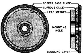
Fig. 4-1. Plan and Exaggerated Cross Sectional View of Copper-Oxide Rectifier
Cell.
To complete the copper-oxide rectifier cell, it is necessary to make electrical contact with the cuprous-oxide surface.
This electrical contact with the cuprous-oxide can be made in a number of suitable ways. One method uses a lead washer or disc which is pressed against the oxide surface with a predetermined pressure. See Fig. 4-1. To prevent the lead disc from reacting with the cuprous-oxide surface and cause an increase in the forward resistance of the rectifier cell, a thin coat of tin may be applied to the lead washer surface, or colloidal carbon in the form of Aquadag can be applied to the cuprous-oxide surface of the cell before assembling the lead washer electrode. In another method a portion of the outer surface of the cuprous-oxide is reduced to copper and a coating of a metallic film, such as nickel, is electrolytically deposited on the oxide surface. Then, this plated film is used as the collector of the electric current over the whole of the oxide surface. See Fig. 4-2 for a plan and cross-sectional sketch of this type of copper-oxide rectifier cell. In another arrangement, especially useful for instrument rectifier applications, electrical contact to the cuprous-oxide surface is provided by an evaporated gold film which has been condensed on this surface.
COPPER BASE PLATE BARRIER LAYER
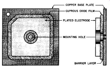
Fig. 4-2. Plan and Exaggerated Cross-Sectional View of Plate Type Copper-Oxide
Rectifier Cell.
It is now apparent that the copper-oxide rectifier cell consists primarily of a cuprous-oxide disc and a metallic disc in good electrical contact. To insure this good, electrical con tact, the cuprous-oxide is formed directly upon the copper washer, disc, or plate as described previously, resulting in a metallic electrode and an oxide member in molecular contact.
When this cell is used in a rectifier assembly, electrical connection to the copper plate is obtained by a connector tab.
Electrical connection with the oxide surface is obtained through the medium of a disc of soft metal, metal foil placed in contact with the oxide surface, or by means of electroplating or condensation of a metallic film.
In any of the arrangements described the blocking or barrier layer is in the junction between the copper-oxide and the base plate of mother copper. How this barrier layer is obtained is explained in a later section.
Construction
The copper-oxide rectifier cells described in the pre ceding constitute half-wave rectifiers. Combinations of these rectifier cells may be assembled as required to obtain rectifier stacks suitable for single and multiphase rectification.
Physically, the elemental rectifier cells may be in the form of discs or plates similar to that shown in Figs. 4-1 and 4-2. (The cross-sectional views in these figures are grossly exaggerated so that the proper layers of the cell can be seen.) In the form of discs, these cells have been produced with diameters from 3/16th inch or less up to 1 1/2 inches. In the form of plates, copper-oxide cells have been produced in sizes approximately 4 inches wide and ranging from 4 to 12 inches in length.
In the plate type, moreover, the copper-oxide cell may be processed with cuprous-oxide on one or both sides. An ex ample of the latter is shown in an exaggerated cross-sectional sketch in Fig. 4-3.
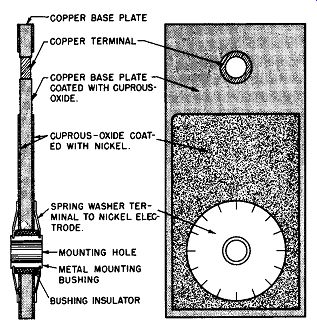
Fig. 4-3. Plan and Exaggerated Cross Sectional View of Plate Type Copper
Oxide Rectifier Cell With the Oxide Coating on Both Sides.
In the disc-type cell stack, the assembly consists of an insulated stud upon which is placed a nut, a spring washer, a pressure washer, an insulating washer, a terminal or cooling fin, a lead washer, a copper-oxide cell, a lead washer, a steel separator (as an optional spacer), a lead washer, a copper oxide cell, etc. The circular spring washers maintain a predetermined pressure upon the stack for normal changes in temperature, while the lead washers are placed between the adjacent current carrying elements to secure uniform electrical contact over the entire surface. In the larger disc type assemblies, cooling fins are used for heat dissipation, for the cell column itself is solid. To obtain greater electrical rating (greater electrical output per cell) spacers are used in the column of the stack to derive optimum cooling fin spacing.
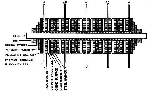
Fig. 4-4. Cutaway View of a Full-Wave, Copper-Oxide Rectifier Stack Assembly.
Electrical connections to the stack are obtained by solder or screw type terminals. Fig. 4-4 shows in cross-sectional detail a copper-oxide stack.
This copper-oxide stack is an assembly of rectifier cells arranged as a full-wave bridge for use in a single-phase circuit.
Each leg of the bridge comprises two cells and each group of two cells is mechanically separated by means of cooling fins which simultaneously act as terminals. Moreover, the cooling fins are suitably spaced by means of spacer washers in the assembly so as to obtain the maximum heat dissipation from the stack.
It will be beneficial for the reader to verify these comments by studying the cutaway view of Fig. 4-4. It will be noted that the cutaway rectifier stack of Fig. 4-4 is similar schematically to the single-phase, full-wave rectifier bridge using four cells in a stack assembly with the outer terminals positive and strapped together as shown in Fig. 3-13A. (In Fig. 4-4 the outer positive terminals are not shown strapped together so as to minimize confusion. Usually the customer does this operation while wiring the rectifier into his circuit.) The chief difference between the two stacks is that in Fig. 4-4 there are two cells in series for each leg of the full-wave bridge.
In the assembly of the plate cell rectifiers, the stacks comprise an insulated stud upon which are mounted an end plate, a spring or lock washer, an insulating washer, a terminal, a rectifier cell, a brass or micarta spacer, a rectifier cell, etc. The plate cells are used in rectifier assemblies with the larger electrical ratings. The space between the plates lends the arrangement ease towards forced draft cooling (fan cooled assemblies). Of course, plate rows are also sup plied as self-cooled units.
In either the disc or plate type of rectifier stack, the copper-oxide assembly is protected from humidity and corrosive dust and atmospheric conditions by several coats of insulating varnishes.
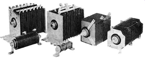
Fig. 4-5. Examples of Disc and Plate Type Copper-Oxide Rectifier Stacks
Made by the General Electric Co. (Courtesy of General Electric Co.)
Commercial examples of both the disc and plate type of copper-oxide rectifiers are shown in Fig. 4-5.
(A) Exaggerated Cross-Sectional View of Generalized Metallic Rectifier Cell.
FORWARD DIRECTION
(B) Symbol for Metallic Rectifier Cell.
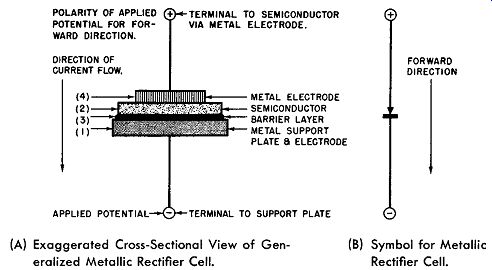
Fig. 4-6. Generalized Metallic Rectifier Cell
Elements of the Copper-Oxide Rectifier Cell
At the beginning of this section it was briefly described how a copper-oxide rectifier cell may be produced. To better understand this cell and to be able to clearly visualize its elements, it is necessary to review the material in Section 2.
Here a metallic rectifier cell was represented by the generalized rectifier cell and shown to comprise four essential components. This generalized metallic rectifier cell is repeated in Fig. 4-6 where Fig. 4-6A represents an exaggerated cross sectional view of the rectifier cell and Fig. 4-6B represents the electrical symbol for the rectifier cell. The four essential elements of this generalized metallic rectifier cell are:
1. A metal support plate which does not enter into the rectification process but provides a mechanically strong and stable platform for the rest of the rectifier cell and serves as one of its terminals.
2. A semiconductor layer the nature of which depends upon the specific rectifier type.
3. A barrier, blocking, or insulating layer which is formed electrically or by heat treatment.
4. A metal electrode which makes intimate electrical contact with the barrier layer (if of the selenium type) or with the semiconductor (if of the copper-oxide type) by plating, metallic spraying, carbon film, or mechanical pressure.
It will be recalled from the comments in Section 2, that the pertinent structure of the metallic rectifier cell is a semi conductor layer separated from a metal electrode by an extremely thin insulating or barrier layer. The opposite surface of the semiconductor is in electrical contact with a low resistance metal plate which does not function in the rectification act except as an electrode. Moreover, the position of the barrier layer determines the forward direction of the rectifier cell--the direction in which substantial current flow occurs when the applied polarizing potential is directed from the semiconductor to the adjacent metal electrode across the barrier layer.
(A) Exaggerated Cross Sectional View of Rectifier Cell.
(B) Schematic Diagram Showing Rectification Polarity Markings.
(C) Exaggerated Cross Sectional View of Stack Assembly of Half-Wave Rectifier.
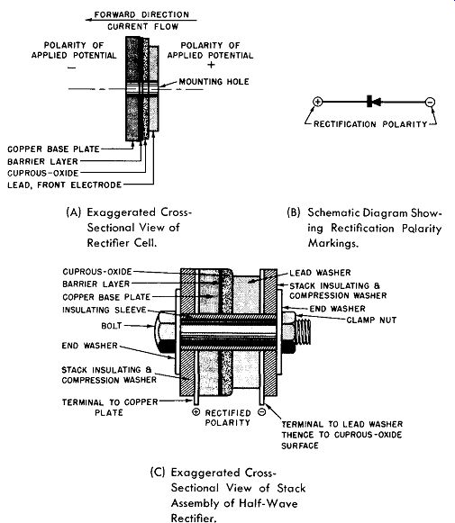
Fig. 4-7. The Copper-Oxide Rectifier Cell.
How then does this description of the generalized rectifier cell apply to the copper-oxide cell discussed previously? It was shown that the copper-oxide rectifier cell consists of a "pure" copper disc or plate upon which a layer of cuprous oxide is formed by oxidation at a high temperature. The subsequent quench from the annealing temperature causes the oxide to freeze with occasional copper ions missing from the oxide crystals leaving an oxide with an excess of oxygen. At the junction between the copper base plate and the oxide, however, where the copper is rich, a very thin layer of cuprous-oxide remains practically perfect in its crystal structure. Thus is obtained a pure copper metal separated from cuprous-oxide containing an excess of oxygen by a very thin layer of perfect cuprous-oxide. The perfect oxide is inherently an insulator, while the oxide with the excess of oxygen is a semiconductor.
Hence, the essential structure of the copper-oxide cell con forms with the generalized metallic rectifier cell as comprising a semiconductor separated from a metal electrode by a thin insulating layer. The rectifier cell is completed by means of an auxiliary metal electrode contacting the free surface of the semiconductor. Current flows readily when the base plate is made negative with respect to the oxide, while practically no current flows when the applied potential is reversed.
In Fig. 4-7A the generalized metallic rectifier cell as exemplified by the copper-oxide type is specified. The forward direction as previously defined is also shown. In Fig. 4-7B the electrical symbol for this rectifier cell is shown. The arrow head points towards the forward direction; however, when the cell is used as a rectifier the rectification polarities are as shown here (see Section 3). Fig. 4-7C illustrates how the copper-oxide cell may be assembled to make a practical half-wave rectifier. Of course, having available copper-oxide rectifier cells, one is not limited to half-wave rectifiers but may assemble any suitable combination to meet the requirements. A few such assemblies were described in Section 3.
For purposes of comparing the various types of rectifier cells and to achieve simplification of presentation of their characteristics, it is desirable to describe these properties in terms of the basic rectifier cells. This is the approach used in this and the following three sections.
Volt-Ampere Characteristic
The volt-ampere graph shows the relationship between the applied voltage and the resultant current flow. The experimental method for obtaining this information was described in Section 2. The resulting graph for a copper-oxide rectifier cell is given in Fig. 4-8. This is the characteristic curve which will be obtained for a typical copper-oxide rectifier cell having an effective area of one square inch. The electrical symbol for the rectifier cell is given with the polarity of the applied potential shown for the forward and reverse direction characteristics. It will be recalled that the applied potential for the forward direction (the direction in which the current flows readily through the cell) is that potential applied from the semiconductor to the adjacent metal electrode across the barrier layer with the semiconductor polarized positive and the metal electrode polarized negative.
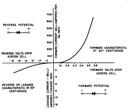
Fig. 4-8. Volt-Ampere Characteristics of Copper Oxide Cell at 20° C.
Since but a fraction of a volt is required to pass full rated current in the forward direction, the horizontal axis of the graph of Fig. 4-8 is plotted in tenths of volts in the for ward direction. The resultant current is plotted in units of 100 milliamperes per square inch.
In the reverse direction a rather large applied voltage is required even for a small flow of current--the leakage current. Hence, the horizontal axis to the left of the vertical current axis of the graph is plotted in volts. Note that the resultant leakage current as measured by the vertical axis below the horizontal voltage axis is plotted in milliamperes, that is, this scale has been expanded 50 times so that the shape of the leakage characteristic can be clearly shown. If this scale had not been expanded, the leakage current curve would have appeared as a horizontal line, practically coinciding with the horizontal axis.
The voltage applied in the conducting or forward direction is plotted against the resultant current in tenths of volts against units of 100 milliamperes per square inch to facilitate comparison with other type rectifier cells in later sections.
The volt-ampere curve of the copper-oxide rectifier cell demonstrates that the current flow in the forward direction is at least 1000 to 2000 times greater than the current flow in the reverse or leakage direction. For example, a forward or con ducting voltage drop across the rectifier cell of about 0.5 volt at 20 degrees Centigrade results in approximately 0.4 ampere per square inch current flow as seen in Fig. 4-8. For the same applied voltage in the reverse or blocking direction, only a fraction of a milliampere per square inch flows through the same copper-oxide rectifier cell at the same temperature.
The non-linear property of the copper-oxide rectifier is also clearly seen from a study of Fig. 4-8. For as the applied voltage is increased from zero in the forward or conducting direction, the current through the rectifier cell in creases quite slowly at first. (As an example, for the first 0.1 volt increase the resultant current change is but a few milli amperes.) Then, the rate of current increase becomes quite rapid with the increasing applied voltage and approaches a linear characteristic for the larger increments of applied forward voltage.
In the reverse direction the applied voltage must be in creased to large values before even milliampere values of current flow.
In the forward direction the maximum applied voltage (voltage drop across the cell) is limited by the maximum rated current flow which is based mainly upon the effective rectifier cell area and the permissible temperature at which the rectifying junction is to operate.
In the reverse direction the maximum applied voltage across the rectifier junction is limited by the breakdown across the barrier layer when the potential gradient becomes too great.
When such a breakdown occurs, the cell junction is no longer effective as a rectifier and symmetrical current flow results.
The forward and reverse characteristics of the copper oxide rectifier cell are a function of the ambient temperature which will be described later. For this discussion the ambient temperature is taken as 20 degrees Centigrade or 68 degrees Fahrenheit. In the graph of Fig. 4-8 the electrical symbols in the forward and reverse portions of the characteristic show the polarity of the applied voltage to the rectifier cell for the respective characteristic displayed.
It can be seen from Fig. 4-8 that approximately 1 ampere of current flows through the copper-oxide rectifier cell having an effective area of one square inch for an applied voltage of about 0.6 volt.
When the applied voltage is reversed it is an important property of the rectifier cell to block or hold to a minimum value the reverse current flow. Again from the graph of Fig. 4-8 it can be seen that, for the given ambient temperature, an applied reverse voltage of 10 volts causes a current flow of but 2 milliamperes.
Temperature Characteristic
The temperature of a copper-oxide rectifier cell has a profound effect upon its electrical properties. A quick means of discerning the overall effect of the cell temperature is to study cell volt-ampere characteristics at various temperatures. Such a set of curves is given in Fig. 4-9.
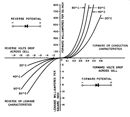
Fig. 4-9. Volt-Ampere Characteristics of Copper Oxide Cell Versus Temperature.
It will be observed from the family of volt-ampere curves for the copper-oxide rectifier cell that the forward and blocking or reverse resistance decrease with increasing cell temperature; that is, the copper-oxide rectifier cell can be considered as a resistive device having a negative temperature coefficient of resistance. As a resistive device the copper-oxide rectifier cell will have a voltage drop across it when it is a part of an electrical circuit. This forward resistance results in a certain amount of heating, the dissipation of which determines the electrical capacity of the rectifier. This heating is the result of I^2R losses in the conducting direction as well as the losses resulting from leakage during the blocking cycle. Most copper-oxide rectifiers are designed to operate at rated electrical capacity for an ambient temperature of 35 degrees Centigrade (98 degrees Fahrenheit). This allows for a temperature rise for the rectifier of 10 to 15 degrees Centigrade above the ambient or a maximum rectifier temperature of about 60 degrees Centigrade. The 80 degree Centigrade curve in Fig. 4-9 is beyond the rating for copper-oxide rectifiers and is given to illustrate the effects of temperature in an exaggerated manner.
It will be noted from the curves of Fig. 4-9 that the for ward characteristics of the rectifier improve with temperature, for, since the forward resistance decreases, less voltage drop is required across the cell to maintain a given current flow. However, the net gain due to the temperature rise is not to the good, for, by examining the negative characteristics versus the cell temperature, the reader finds that the leakage current increases rapidly with temperature. This leakage current, being in the opposite direction to that of the forward current in a rectifier application, reduces the rectification ratio or efficiency of the rectifier. Since operating the rectifier cell beyond its given rating also causes temperature rise in the cell, the curves of Fig. 4-9 graphically show why it is desirable to operate the cells within the ratings assigned by the manufacturer.
Another graphical method to illustrate the volt-ampere characteristic change for different temperatures of the rectifier cell is given in Fig. 4-10. Here the DC volts drop across the cell versus the cell temperature is plotted for three values of constant direct current in the forward direction only. This again shows the large variation in forward resistance of the copper-oxide cell with temperature. In many rectifier applications this variation of forward resistance with temperature is not important. However, in applications of the copper-oxide rectifier where a wide variation in temperature is anticipated, the forward resistance change may have to be considered and compensated. One way to accomplish this is to have the external resistance of the circuit about 10 times greater than the forward resistance of the copper-oxide rectifier at 35 degrees Centigrade. Of course, this larger external resistance swamps out the smaller variation of circuit resistance due to temperature effects upon the copper-oxide rectifier.
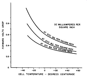
Fig. 4-10. Temperature Characteristics of Copper-Oxide In Forward Direction.
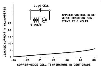
Fig. 4-11. Temperature Characteristics of Copper-Oxide Cell In Blocking
Direction.
Another approach towards compensation of the tempera ture effect of the copper-oxide rectifier takes advantage of the fact that the temperature characteristic of this rectifier is negative (that is, its resistance decreases with increasing temperature), while the temperature characteristic of copper wire is positive. Thus, where the electrical load of the copper oxide rectifier is copper--electromagnets, solenoids, motor fields, etc.--the rectifier and load resistance changes are in opposite directions and tend to cancel.
The leakage current resulting during the blocking or reverse applied voltage also varies with temperature and a typical graph, obtained experimentally, is shown in Fig. 4-11.
Voltage-Resistance Characteristic
The general shape of the resistance-voltage curve of a copper-oxide rectifier cell is given in Fig.4-12. This graph shows that, as the applied voltages approach zero, the forward and reverse direction resistance approach each other in ohmic value. In the forward or low resistance direction and at low values of voltages, the resistance decreases approximately exponentially as the applied voltage increases; at higher for ward voltages, the forward resistance becomes nearly constant and low in ohmic value.
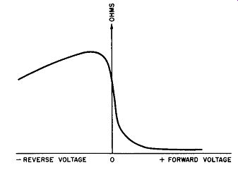
Fig. 4-12. Voltage-Resistance Graph for Copper-Oxide Rectifier Cell.
In the reverse direction the resistance increases with the increasing applied voltage up to a very high ohmic value at about 1 1/2 volts; beyond this voltage, the resistance decreases with the increasing voltage at a rate which is nearly linear. If this reverse voltage is increased too far, a break down of the rectification junction takes place.
Voltage Rating of the Cell
Voltage rating of a rectifier cell is defined as the root mean-square value of the AC voltage applied to the cell.
Copper-oxide rectifier cells are generally operated at voltages ranging from 2 to 10 volts rms with 8 volts being the average. Beyond 8 volts the leakage current tends to increase rather rapidly, thus, in effect, a metallic rectifier cell is generally rated by the voltage it will practically withstand in the reverse or high resistance direction.
Current Rating of the Cell
The current rating of a rectifier cell is the maximum current that may be passed through it in the forward or low resistance direction within its thermal rating. It is expressed as average DC amperes as read on a D' Arsonval type ammeter. For the copper-oxide type rectifier the current rating is approximately 1/10 ampere DC per square inch at 35 degrees Centigrade for a self cooled stack (no cooling fins). Current rating is dependent upon stack design and the cooling methods employed.
Voltage Regulation
Copper-oxide rectifier cells are resistive devises and as such have appreciable voltage regulation. Voltage regulation is defined as the ratio of the difference between the out put voltage at full load and at no load to the full load voltage in percent, thus:
= No load Voltage- Full load voltage X 100%
Voltage Regulation Full load Voltage
This difference between the no-load and the full-load voltage is the potential drop across the rectifier cell in the forward direction.
As an example, if the no-load voltage is 9 volts and the full-load voltage is 6 volts, there is a 3-volt drop across this fictitious rectifier cell and its voltage regulation is 50%, for:
9-6 Voltage Regulation=-
6
- X 100% = 50%.
For the general purpose copper-oxide rectifier cell the voltage regulation is of the order of 15 to 25%. A typical voltage regulation curve for a copper-oxide rectifier cell is shown in Fig. 4-13. In Fig. 4-14 is displayed a family of voltage regulation curves for a single-phase, full-wave bridge, copper oxide rectifier supplying a resistive load.
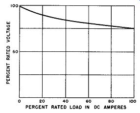
Fig. 4-13. Voltage Regulation Curve of a Typical Copper-Oxide Rectifier
Cell.
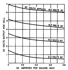
Fig. 4-14. Voltage Regulation for a Single-Phase, Full-Wave Bridge, Copper
Oxide Rectifier Supplying a Resistive Load.
When a single, fixed load is connected to a rectifier, the voltage regulation of the rectifier may not be important. When more than one load is connected to the rectifier, the application should be checked to verify that under minimum load conditions the resultant higher voltage will not destroy or damage the load device. Also in applications which involve short-time current output in excess of the rectifier rating, the application should be checked to insure that under maximum load conditions the voltage is not too low for successful operation of the load device.
Efficiency
Efficiency or the conversion ratio of a metallic rectifier is defined as: Average DC volts output x average DC amperes output l00% AC watts input x This may be expressed as the ratio, in percent, of the DC volt amperes output (average values) to the AC watts input. The efficiency of copper-oxide rectifier cells average somewhere between 60 and 85% depending upon the type of circuit and the rating and operating conditions of the particular rectifier. In a single-phase, full-wave circuit connected to a resistive load, the rectifier stack efficiency at rated load will be from 60 to 65 percent. In a similar circuit with a battery charging load, the efficiency may be from 70 to 75 percent. In three-phase operations 85 percent efficiency is achieved at full-rated output. At low temperatures the efficiency will be slightly less than normal, while at higher operating temperatures the efficiency will be increased somewhat due to the lowering of the internal resistance of the rectifier.
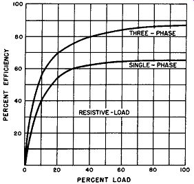
Fig. 4-15. Efficiency of Single-and Three Phase, Full-Wave Bridge, Copper-Oxide
Rectifier Supplying a Resistive Load.
Typical efficiency graphs are shown in Fig. 4-15 for single-and three-phase rectifier stacks supplying resistive loads.
Power Factor Power factor, the ratio in percent of the AC watts out put to the AC volt-ampere input is practically unity for a copper-oxide rectifier at power frequencies because this type of rectifier is a resistive device. The overall power factor is determined by the associated equipment in the rectifier circuit such as the transformer, ventilating fans if used, and the nature of the load. When the rectifier is used in a circuit with a transformer and connected to a normal load such as a resistance device or batteries, the power factor is usually 95 percent or better.
Frequency Characteristics
The majority of past and present applications of copper oxide rectifier cells and stack assemblies have been for rectification or control of power frequencies ranging from 25 to 60 cycles per second. For this reason the frequency characteristics of the rectifier have not been too important because of the low frequencies involved. It is believed that most copper oxide rectifier stacks will operate satisfactorily up to about 1000 cycles per second. Beyond this frequency inherent capacitance effects seriously reduce the performance of this type of rectifier. Since the copper-oxide rectifier cell consists primarily of two electrodes separated by an insulating layer, it can be seen that there exists a capacitance effect which becomes active at the higher frequencies. This inherent capacitance of the copper-oxide rectifier cells is similar in its behavior to a small capacitor in parallel to an ideal rectifier cell. The adverse performance caused by this shunting capacitor is to reduce the impedance of the rectifier cell in the reverse direction and, hence, to cause a marked reduction in the efficiency or conversion ratio of the cell as the frequency of the applied voltage is increased beyond, say, 1000 cycles per second.
The value of this "shunting" capacitance is a function of the effective area of the rectifier cell and also depends to some extent upon the strength of the polarizing voltage applied across the cell.
For instrument and control applications it is often necessary to operate small current copper-oxide rectifiers at frequencies almost up to the megacycle range. In this case it is necessary to employ special techniques in the processing of these rectifier cells and, more important, to severely re duce the area of the working surface so as to minimize the shunting capacitance.
Speed of Operation
The copper-oxide rectifier does not deteriorate when not in operation; no electroforming period is required though the rectifier may have been out of circuit and operation for years. Thus, this type of rectifier is always ready to function with rated characteristics as soon as the power is applied.
Effect of Idleness When a copper-oxide rectifier is idle its reverse resistance tends to increase. The forward resistance will also increase by an amount that is a function of temperature at which the cell or stack is maintained.
At 10 degrees Centigrade for example there will be no change in the forward resistance. (Note: increases in the re verse direction are beneficial while increases in the forward resistance reduce efficiency.) At 25 degrees Centigrade the forward resistance will increase about 10% in a year's time.
Aging and Life---Another copper-oxide rectifier characteristic is referred to as aging. Aging is defined as an increase in the resistance of a copper-oxide cell or stack with time. This change in the rectifier resistance with time is reflected in the output of the cell or stack and can be illustrated by Fig. 4-16. This shows that, in order to maintain a constant DC output, the AC input must be gradually increased during the first 6 to 12 months. There is no run-away tendency pf this aging condition and the characteristic becomes stabilized after the initial aging period.
Because of this aging characteristic of copper-oxide rectifier cells and stacks, designs using these rectifiers are customarily provided with tapped transformers having adequate aging taps to permit adjustment of the input AC so as to maintain the DC output voltage constant. Thus, it is possible to increase the AC voltage input to overcome the increased rectifier resistance over the first 6 or more months of operation time. After this initial readjustment is completed there is no further need for additional input changes as the output has stabilized--provided that the rectifier temperature and electrical ratings are not exceeded.
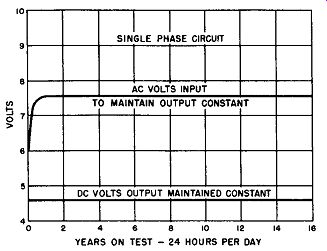
Fig. 4-16. Aging of Copper-Oxide Rectifiers-Continuous Life Test.
The forward aging shows up as an increase in the for ward resistance, the amount of increase being a function only of time and stack temperature. Forward aging has no effect on stack ratings as all ratings are based on aged characteristics.
A good average allowance for forward aging is 15 per cent, so the transformer range for full load in the aged condition should provide a voltage tap 15 percent greater than the initial tap.
Copper-oxide rectifiers have been used for many years for the charging of fire alarm and railway signal batteries, switchgear control batteries, for DC supply to passenger elevator control circuits, and many other applications where reliability is of great importance; copper-oxide rectifiers in stalled more than twenty years ago continue to give dependable service. Long experience has demonstrated that when this type of rectifier is properly applied it has an indefinite life.
Threshold Voltage
In some types of metallic rectifiers it is necessary to apply a certain minimum voltage before conduction in the forward direction takes place. If the applied voltage is alternating, then a certain minimum value must be applied before rectification takes place; that is, in either the direct or alternating voltage application, conduction does not initiate for values of voltage below a critical voltage identified as the threshold voltage.
The copper-oxide rectifier cell or stack does not exhibit threshold voltage effects, thus making it particularly useful for instrument and control applications.
Operating Temperature and Derating
Copper-oxide rectifier cells and stacks are thermally rated so that the voltage and current ratings specified will not cause I^2R losses resulting in excessive operating temperatures. These electrical losses causing the heating of the cell or stack are due to two effects--forward resistance producing an m drop, and reverse resistance producing leakage current under the influence of the reverse voltage. In the ordinary operating temperature ranges, all metallic rectifiers exhibit a negative temperature coefficient of forward resistance.
Hence, at any given output current, forward loss drops with rising operating temperature. Leakage current follows a pattern dependent upon temperature and back voltage. The final operating temperature is governed by the choice of voltage and current rating and the heat dissipation design of the stack structure.
The standard electrical rating for the rectifier cell or stack is based on a maximum ambient temperature of 35 degrees Centigrade (98 degrees Fahrenheit). This ambient temperature is the temperature of the air surrounding or moving past the rectifier and need not be the same as the room temperature.
When this ambient temperature of operation exceeds 35 degrees Centigrade, the rectifier losses must be reduced so that the operating temperature does not exceed the safe maximum. To accomplish this reduction of rectifier losses, it is necessary to derate the output voltage rating and, hence, the AC input voltage in proportion to the increase in the temperature over 35 degrees Centigrade. When thus derated the applied reverse voltage is now less than the maximum permitted so the current rating or the forward current can remain the same as at 35 degrees Centigrade or be somewhat higher.
Fig. 4-17 shows a curve for de rating the output voltage rating of the copper-oxide rectifier to the proper values for higher ambient temperatures. For example, for service at 50 degrees Centigrade ambient temperature, the DC output voltage rating of the copper-oxide cell or stack must be de rated to 70% of normal voltage. Thus, a 50 volt, 1 ampere normal rating must be reduced to 35 volts, 1 ampere for the new operating temperature of 50 degrees Centigrade. No de rating of the current is required.
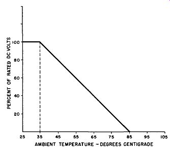
Fig. 4-17. Voltage De-rating for High Ambient Temperatures. No De-rating
of Output Current.
It is interesting to note from Fig. 4-17 that for an ambient temperature of about 85 degrees Centigrade the copper oxide rectifier has been derated to an output voltage of zero.
Safe operation at that temperature is not possible.
Ambient Conditions Other Than Temperature
Though copper-oxide rectifier cells and stacks are fairly robust and immune to normal ambient conditions, they may be adversely affected when exposed to excessive humidity, corrosive vapors, fumes, or dust. For average applications the stacks are treated with special varnishes or similar protective coatings. In especially severe applications the rectifier stacks may be immersed in oil or even hermetically sealed.
Future Outlook
Of the three types of metallic rectifiers the copper-oxide type has had the longest history of useful application and development. Electrical capacities range from milliwatts up to 100 kilowatts output.
Because of the present military requirements of low weight, compactness, and operation at high voltage per cell and high operating temperatures, none of which is well filled by the copper-oxide rectifier, there is no anticipation of startling improvements or development work in this type of rectifier.