AMAZON multi-meters discounts AMAZON oscilloscope discounts
All electronic components are capacitive; however, a capacitive component is defined as one in which capacitive reactance is its dominant parameter. Beginners are often confused by the term capacitive reactance. However, the principle of capacitive reactance is basically very simple. Consider a long, small diameter pipe that is bent in a circle and connected in series with a water pump. The water pump in hydraulic theory is analogous to a battery in electronic theory. Pressure must be applied to force water around the pipe "circuit," because the small bore of the pipe imposes hydraulic friction; in an electronic circuit, a small wire similarly imposes resistance to electron flow.
CAPACITIVE REACTANCE
Proceeding to the concept of capacitive reactance, suppose that a rubber diaphragm is now inserted in the pipe to oppose water flow. Now, the water which is urged forward by pump pressure encounters an additional type of resistance. The diaphragm stretches and exerts a backward pressure against the pump. When the diaphragm is stretched to the point where the back pressure equals the pump pressure, the water flow stops.
In electronics, we would say that the capacitor is charged-its back electric force equals the battery voltage.
Evidently, if the pump is valved out of the pipe line and the two ends of the pipe are connected with a bypass pipe (short circuited ), the diaphragm relaxes and causes water to flow through the pipe in a reverse direction to establish equilibrium.
In an equivalent electronic circuit, the charged capacitor has been short-circuited and thereby discharged.
The important point here is that capacitive reactance (the stretched diaphragm) opposes current flow (water flow) by storing energy (back force of the stretched diaphragm). Conversely, resistance dissipates energy and when water is forced to flow through a small pipe, the losses due to friction are converted to heat. Likewise, when electrons are forced to flow through a small wire, the wire becomes hot.
When a diaphragm is stretched, or a capacitor is charged, no energy is dissipated-the energy is simply stored, and it can be recovered when the circuit conditions are appropriate.
It should be remembered that reactance stores energy, and resistance dissipates energy. However, since reactance opposes current flow, this opposition like resistance is also measured in ohms. Ohm's law states that I = E/Xc, where Xc is the capacitive reactance in ohms. The reactance of a capacitor is equal to 1/2 pi fC ohms, which shows that capacitive reactance varies inversely with frequency. It is meaningless to state the reactance in ohms of a capacitor, unless the frequency of measurement is given.
VOLTAGE-CURRENT RELATIONSHIP
This writer has spent many hours with various apprentices, explaining how and why the current leads the voltage in a capacitive circuit. The best way to clarify this fact seems to be a continuation of the water analogy discussed above. In other words, consider a water-pipe circuit containing a pump and a rubber diaphragm. When the pump is first started, the diaphragm offers no opposition because it is not stretched. The stretch is zero, or, the "voltage" across the diaphragm is zero.
Yet water is rushing rapidly against the diaphragm, and it could be said that the "current" is large when the pump is first started.
The water flow then begins to slow, because the diaphragm is being stretched and is opposing the water flow. Plainly, the diaphragm "voltage" is increasing, while the "current" is decreasing. Finally, the diaphragm becomes so stretched that the water flow stops. The current is then zero, but the "voltage" of the stretched diaphragm has increased to a maximum. To summarize briefly, current maximum corresponds to voltage zero; current medium corresponds to voltage medium; current zero corresponds to voltage maximum. This is simply another way of saying that current and voltage are 90° out of phase.
Is the current leading the voltage in the pipe circuit ? Of course it is-the water current has its maximum speed of flow before the diaphragm voltage rises to its maximum value. This hydraulic analogy shows how current leads the voltage in a capacitive circuit. On the other hand, current is always in step with the voltage in a resistive circuit. Now, the fact that current in a capacitive circuit is 90° out of phase with current in a resistive circuit illustrates another vital principle : resistive ohms and capacitive ohms must be added at 90°, or, they must be added at right angles.
IMPEDANCE
Imagine a circuit consisting of a 100-ohm resistor in series with a capacitor that has a reactance of 100 ohms at the operating or test frequency. A right triangle must be drawn, with the base equal to the altitude. The base represents the 100-ohm resistance, and the altitude equals the 100-ohm reactance. The hypotenuse of the triangle then represents the impedance of the RC circuit. The hypotenuse has a length which represents the impedance of the circuit, and this impedance is evidently 141 ohms (approximately) . Ohm's law states that 1= E/Z, where Z is the impedance of the circuit.
With this basic understanding of the electrical action in a capacitive circuit, it is simple to understand how capacitance values are measured and how capacitive components are tested.
Different methods are employed to test various types of capacitive components, but all are based fundamentally on the principle of capacitive reactance.
OUT-of-CIRCUIT CAPACITOR TESTS
A good capacitor has a rated value of capacitance, within a specified tolerance. When it is suspected that a capacitor is off value, technicians often replace it without testing. However, some technicians prefer to test capacitors. Testing is sometimes mandatory when a suitable replacement is not available for substitution. Several instruments are useful for measuring capacitance values. Your choice will depend on shop instrumentation as well as personal preference.
Capacitance Measurement With RC Bridge
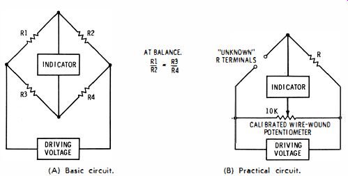
Fig. 1. A Wheatstone bridge. (A) Basic circuit. (B) Practical circuit.
The most common instrument employed to measure capacitance in both service shops and labs is the RC bridge. This is basically a Wheatstone bridge, the operating principle of which, is shown in Fig. 1A. In service-type instruments, an eye tube is generally used as a null indicator ; lab-type bridges employ a galvanometer, which is more sensitive. In either case, the indicator reads zero when the bridge is adjusted for balance. As depicted in Fig. 1B, a potentiometer with a calibrated dial is generally used to directly indicate the value of the unknown capacitor.
The Wheatstone bridge circuit shown in Fig. 1B is used to measure unknown resistance values. The better bridges can indicate resistance values more accurately than an ohmmeter.
The general principle of the Wheatstone bridge is also used to measure capacitance values when the instrument is switched to its capacitance ranges. As depicted in Fig. 2A, two of the bridge arms now consist of capacitors. One is a standard or reference capacitor inside the instrument. The other is the unknown capacitor connected to the external terminals of the bridge. A potentiometer with ' a calibrated dial is customarily used to directly indicate the capacitance value at balance (Fig. 2B)_
Test Voltage in the Bridge
An AC driving voltage is necessarily used to drive a capacitor bridge, since capacitance values are measured on the basis of capacitive reactance. On the other hand, a Wheatstone bridge might be driven by either AC or DC voltage. In general, it is desirable to drive a Wheatstone bridge with DC, because a resistance measurement can then be made in the presence of reactance.
Service-type capacitor bridges are usually driven by 60 cycle AC. However, lab-type bridges are generally driven by 1,000 -hz AC. A typical service-type bridge applies up to 50 volts across the capacitor under test. This value is well within the working-voltage range of paper, mica, and ceramic capacitors. On high-capacitance ranges used for testing electrolytic capacitors, the bridge ordinarily applies less voltage across the "unknown" capacitor-a value of three volts rms is typical. Inasmuch as the peak voltage could exceed the rating of some electrolytic capacitors used in transistor circuitry, it is evident that this danger must be kept in mind.
It is easy to check the voltage applied across an unknown capacitor. Simply connect a VTVM across the capacitor under test-if the applied voltage is excessive, turn off the bridge immediately to avoid damage to the capacitor. With the advent of electrolytic capacitors rated at low working voltages, service type bridges have become available which apply a maximum of 0.5 volt to the capacitor under test.

Fig. 2. RC bridge used to measure capacitor values. (A) Basic circuitry
of an RF bridge. (B) Typical instrument configuration.
Measuring Small Capacitance Values
Service-type bridges commonly have a lower limit of 10 mmf, although some instruments measure capacitance values as small as 1 mmf. Obviously, if it were attempted to use test leads when measuring small capacitances, the stray capacitance of the leads would introduce a large error. Therefore, small capacitors should be connected directly to the instrument terminals. Test leads also tend to pick up stray hum which can mask the null indication.
Sensitivity of Null Indication
The bridge dial can be set accurately only if the null indication is sensitive, to give a sharp indication of balance. Sensitivity is increased if higher driving voltage is applied to the bridge. On the other hand, high test voltages must not be applied to low-rated capacitors. Therefore, other means are employed when it is necessary, to obtain adequate sensitivity.
For example, one manufacturer utilizes an amplifier for the eye tube, as seen in Fig. 3. The amplifier provides a sensitive null indication, although the test voltage applied is less than 0.5 volt rms. R42 provides adjustment of sensitivity.
Courtesy Sprague Electric Co.
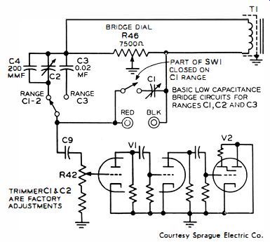
Fig. 3. Amplifier increases the null indicator sensitivity.
It is interesting to note that if you wish to rework an older type capacitor bridge, this can easily be accomplished. It is only necessary to reduce the test voltage by means of a voltage divider and to increase the indication sensitivity. The easiest way to increase the sensitivity is to remove the eye tube, and insert a pair of scope leads into the input (grid and cathode ) terminals of the socket. A scope has comparatively high vertical sensitivity, and gives a sharp null indication although the test voltage is quite low.
Test of Leakage Resistance
A defective paper, mica, or ceramic capacitor might be open, or it may have lost a substantial portion of its rated capacitance. This defect shows up as a subnormal reading on the capacitance dial. Also, a defective capacitor can have the correct capacitance but exhibit objectionable leakage. When the leakage is substantial, a complete null cannot be obtained. Or, if the capacitor is practically shorted, even a partial null will not occur.
Moderate leakage does not affect the capacitance test, and a defective capacitor would be passed as good unless a supplementary leakage test is made. The simpler types of capacitor bridges test for leakage by applying an adjustable DC voltage to the capacitor. The test voltage is typically adjustable from 0 to 500 volts. In any event, the rated working voltage of the capacitor should not be exceeded. If the capacitor has excessive leakage, the eye tube closes somewhat. A shorted capacitor closes the eye completely. Of course, this type of test does not tell you the value of the leakage resistance. If you want to determine its value, note the extent to which the eye is closed in the leakage test. Then remove the capacitor, and connect various high-value resistors in its stead. When you match the original eye opening, the value of the resistor is equal to the leakage resistance of the capacitor.
A few service-type capacitor bridges have an ohmmeter indication in addition to an eye tube. The ohmmeter operates typically at 25 volts DC. Leakage resistances up to 20,000 megohms are indicated on the calibrated ohmmeter scale. This test can be used on all fixed capacitors that have a rated working voltage of 25 volts, or higher. But you might run into a ceramic capacitor rated at 3 volts. In this case, the test voltage is set to rated value, and the leakage current measured on the meter. The leakage resistance is then calculated from Ohm's law: V = IR.
Power Factor
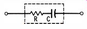
Fig. 4. Series resistance increases power· factor value.
Service-type bridges do not provide measurement of power factor for paper, film, paper-film, mica, and ceramic capacitors.
The reason for this omission is that small fixed capacitors rarely become defective due to high power factor. The only exception might be found when there is a poor internal contact to the capacitor electrodes. This effectively places resistance in series with the capacitance, as depicted in Fig. 4, and raises the power-factor value.
On the rare off-chance that this defect might exist in a small fixed capacitor, the capacitor bridge would probably pass the capacitor as being good. For example, the contact resistance must exceed 50K before the defect is apparent on a typical service bridge. Then, it will show up as an incomplete null-the eye tube does not open up as wide as for a normal capacitor.
However, lab-type bridges that operate at 1 khz can weed out the rare cases in which a small fixed capacitor has an appreciable power factor.
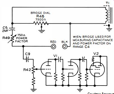
Fig. 5. Circuitry of an electrolytic capacitor bridge.
Electrolytic Capacitors
Although conventional electrolytic capacitors are used in pulsating-DC circuits only (DC with an AC component), it is common practice to measure electrolytic capacitance with an AC bridge at comparatively low voltage. Unlike paper capacitors, electrolytic capacitors generally have an appreciable power factor. Hence, bridges provide for its measurement. A typical configuration is depicted in Fig. 5. Rheostat R49 is connected in series with the standard capacitor C5. A calibrated dial for R49 provides direct reading of power-factor values.
Recall that a power factor greater than zero occurs when there is effective resistance in series with the capacitor under test (Fig. 4) . A complete null in the Fig. 5 configuration can be obtained only when R49 is adjusted to have the same resistance as the effective series resistance in the capacitor under test. Thus, both R46 and R49 must be adjusted for final balance. Then, the R46 dial reads the capacitance value, and the R49 dial reads the power factor.
Meaning of Power Factor
Just what is a power factor? Consider a 25-mfd electrolytic capacitor that has an excessively high power factor. It has an effective series resistance, say, of 60 ohms. At 60 cycles, a capacitance of 25 mfd has a reactance of 100 ohms, approximately. The reactance, Xc is equal to ½ pi fC, where pi is 3.14, and C is the capacitance in farads. Now, the power factor is defined as resistance divided by impedance. Resistance and reactance combine at right angles, as shown in Fig. 6. In this example, the impedance will be 116.6 ohms. Accordingly, the power factor is equal to 60/116.6, or about 5091 0. A power factor might have any value from zero to 100%.
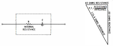
Fig. 6. Power factor defined as resistance divided by impedance.
Of course, the power factor would be different at some other frequency than 60 cycles. The reactance of the capacitor will be less at a higher frequency, such as 1 khz. In turn, the impedance will also be less, and the power factor will be greater.
Evidently, it is meaningless to state the power factor of an electrolytic capacitor by itself; you must also note the frequency at which the power factor was measured. The only exception is when the capacitor has zero effective series resistance. Then, its power factor is zero at any frequency.
Leakage in Electrolytic Capacitors
A defective electrolytic capacitor often has leakage resistance. Unlike the situation depicted in Fig. 6, the leakage resistance is in shunt to the capacitor. Or, the leakage resistance acts as shown in Fig. 7. The leakage resistance is measured on a DC test as previously explained for small fixed capacitors. However, you must be careful to polarize the electrolytic capacitor correctly, because the leakage is commonly checked at the full rated working voltage.
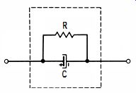
Fig. 7. Resistor R represents leakage resistance of capacitor C.
Appreciable leakage resistance will result in incorrect readings of both capacitance and power factor. Hence, it is advisable to check an electrolytic capacitor for leakage first. If leakage is excessive, reject the capacitor without making further tests. If the leakage is satisfactorily low, proceed to check out the electrolytic capacitor for its capacitance value and power factor.
Ohmmeter Test of Leakage
A limited test for leakage in an electrolytic capacitor can be made with an ohmmeter. Since as the leakage is usually greater at rated working voltage than at a low voltage, the resistance reading of the ohmmeter is not conclusive. Of course, if an electrolytic capacitor should show substantial leakage on an ohmmeter test, it should be rejected. An ohmmeter test is time consuming because it takes a long time for a large electrolytic capacitor to reach full charge through an ohmmeter circuit.
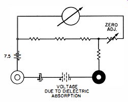
Fig. 8. Nature of dielectric-absorption voltage.
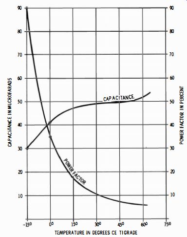
Fig. 9. Temperature coefficient of an electrolytic capacitor.
Dielectric absorption imposes another difficulty. Fig. 8 illustrates the nature of dielectric absorption. If an electrolytic capacitor is charged, and its terminals are then short-circuited, it might be supposed that all the charge is drained out of the capacitor. On the contrary, if the capacitor is allowed to stand open-circuited for a short time after the short-circuit is removed, a DC-voltage measurement will show that due to di-electric absorption a charge has built up.
In an ohmmeter test situation, any dielectric-absorption voltage adds to or subtracts from the ohmmeter battery voltage, thereby giving a false resistance reading. The reading will "crawl" as the dielectric absorption voltage gradually diminishes via the ohmmeter load. This annoyance occurs when an electrolytic capacitor is disconnected from a receiver for test; it also occurs when the capacitor has no residual absorption (has been short-circuited for a long time) if you switch ranges on the ohmmeter.
Temperature Coefficient of Electrolytic Capacitors
Capacitance and power factor of electrolytic capacitors varies with temperature, as illustrated for a typical capacitor in Fig. 9. Capacitance increases with temperature, and the power factor improves. On the other hand, leakage ordinarily becomes greater as the temperature rises (Fig. 10 ). Clearly, you should test electrolytic capacitors at their ambient operating temperature in the receiver.
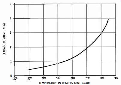
Fig. 10. Leakage current at rated working voltage for a typical electrolytic
capacitor.
Temperature Effects
A small fixed capacitor might have a positive, negative, or zero temperature coefficient. If the temperature coefficient is positive, the capacitance increases with temperature. A negative temperature coefficient causes its capacitance to decrease with increasing temperature. Again, the capacitance change may be cyclic or non-cyclic. A negative temperature-coefficient capacitor is carefully designed to have a cyclic coefficient, meaning that it will return to its original value when the temperature returns to its initial value. Capacitors with almost zero temperature coefficient are commonly called temperature-stable capacitors.
Defective capacitors which are thermally unstable change value objectionably, and often erratically, when subjected to heating and cooling cycles. If they are tested on a capacitor bridge, the null-point drifts when the pigtail is heated with a soldering gun. Such capacitors are definitely defective and should be rejected. If moderate heat does not cause a change in the capacitance value, a capacitor can still be mechanically faulty ; it is good practice to tap the capacitor sharply while observing the null indication. Also, a chill spray can be used for further tests of thermal instability.
Leakage resistance commonly becomes lower when a capacitor is heated. If you raise the temperature of a moderately leaky capacitor on a bridge test, it will often become excessively leaky until it cools off again to room temperature. Sometimes the change is non-cyclic, and the capacitor remains at its low value of leakage resistance. A capacitor which appears to be normal at room temperature can give a "bad" indication on the leakage test when its temperature is increased by 50 or 75 degrees.
Courtesy Arkay International, Inc.
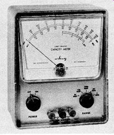
Fig. 11. A typical capacitance meter.
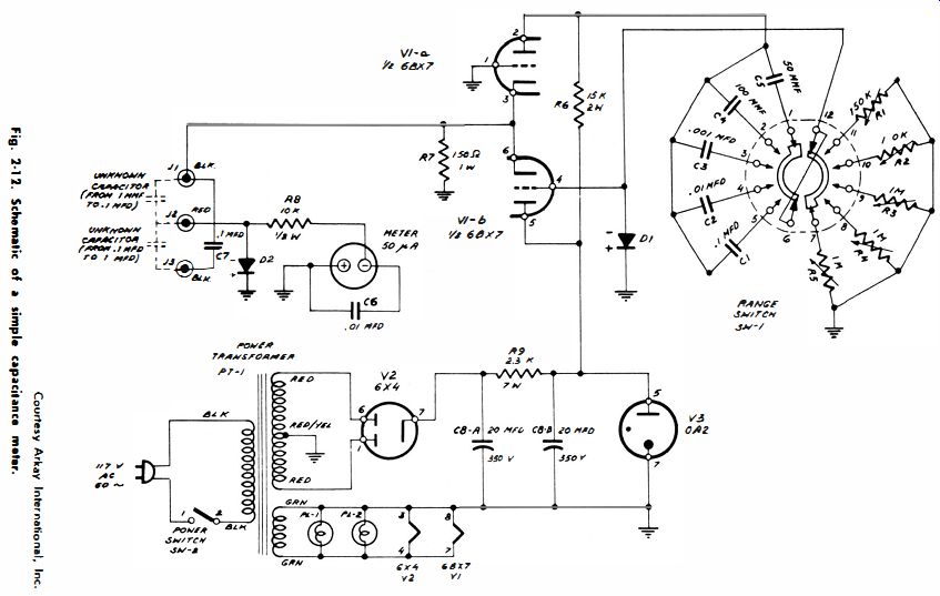
Fig. 12.
CAPACITANCE METERS
Capacitance meters are easier to use than bridges because no null adjustment is required. A capacitance meter such as illustrated in Fig. 11 operates in the same manner as an ohm meter. You will find a few VTVM's which also have capacitance scales. There are two chief types of capacitance meters. One type operates from the 60 -hz line frequency while the other type operates from a wide range of frequencies generated by a built-in oscillator. A high test frequency permits measurement of small capacitance values, typically as small as 1 mmf.
Regardless of the test frequency employed, capacitance meters measure the AC that flows through the capacitor. Ohm's law for AC states that I = E/Xc, where Xc is the reactance of the capacitor. Since X,. = 1/2 pi fC, current flow I = 2 pi CE, which means that if the capacitance is doubled the current also doubles. The circuit diagram for a simple capacitance meter is seen in Fig. 12. Its principle of operation is evident from the functional schematic shown in Fig. 13. The oscillator is a cathode-coupled multivibrator. Its operating frequency depends on the values of C and R. Output is taken from the cathode circuit and applied across the capacitor under test in series with the meter rectifier. The amount of current flowing through the meter circuit is proportional to the value of the capacitor under test.
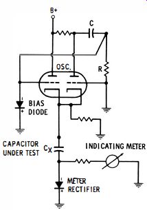
Fig. 13. Basic capacitance meter circuit.
This type of capacitance meter does not check for leakage.
However, more elaborate capacitance meters have a DC meg-ohmmeter function for measuring leakage. A typical instrument tests all capacitors for leakage at 200 volts, and measures up to 1,000 megohms. Since the test voltage applied across the capacitor is not adjustable in this instance, the capacitor must have a rating of at least 200 working volts. Otherwise, it would be subject to damage in the leakage test.
VOM as Capacitance Meter
A rough test of the comparative capacitance of paper capacitors can be made with a VOM by means of the test method depicted in Fig. 14. In this example, the VOM has a sensitivity of 1,000 ohms per volt on its AC voltage ranges. Pointer deflection is proportional to current flow through the capacitor, or, larger capacitance values produce a greater pointer deflection. Before making a capacitance measurement the capacitor should first be tested for leakage. If it is leaky, it should be immediately rejected. In any case the VOM range switch should first be set to read line voltage (117 volts) . If, for example, the capacitor is shorted, the meter reads the line voltage.
In case a small pointer deflection is observed, it is then safe to switch the VOM to a lower range. Capacitance measurements are made on the 10-volt range for the Fig. 14 configuration. Table 2-1 shows the approximate readings that will be obtained in testing capacitance values from 0.001 to 1 mfd.
(This test method must not be attempted on any electrolytic capacitor.)
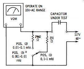
Fig. 14. VOM utilized as capacitance meter.
If no pointer deflection is observed, the capacitor is open.
Note that open capacitors can often be found on an ohmmeter test. The ohmmeter must have a polarity-reversing switch. Set the ohmmeter to its highest range, such as R x 10,000. Connect the capacitor to the test leads. If any steady pointer deflection takes place, the capacitor is leaky and should be rejected. If the pointer rests at infinity, you can proceed to an open test.
Flip the polarity-reversing switch. If there is no pointer deflection, the capacitor is open. A ballistic deflection occurs if the capacitor has appreciable capacitance. A ballistic test can be made down to 0.01 mfd on a typical VOM. VTVM's seldom provide for reversal of ohmmeter polarity.
However, an external DPDT switch can be used for this purpose. It might be installed as a test jig on the service bench.
Since a VTVM is much more sensitive than a VOM, you can make ballistic tests of comparatively small capacitance values.
The VTVM is also a much more sensitive indicator of leakage.
QUICK TEST OF CAPACITOR LEAKAGE
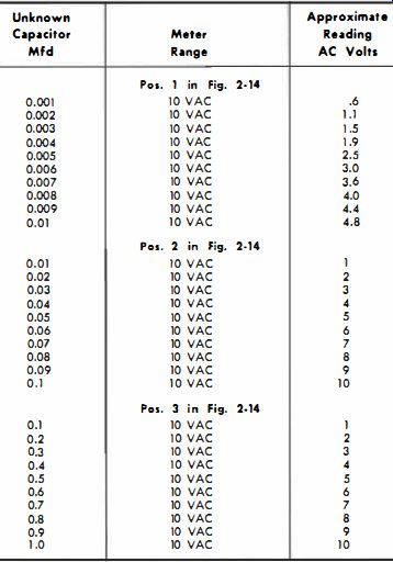
Table 1. Readings Obtained in VOM Capacitance Test
It is often handy to make quick tests for leaky capacitors.
One method is to charge the suspected capacitor from the B+ line. Wait a few seconds and short-circuit the capacitor. If there is no spark, the capacitor is very leaky or shorted and should be rejected. To test for high values of leakage resistance, observe how long the capacitor will hold a charge. The way in which a charged capacitor discharges through its leakage resistance is seen in Fig. 15. This is an exponential discharge--the discharge is fast at first and then slows down as the charge diminishes. The time constant of a leaky capacitor is equal to its capacitance in farads times its leakage resistance in ohms.
For example, a 0.25-mfd capacitor with a leakage resistance of 10 megohms has a time-constant of 2.5 seconds. This means, in practical terms, that the voltage of the capacitor will decay to 37 % of its original value in 2.5 seconds. To put it another way, if you charge this capacitor to 100 volts and then allow it to stand open-circuited, its voltage will fall to 37 volts in 2.5 seconds. This test is not useful on small-value capacitors.
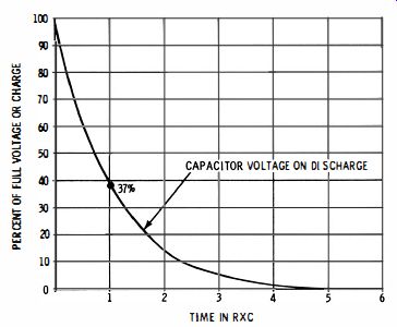
Fig. 15. Exponential curve of a capacitor discharging.
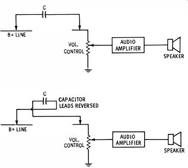
Fig. 16. If C is open, there is no click from the speaker in either the
first or the second test.
Another type of quick test is depicted in Fig. 16. The speaker in the radio or TV receiver being repaired serves as an indicator. It permits quick tests of comparatively small values of capacitors. When the capacitor under test is connected between the B+ line and the input to the audio amplifier, no click will be heard from the speaker if the capacitor is open. But if you hear a click, the capacitor is not open. As you make and break the circuit, a click might be heard every time ; in this case the capacitor is leaky. But if no click is heard on successive contacts, even after several seconds of waiting between contacts, the capacitor is holding its charge. To cross-check, reverse the capacitor leads, as shown in Fig. 16. With a good capacitor, you should hear a click each time a reversal test is made.
IN-CIRCUIT CAPACITOR TESTS
When it is practical to do so, an in-circuit capacitor test is desirable because the capacitor does not have to be disconnected from its associated circuitry. There are various types of in-circuit capacitor testers available. One of these is simply ...
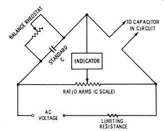
Fig. 17. Bridge for measuring capacitance shunted by resistance.
... designed to measure the value of a capacitor, although shunted by some arbitrary amount of circuit resistance. The principle of the test is depicted in Fig. 2-17. This is a parallel RC bridge.
It differs from an ordinary capacitance bridge in that a balance rheostat is provided across the standard capacitor in the bridge. When the test leads are connected across a capacitor shunted by circuit resistance, the balance rheostat permits a null-adjustment in conjunction with the ratio-arm adjustment.
The ratio arms are comprised of a precision wirewound potentiometer, with a scale calibrated in capacitance values. The indicator is commonly an eye tube. A complete null is obtained only when the balance rheostat is correctly adjusted and the potentiometer also correctly adjusted. An accurate reading of the capacitance value is then obtained. The chief limitation occurs when the capacitor under test is shunted by a low value of circuit resistance. Then, most of the test current flows through the shunt resistance and it is difficult to find a null on the potentiometer. This limitation can be minimized by operating the bridge at higher frequency.
In-Circuit Open and Short Quick Tests
Technicians often work against the clock and prefer to make preliminary quick tests of suspected open or shorted capacitors in operating circuits when it is possible. A coupling, decoupling, or bypass capacitor can be tested for an open simply by bridging it with a good capacitor. Then if circuit operation returns to normal, the conclusion is clear. The bridging test is useful to localize leaky filter capacitors in power supplies, as well as loss of capacitance. For example, when ripple voltage is excessive, it might be due either to loss of filter capacitance or a reduced time constant due to leakage. In either situation the defective filter capacitor can often be localized by bridging with a good electrolytic capacitor. The greatest reduction in ripple voltage is expected when the defective capacitor is bridged. Heat may also be a useful clue-a leaky electrolytic capacitor often runs hot. Likewise, a screen resistor runs too hot if the screen-bypass capacitor is leaking badly.
Suspected shorted capacitors can sometimes be localized by a short-circuit test. For example, consider an overload symptom which you think may be caused by a shorted cathode-bypass capacitor. Simply short out the suspected capacitor, and observe the change in receiver response, if any. A change in picture or sound reproduction shows that the capacitor is not shorted. If there is no change in response it could be due to a short in the capacitor.
VTVM In-Circuit Tests
To check for leaky in-circuit capacitors, various test methods have been devised. A VTVM may often serve as an in-circuit leakage tester for coupling capacitors. The basis of the VTVM test is seen in Fig. 18. With the receiver operating, B+ voltage is usually present on one side of a coupling capacitor, and normally there is very little or no voltage present on the other side. Hence, if C (Fig. 2-18 ), has appreciable leakage resistance RL, a small (or sometimes large) current will flow through grid resistor R. This current flow produces across the grid resistor a voltage drop which is indicated by the VTVM. An objection to this simple method is that small grid currents in tubes sometimes suggest a false conclusion concerning capacitor condition. This objection can be overcome in a parallel-heater system by unplugging the tube ; in a series heater system it is also possible to unplug the tube, provided semiconductor rectifiers are used in the power supply. But if the power supply employs a rectifier tube in the heater string, heater continuity must be maintained by some means. Either a dummy tube must be used (grid pin cut-off), or possibly the heater terminals in the socket could be jumpered.
When the tube cannot be simply unplugged, less time may be consumed by disconnecting one end of the capacitor and making a conventional leakage test as shown in Fig. 19. A VTVM ohmmeter is not an ideal function for a coupling capacitor leakage test because the operating voltage is usually only 1.5 volts, whereas the plate voltage in the receiver might be 150 volts or more. Thus, the test depicted in Fig. 19 is approximately 100 times more sensitive than a VTVM ohmmeter test.
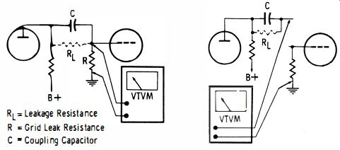
Fig. 18. Test for leakage current.
Three-Lead In-Circuit Tests

Fig. 19. Sensitive leakage test.
To facilitate in-circuit test for leakage of coupling capacitors, manufacturers have developed an instrument that operates on the principle depicted in Fig. 2-20. Three test leads are used. One lead applies approximately 100 volts DC to the plate side of the coupling capacitor C; the second lead connects to ground or B- in the receiver, and the third lead is connected across the grid-leak resistance R. The test is made with the receiver "dead." Hence, no grid-current problem can be encountered. An eye tube is used as the indicator and leakage current through RL causes the eye to open. With average values of grid-leak resistances this type of test will indicate leakage resistance as high as 50 megohms.
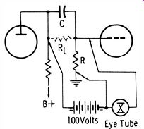
Fig. 20. Basic three lead in circuit leakage test.
Sometimes this form of test is provided as a function of a more complex capacitor tester, as illustrated in Fig. 21. In this case, a meter is used as an indicator of leakage, instead of an eye tube, and comparatively high values of leakage resistance can be detected. However, it is evident that the meter must indicate on the basis of a Good-Bad scale, since the value of the grid-leak resistance is arbitrary. This makes it impossible to calibrate the meter scale accurately in resistance values for in-circuit tests.
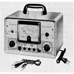
Fig. 21. Capacitor tester using a three lead test.
Open-and-Short In-Circuit Tests
A much more difficult test problem is presented by capacitors that are shunted by resistance in-circuit. This is the situation encountered with plate-bypass, screen-decoupling, and AGC delay capacitors for example. The leakage resistance RL of the capacitor (Fig. 22) is directly shunted by the circuit resistance so that a three-lead test cannot be made. In-circuit tests are usually restricted to detection of dead-shorted and open-circuited capacitors. Most of the two-lead, in-circuit capacitor testers in present use operate with this restriction.
This type of instrument operates at RF and provides separate tests for open-circuited and short-circuited capacitors.
The principle of the open-circuit test is seen in Fig. 23. A 6C4 oscillator which operates at approximately 20 mhz is used.
The test cable with the loading coil (L) represents a quarter wave line at the operating frequency. Hence, a short at the output end of the cable will be reflected back as an open circuit at the input end (and vice versa).
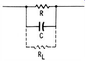
Fig. 22. The value of RL when C is shunted by R i. a difficult test.
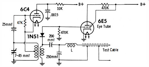
Fig. 23. Basic circuit for the "opens" test in the RF type checker.
The RF voltage at the input end of the cable is rectified by the crystal diode and applied to the eye tube which is normally open. When the test leads are applied across an open capacitor, the terminal conditions for the cable are essentially unchanged, and the eye remains open. However, a capacitor with appreciable capacitance has extremely low reactance at 20 mhz; this is reflected as a high reactance to the input end of the quarter-wave line. In turn the eye tube is driven by appreciable DC voltage, and the eye closes in proportion to the capacitance value.
A capacitance greater than 20 mmf closes the eye completely in a typical instrument. Somewhat smaller values of capacitance produce a partial closure of the eye. Again, the chief limitation in this test is imposed by small values of shunt resistance. When the shunt resistance is less than 50 ohms an open capacitor will seem to test good. Inasmuch as higher values of shunt resistance tend to produce partial closure of the eye, the instrument cannot be used to measure or estimate capacitance values.
The principle of the short-circuit test is depicted in Fig. 24.
The 6.3-volt 60-hz, AC source voltage serves to keep the eye normally closed. Note that if the test leads are shorted together, the bias on the 6E5 grid is "killed," which causes the eye to open. Leaky capacitors cannot be detected by this test, inasmuch as practically a dead short is necessary to open the eye.
Moreover, shunt resistance of 20 ohms or less will open the eye and mask the test. Likewise, very large electrolytic capacitors (2,000 mfd or greater) cannot be tested because their normal reactance is practically a short circuit. Intermittent capacitors can sometimes be picked up on the permissible tests by tapping which may cause the eye tube to flicker.
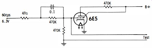
Fig. 24. A shorted capacitor kills the bin on the 6E5 and opens the eye.
Borderline Test
In-circuit tests of borderline capacitors that have a poor life expectancy are made by a pulsing technique. This function is provided by the instrument illustrated in Fig. 21. The pulsing test will detect capacitors which are sufficiently leaky that they would be "caught" by a VOM ohmmeter if an out-of-circuit leakage test were made. The principle of the test is shown in Fig. 25. A 1000-volt DC source is used to charge up a 1-mfd capacitor that periodically discharges through a thyratron tube, thereby generating a sharp pulse voltage.
The test voltage applied by the pulse is determined by adjusting the grid bias on the thyratron, as required. The pulse waveform is developed across a 600-ohm resistor. It is effectively an AC pulse with an average value of zero. The pulse current flows through a 50 u-a DC meter to the hot test lead.
The meter is practically completely bypassed for AC. It will not deflect unless a DC component is generated during the in-circuit test. Note that when the test leads are connected across a resistor no pointer deflection occurs in most cases ; however, if the resistance has a very low value the pointer will tend to oscillate the scale.
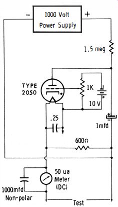
Fig. 25. Working voltage pulse test circuit.
In application, a DC component flows in the meter circuit when the test leads are connected across a borderline capacitor.
In this instance, the comparatively low leakage resistance between the capacitor electrodes tends to break down at the peak voltage of the pulse. Disproportional current, which indicates partial rectification, flows on the peaks. In turn, the pointer deflects on the meter scale. A good capacitor will with stand at least 50 % overload on a pulse test, without developing a detectable DC component. The question is sometimes asked why a pulse waveform is best adapted to this test ; the reason is that comparatively little power is dissipated by the shunting resistance at the peak voltage of a narrow pulse.
In turn, circuit resistors are not heated appreciably, even though the test might employ several hundred peak volts.
Just as pulse tests cannot advantageously be made across low values of shunt resistance, neither can capacitors which are shunted by inductance be tested. One end of the capacitor must be disconnected and an out-of-circuit test made. Pulse tests are unsuitable for electrolytic capacitors because there is an inherent rectifying action that falsifies the test indication. You will find that if you apply an AC voltage to an electrolytic capacitor, such as 3 volts in a capacitor-bridge test, a DC voltmeter connected across the capacitor will show that partial rectification is occurring.
Input Capacitance of Scope
Measuring the input capacitance of a scope is easily accomplished by means of the test shown in Fig. 26. An audio oscillator and a trimmer capacitor are utilized. The trimmer is connected in series between the vertical-input terminal of the scope and audio oscillator. The audio oscillator is set to a fairly high frequency, such as 100 khz. The trimmer capacitor is short-circuited in the first part of the test, and the vertical deflection is noted on the scope screen.
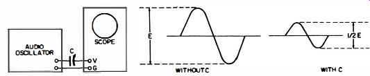
Fig. 26. Measuring input capacitance of an oscilloscope.
Next, the short circuit is removed from the trimmer capacitor, and the trimmer is adjusted to obtain one-half of the original deflection. Finally, the trimmer is disconnected, and its capacitance is measured on a capacitor bridge or meter. The value thus measured is the input capacitance of the scope. This test is based on the fact that a scope input resistance is very high and can be neglected with respect to the reactance of the input capacitance at 100 khz. For example, a capacitance of 25 mmf has a reactance of about 60K at 100 khz, whereas the input resistance of the scope will be 1 megohm or even higher. Thus, the input resistance introduces negligible error into the measurement.
The input capacitor (blocking capacitor) of an AC scope can be easily quick-checked for leakage. A source of 300 or 400 volts DC is desirable, such as from the low-voltage power supply in the scope or from a radio or TV receiver. Apply the DC voltage to the vertical-input terminal of the scope with the vertical-gain control advanced to maximum. The trace will flick off-screen and then return. Remove the DC voltage from the vertical-input terminal, and wait a few seconds. Reapply the voltage, and observe the trace. Little or no deflection should be observed. If the trace flicks off-screen, the blocking capacitor is leaky and has not held its charge.
Distributed Capacitance
When you wish to test a capacitor that is connected across a coil, an in-circuit test is not advised because it is fairly involved. Under ordinary circumstances you will clip one lead of the capacitor from the coil and make an out-of-circuit test.
However, occasions arise in which we need to know the value of distributed capacitance in a coil. The coil winding cannot be disconnected from its distributed capacitance, of course, hence, there is no choice but to make an in-circuit test of the capacitance value.
(A) First test where C. equals 47 mmf.
(B) Second test where C, equals 100 mmf.
(C) Plot of readings obtained in tests.
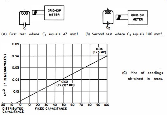
Fig. 27. Measurement of distributed capacitance.
The test can be conveniently made with a grid-dip meter and two, small, fixed capacitors rated for ±1 % tolerance. The equipment is connected as depicted in Fig. 27 A. In this example a 47-mmf capacitor is placed in parallel with the coil for Test 1. The resonant frequency measured with this combination is 7.07 mhz. Therefore, the value for 1/£2 when the 47-mmf capacitor is used is 0.02. When a 100-mmf capacitor is used for C2 , in Test 2 (Fig. 27B), the resonant frequency measured for the combination is 5 mhz ; or, 1/f2 is now 0.04.
Mark off the vertical and horizontal axes of the graph linearly as shown in Fig. 27C. (Values assigned to each division will depend on the range of the two readings which in turn depend on the particular L and C values ). Plot the 1/f2 values against the capacitance values, as shown. Then draw a straight line connecting the two plotted points, and extend the line until it intersects the capacitance axis, as shown. The distributed capacitance of the coil (5 mmf in this example ) is found at the point where the drawn line intersects the capacitance axis.
This test method is algebraically derived from the resonant frequency formula f = ½ pi LC, and the derivation is left as an exercise for the reader who may be mathematically inclined.
CAPACITANCE OF COAXIAL CABLE AND TWIN LEAD
The input cable to a scope, as an example, has a certain capacitance. It also has some inductance and resistance. However, the inductance is comparatively small, and the resistance is very low. Therefore, this is a form of in-circuit capacitance measurement that is easy to make.
Twin lead has less capacitance per unit length than coaxial cable. However, its capacitance is the most prominent parameter at low frequencies. The capacitance of either coaxial cable or twin lead can be measured on an ordinary 60-hz capacitor bridge, with the far end of the cable or lead left open. The measurement can also be made on a 1-khz capacitor bridge for any reasonable length of cable. It is impossible to measure cable capacitance directly on an RF bridge, however, because the distributed inductance then resonates with the distributed capacitance. We say that a section of coax cable acts as a tuned stub when tested at RF. This makes it necessary to use a comparatively low test frequency when measuring cable capacitance.
Measurements of cable capacitance are also used to quickly find the length of a cable. For example, if you measure the capacitance of a 1-foot sample of cable you might read a capacitance of 10 mmf. Then if the capacitance of an unknown length of cable is measured at 1,000 mmf, its length is 100 feet.
TESTS OF HIGH-VOLTAGE FILTER CAPACITORS
High-voltage filter capacitors can be checked for capacitance value with a capacitor bridge or capacitance meter ; leakage tests must be made at rated working voltage to be valid. The flyback power supply of a TV receiver is a suitable source of this test voltage. Select a receiver that provides an accelerating voltage equal to, or slightly greater than, the rated working voltage of the capacitor under test. The voltage can be conveniently measured with a VTVM and high-voltage probe.
Note that the value of the accelerating voltage can be varied within a moderate range by adjustment of the horizontal drive control and the brightness control. To test for leakage, connect the capacitor in series with the high-voltage supply and the high-voltage probe of the VTVM. Any pointer deflection is objectionable and should be regarded as sufficient reason for rejecting the capacitor.
The aquadag coating used on many glass picture tubes is one electrode of a high-voltage capacitor. The other terminal of the capacitor is the receptacle for the high-voltage lead. To measure the capacitance, a pair of clip leads may be used with a capacitor bridge or capacitance meter. Clip one lead to the high-voltage receptacle of the picture tube and the other lead to the aquadag coating ; light pressure will make a satisfactory contact. A typical reading of 900 mmf will be obtained if the coating is in good condition. Scratched-up coatings may give various subnormal readings when tested at different points.
The coating can be repaired in such case by means of aquadag paint.
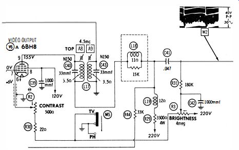
Fig. 28. Waveform W2 normally found on both sides of C41 .
WAVEFORM TESTS OF CAPACITORS
A scope is useful for checking suspected open capacitors.
Consider C41 in Fig. 28. If it is open, little or no image appears on the picture-tube screen. To find out if C41 is open, simply check the waveform on both ends of the capacitor. In case it is open you will find W2 at the input end of the capacitor but absent at the output end. Again, consider the situation in which C41 might have lost a considerable portion of its normal capacitance. In this case you will measure 40 volts peak-to-peak at the input end of the capacitor but substantially less peak-to-peak voltage at the output end. This condition corresponds to low contrast in the picture.
Fig. 29. Bypass capacitor C63 normally holds screen at AC ground.
Always use a low-capacitance probe for waveform tests, unless otherwise specified in the receiver service data. A low capacitance probe minimizes circuit loading. For example, if a direct cable is used to check the waveform in Fig. 28, substantial capacitance is shunted across the comparatively high-impedance circuitry. Consequently, the displayed waveform becomes distorted and reduced in amplitude.
Bypass Capacitors
A bypass capacitor is basically a short circuit for AC. For example, C63 in Fig 2-29 has the purpose of holding the screen grid effectively at AC ground potential. If you check with a scope across C63 you will normally find very little waveform amplitude. But suppose C63 were open ; then a very large waveform amplitude would be displayed on the scope screen. Note that the screen grid is not "dead-shorted" to AC ground by C63, because the reactance of an 0.047-mfd capacitor at 15,750 cycles is about 200 ohms. The screen resistors have a value of about 8K. Hence, a small residual waveform is normally found across C63. The important point is this-in normal operation the screen grid is at AC ground potential, from a practical viewpoint.
Filter Capacitors
Waveform tests are also useful to determine defective filter capacitors (Fig. 30 ). For example, the output ripple voltage from the power supply is normally about 0.5 volt and has the waveform illustrated. Now if C1, C2, or C3 should lose substantial capacitance or develop a high power factor, the waveform amplitude will increase considerably, and its wave shape will change. In this case, bridge each of the filter capacitors in turn with a good electrolytic capacitor while watching the ripple waveform on the scope screen. When the defective capacitor is bridged, the waveform will return to normal.
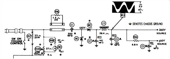
Fig. 30. Waveforms indicate condition of filters.

Fig. 31. C39 and C43 are checked for an open condition with a demodulator
probe and scope.
Signal-Circuit Capacitors
Waveform tests are also useful to localize open capacitors in signal circuits. IF circuitry such as depicted in Fig. 31 is checked with a demodulator probe. Consider a situation in which there is little or no output from the IF amplifier. Then C39 or C43 might be open. To test these coupling capacitors, simply use a demodulator probe and scope to check the progress of the video signal . If you find the video waveform present at the input end of coupling capacitor but absent at the output end, the capacitor is open.
A demodulator probe is also useful to check for open bypass and decoupling capacitors. Practically no video signal will normally be found across C37, C40, or C41 in Fig. 31. However, if one of the capacitors is open, there is substantial video signal across the defective capacitor in a demodulator-probe test since there is no bypassing action present.
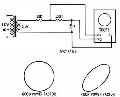
Fig. 32. Oscilloscope test of the power factor of an electrolytic.
OUT-Of-CIRCUIT SCOPE TEST
If you do not have a capacitance bridge available, you can use a scope to test an electrolytic capacitor for power factor, as depicted in Fig. 32. The voltage drop across the 150-ohm resistor is proportional to current and is applied to the vertical input terminals of the scope. The voltage drop across the electrolytic capacitor is applied to the horizontal-input terminals of the scope. Now if the power factor of the capacitor is zero (or very small) you can adjust the gain controls of the scope to obtain a perfect circle on the screen. However, if the power factor is poor, the pattern is an ellipse and cannot be displayed as a circle no matter how the gain controls are adjusted. In case the power factor is extremely poor (equal to 1), you will see a straight, diagonal line on the scope screen. Note that you can calculate the value of the power factor from the scope pattern. Evaluate the pattern as follows:
Center the pattern carefully on the screen. Now note the two points A and B along the vertical axis, as shown in Fig. 33.
Count the number of vertical intervals to A and to B and divide A by B. This will give you a fraction which is related to the power factor. The power factor is calculated as: Power Factor = VI - (A/BF
The power factor thus calculated is the same as the power factor that you would read on a capacitance bridge. Note that for a perfect circle, A and B have the same values in Fig. 33.
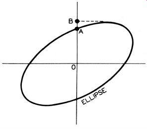
Fig. 33. Phase angle i. given by A and B.
It follows that in this case A/B is equal to 1, and the power factor is equal to zero. Now suppose a straight, diagonal line is displayed on the scope screen. Then A is equal to zero and A/B is equal to zero. Here the power factor is equal to 1.
Accuracy of the measurement depends on use of a good sine waveform in the test of Fig. 32. If the power line has a poor waveform, it is advisable to use an audio oscillator as a source of 60-hz test voltage.