by JULIAN D. HIRSCH
CLASS A, B, C, D ... and G AMPLIFIERS: Most people interested in audio components have by now heard the terms "class A" and "class B" applied to amplifiers. In the last couple of years, the "class-D" amplifier has received some publicity, and more recently we have heard about Hitachi's "class-G" amplifier. These alphabetical classifications describe the electrical operating conditions of an amplifier, whether tube or transistor, and particularly how the signal waveform is handled from beginning to end of a full cycle.
Purely from the standpoint of linearity (inherent absence of waveform distortion), class-A operation is superior to the others. The tube (or transistor) is biased so that current flows in it throughout the entire signal cycle. Figure 1 illustrates this condition, in which the current drawn (at full signal output) varies between somewhere near zero and approximately twice the quiescent or no -signal level (I_o) for the duration of the cycle.
Since the current curve is symmetrical with respect to I_o, the average current passing through the tube or transistor is constant whether or not there is a signal present.
Under no-signal or very-low -signal conditions (which is the way high-fidelity amplifiers operate much of the time), the efficiency of a class-A amplifier is essentially zero, meaning that there is a constant power-supply input with little or no signal output (this is analogous to the miles per gallon achieved by a car standing with its motor idling). But even at full power, the class-A amplifier is less than 33 percent efficient. This is no problem in preamplifier or other low-level stages which consume little power, but it re quires huge power supplies and heat sinks for the output stages of a powerful solid-state amplifier.
In class-B operation, the output device conducts for at least half of each full cycle. This is shown in Figure 2, in which the quiescent current 10 is quite small compared with the maximum drawn at the positive signal peak. When the signal waveform goes slightly negative, the output transistor is cut off so that it draws little or no current, and the output waveform is clipped accordingly. This is obviously a severely distorted condition, but if a second transistor is operated during the negative half-cycle of the signal waveform and the two outputs are combined, the resulting waveform is a reasonable replica of the input signal. (This mode of operation, called "push pull," is used in virtually every audio power amplifier designed for home music systems, whatever its class.) Since the power-supply current (10) through the output transistors under no-signal conditions is much less than in class-A operation, a class-B amplifier runs relatively cool when not driven very hard. And, at full power, it is about twice as efficient as a class-A amplifier. The result is high power capability without the cost, size, weight, and current -consumption penalties exacted by class-A operation. Many amplifiers are operated with their biasing set between the class-A and class-B conditions, and these class-AB (or simply class -B) circuits are by far the most used in high-fidelity amplifiers.
Insofar as its output devices are linear and perfectly matched in their characteristics, the distortion of a class -B amplifier stage need not be any greater than that of a class-A amplifier. Such perfection does not exist in real life, of course, and there is always therefore some mismatch between the two halves of the waveform at low values of the signal waveform, where the transition from one side to the other of the push-pull pair takes place.
This can be minimized by biasing the stage toward class-A operation, but such biasing reduces both output and efficiency.. The inevitable mismatch gives rise to the effect known as "crossover distortion," which appears as a notch or jog in the waveform near where it crosses the zero -voltage axis. These small discontinuities are widely believed to be most responsible for the kind of distortion heard in transistor equipment. That point remains debatable, but we can all agree that any distortion is undesirable.
A third operating condition, known as class C, is widely (and mostly) used in radio-frequency transmitters and there fore need not concern us unduly here.
Briefly, a class-C stage conducts for less than half the signal cycle. In audio terms, this represents almost total distortion, but in a transmitter the class -C stage serves its purpose very well.
The current Federal Trade Commission regulations on the rating of amplifier power have made the industry painfully aware that the one-third full-power pre conditioning level is uncomfortably close to the. 40 percent area where class-B amplifiers are least efficient. In order for many amplifiers to meet the 1-hour, one-third-power requirement, it has been necessary to grossly overdesign their cooling systems; this has meant very large heat sinks and (in some high-power units) fans. Clearly, a more efficient amplifier would be a boon to both manufacturer and consumer, for it would make possible a smaller, lighter, cooler, and (one hopes) cheaper product.
One such approach is generally referred to as "class D," and it has been proposed for some years. Although various manufacturers are reported to be working on such systems, Infinity is the only company to date that has advertised a high-fidelity product working in this manner. Class-D amplification is a pulsed system that takes advantage of the fact that the heat dissipation in a transistor is lowest when it is either fully on or fully off (in a normal amplifier, it is usually between those states). The signal handled by the class-D amplifier is a continuous stream of narrow pulses occur ring at a frequency far above the audible range (typically several hundred kilohertz). Switching transistors are used in stead of the conventional linear types generally found in audio amplifiers.
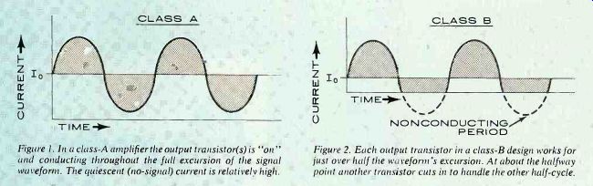
Figure 1. In a class-A amplifier the output transistor(s) is "on" and
conducting throughout the full excursion of the signal waveform. The quiescent
(no-signal) current is relatively high.
Figure 2. Each output transistor in a class-B design works for just over half the waveform's excursion. At about the halfway point (Another transistor cuts in to handle the other half-cycle.
The pulses serve as a carrier for the audio modulation, which can be applied in any of several ways. Pulse -width modulation is probably the easiest to understand. The audio waveform is used to vary the width of the pulses passing through the amplifier. For example, as the waveform goes increasingly positive, it can be used to widen the pulses; the negative portion of the audio signal can be used to make the pulses narrower.
The actual power dissipated within the amplifier is constant during this process.
To restore the audio signal at a high power level before it goes to the speakers, only a low-pass filter in the amplifier output is necessary. Such a filter will pass the slow variations in average output ("slow" meaning at an audio rate) while excluding the ultrasonic pulses from the speakers. To the extent that the modulation can be performed linearly (and it can be made very linear), the distortion of the amplifier can be made al most as low as desired.
The advantages of the class-D system are obvious. For a given audio power output a class -D amplifier can be much smaller, lighter, and cooler than a conventional design. On the negative side, the presence of very powerful high-frequency pulses makes it necessary to con trol the radiation of harmonics that could interfere with radio and TV reception.
No doubt there are other technical difficulties to be overcome as well, and these have contributed to preventing a whole sale adoption of the class-D approach.
The very newest "class" in amplifier operation is a development by Hitachi.
They originally called it "class E" but have now shifted the nomenclature to "class G." The class-G amplifier uses, in effect, a low-power and a high -power output stage operating together in such a way that each works with relatively high efficiency. At low signal levels the low -power stage drives the speakers; the transition to the more powerful output transistors (which operate from a separate, higher-voltage power supply) takes place smoothly at the point where it be comes advantageous to do so. The result is an amplifier with a much higher overall efficiency than a conventional class-B device, and this brings immediate dividends to the consumer in reduced weight, size, and power consumption.
Through appropriate design, the one third-power operating point can be placed in the most efficient portion of the amplifier's operating range, thus obviating the need for the over-designed heat sinks required to meet the FTC rules with a conventional amplifier. The operating area where the signals from the two stages combine is a potential source of distortion (it is similar to crossover distortion, though it does not tend to occur at the zero -voltage axis), but Hitachi was able, by means of an inexpensive circuit modification, to eliminate this almost entirely. The result is an amplifier whose distortion is at least as low as that of any comparable conventional amplifier.
This approach is not entirely new, since something similar was attempted in the ill-fated Mattes amplifier back around 1965. It used the low -power driver stages to feed the speakers at low levels and transferred the output to the more powerful class -B outputs as the signal increased. In a sense, it was an idea that was ahead of its technological time, for the low reliability of the semiconductors available at that time proved to be its undoing.
Superficially, the new Quad 405 "current dumping" amplifier would seem to be based on a similar concept, though with a bit of a difference. In essence, it employs a highly linear class -A amplifier to supply the voltage (and presumably the current associated with low -power outputs) to the speakers. A more powerful class -B amplifier is used to supply the heavy currents needed at high power levels. The aim was to effectively eliminate crossover distortion in a fairly powerful amplifier (about 100 watts per channel) without going to class-A operation. We have not seen the Quad amplifier, but judging from what we have read about it, it does its job effectively and it is a very lightweight unit as well (it weighs about 20 pounds).
A relatively new approach to the "class" question in amplifier operation is being employed by a few manufacturers. Special monitoring circuits automatically adjust the bias applied to the output stage in accordance with the power-output demands of the audio signal. The amplifier is therefore operating, from moment to moment, closest to the class that, in the view of the designer, produces the desired results. In general, the amplifier's operating characteristics are shifted to approach class A or class B, depending upon the signal.
IF you feel that the question of "which class is best" is left unanswered, you are quite correct. Some amplifiers may in truth have audible advantages, but we have never encountered an amplifier whose superior characteristics--when there were any-were clearly linked to a specific mode of operation. There are many ways to design an amplifier, and I'm sure that the advocates of each technique can provide specific reasons for their particular approach. Perhaps it need not be repeated, but in all areas of high fidelity audiophiles should keep their eyes and ears fixed on results achieved rather than on the techniques used to achieve them.
Also see:
PHONO CARTRIDGES: A short course in cartridge types and specs for the buyer
CLASSICAL DISCS and TAPES; Lazar Berman's "Appassionata" by ERIC SALZMAN; The Symphonies of Sweden's Hugo Alfven, by DAVID HALL
Source: Stereo Review (USA magazine)