MAKING CONNECTIONS---Proper hook-up is vital to getting the best from your system / by Dawn Gordon.
BY DAWN GORDON
PROPER HOOK-UP IS VITAL TO GETTING THE BEST FROM YOUR STEREO AND VIDEO COMPONENT SYSTEMS.
FIGURING out the best way to connect the components of a stereo system is as critical as deciding just which units to buy. After spending months carefully selecting components, many an unfortunate novice audiophile has found himself sprawled on the living-room floor surrounded by empty boxes and poring over wiring dia grams trying to decide whether to connect a time-delay system ahead of a tape deck in the signal path (after is usually better) or whether it's okay to connect the audio output of a video-cassette recorder to the auxiliary input of a receiver (it is).
But connecting hi-fi and video components is relatively easy once you get the hang of it and learn to use the various connectors and adaptors that are available. And making the right connections will enable you to get the most out of your system.
CONNECTING SPEAKERS
Most of the source and signal-processing components in a system come complete with cables for connecting them to an amplifier or receiver. With speakers, however, you generally have to buy the cable separately. You don't need super-thick cable, but avoid the 24-gauge zip
cord that is sometimes sold as "speaker wire." STEREO REVIEW recommends using at least 18-gauge zip cord or 16-gauge heavy-duty zip cord. For long runs, use the heavier gauge. But if you think you need a thicker, "exotic" speaker cable, go ahead-it certainly can't hurt.
Beginners are sometimes con fused by instructions to connect their speakers "in phase." It's actually very simple. A speaker is connected in phase if the positive (usually red) terminal on the amplifier is connected to the positive (red) terminal on the speaker and the negative (usually black) terminal on the amp to the negative (black) terminal on the speaker.
Even with a very long cable run, you can keep the connections straight by using the coding incorporated in the cable itself: either the two conductors will be differently colored or else one of them will have a ridge or a groove in the plastic insulation around the wire.
Additional speaker pairs are connected in the same way, but if you plan on playing more than one pair at the same time, you need to be, careful or you could blow out your amplifier. Check your amplifier's specifications to see what impedance it can handle, and then be sure ' that the combined load presented by your two (or more) pairs of 6, speakers stays above that. To figure out what the combined load is, follow this formula:
[R1 x R2] / [R1 + R2]
where R, is the nominal (rated) impedance of one pair of speakers and R2 is the impedance of the other pair. If you have, say, a pair of 8-ohm speakers in your living room and a 4-ohm pair in your bedroom, playing them together will present a combined impedance of only 2.6 ohms. A lot of amplifiers will balk at that, particularly since the impedance may fall even lower at certain frequencies.
Another approach is to buy an accessory speaker-switching unit. De vices are available that can handle from two to six pairs of speakers in any combination, ranging in price from $5.95 (Radio Shack) to $280 (Russound SD-4) for one with multiple independent volume controls.
Most cost around $80, and some include a protection circuit or an impedance-matching transformer so you can't blow an amp.
CONNECTING SOURCES
Stereo components sold in the U.S. typically use "RCA-type" phono plugs, generally connected with short lengths of shielded cable, for source inputs and outputs. Instead of positive and negative terminals as speakers have, each input and output consists of a pair of terminals for the two channels; the plugs at each end of the cable are differently colored so you can match them up correctly ("red for right" is an easy memory device since red is usually one of the two colors).
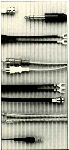
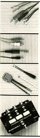
--- Top photo shows three ways to terminate a speaker cable: bare wire, banana plugs, spade lugs. Next are three ways to plug one component into another: top to bottom. RCA-type phono plugs, stereo phone plug, and mini stereo phone plug. Third photo shows video connectors: clockwise from top, 75-to-300-ohm matching transformer, F connector at end of coaxial cable, signal splitter. Bottom photo shows a video switcher. All of these parts are from Radio Shack.
Inputs for a record player, tuner, or tape deck are normally identified as such on the back of a preamplifier or receiver. If there is no specific input designated for a digital or video source (a Compact Disc player, video tuner, PCM digital tape recorder, VCR audio output, etc.), the "auxiliary" input can be used. Never try to use the "phono" input for one of these "high-level" sources.
High-level sources can also be connected using a tape input if you're not using it for a tape deck.
The tape input is especially flexible because, unlike the other inputs, it is paired with an output. Since most people will want to record on a tape deck as well as using it to play back recorded tapes, there have to be …
IF THE PREAMPLIFIER OR RECEIVER HAS NO SPECIFIC INPUT DESIGNATED FOR A DIGITAL OR VIDEO SOURCE, USE THE AUXILIARY OR TAPE INPUT. NEVER TRY TO USE THE PHONO INPUT FOR ONE OF THESE HIGH-LEVEL SOURCES.
…connections enabling signals to travel both ways, from the preamplifier to the tape deck and from the tape deck to the preamp. This input output circuit is called a tape loop (or tape-monitor loop). Preamplifiers and receivers vary in the elaboration and flexibility of their tape circuits, but these days most of them that can handle two or more decks have built-in dubbing connections so that one deck can function as the program source for the other.
In the overall signal path from a program source to the loudspeakers, the tape loop comes before the preamplifier's volume and tone controls. Thus, the signal to the tape heads is not affected by these controls. This makes it possible to use a tape loop to connect various signal processing components such as an equalizer, a noise-reduction system, or a dynamic expander. Ordinarily, these components are connected into the preamplifier's tape input output terminals, and then the tape deck, if any is used, is connected into similar terminals on the signal processor. The tape-monitor switch on the preamplifier permits use of the signal processor whether or not the tape deck is being used.
If you have a separate preamplifier and power amplifier, or if you have an integrated amplifier with a set of pre-out/main-in jacks, you can avoid tying up a tape loop by connecting a signal processor be tween the preamp and power-amp sections. This is particularly desirable if you have a time-delay or ambience-synthesis system with a separate power amplifier for the rear speakers. If it's connected through a tape loop, you'll have to adjust the volume for the rear speakers separately every time you change the main volume setting. If it's connect ed between your preamplifier and the power amplifiers, you can set the optimum volume balance initially and then adjust the volume with the control on the preamp.
For some elaborate systems with many source components, even a high-quality preamplifier may not provide enough inputs. A program route selector may be the answer.
Such a device connects like a signal processor and can switch various in puts and outputs through your sys tem, from extra CD players to multiple tape decks with cross-dubbing facilities. Prices depend on the features offered and range from $25 for a basic Radio Shack unit to $230 for the versatile dbx Model 400.
POWER CORDS
Most components use some power, and if you have an elaborate system you might wonder what to do with all the power cords. Fortunately, only the power amplifier (or power-amplifier section of a receiver or integrated amp) is likely to draw a significant amount of power. It is perfectly safe, therefore, to use multiple-socket plugs to connect several components to the same wall outlet or to the same a.c. outlet on the rear of an amplifier or receiver. If your amplifier has both switched and un switched outlets, use the switched outlet for components you want on only when the amplifier is on, the other(s) for those you don't mind having on all the time.
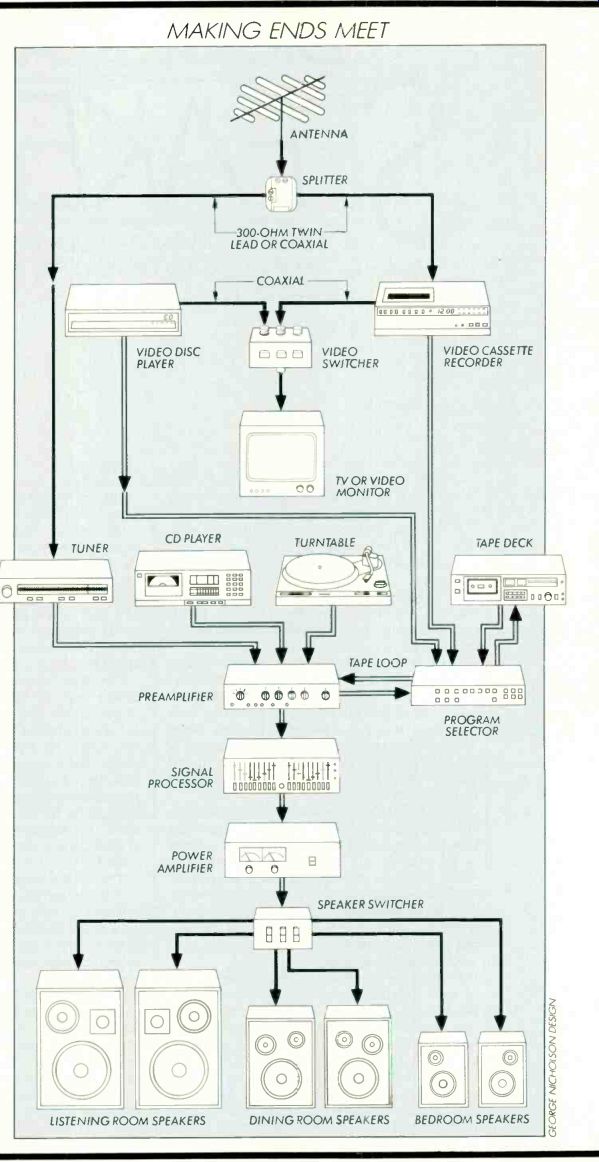
--61 MAKING ENDS MEET
CONNECTING ANTENNAS After you install a super multi-element TV/FM antenna with rotor on your roof for the entire neighborhood to marvel at and then route the cable down to your living room, you may be in for a surprise. Most coaxial TV and FM antenna cables are terminated in an F-style connector. This type of 75-ohm plug is found on most video cables, and to day's FM tuners have the appropriate inputs for it. But if you hap pen to have a tuner from a few years back, there may be no 75-ohm in put, just the more familiar 300-ohm twin-lead terminals.
What you need in this situation is a 75-to-300-ohm matching trans former, available at any local Radio Shack for about $3. Only slightly bigger than a standard headphone plug, the transformer simply screws or pushes onto the F-connector at the end of the antenna cable, and its other end is connected to the standard 300-ohm terminals the same way a twin-lead or dipole antenna is. (In the event that you have the opposite mismatch, you can reverse it to use as a 300-to-75-ohm trans former instead.)
VIDEO TO AUDIO
If you're using a combination TV/ FM antenna, you'll have to separate the different signals coming down the cable and feed one set to your TV and the other to your FM tuner.
For this you need a video splitter to divide the signal into two outputs.
One goes to your FM tuner, the other to the 75-ohm antenna input on your TV set or video tuner.
Video equipment often uses RCA-type phono plugs as well, and you'll need cables equipped with these if you want to get the best possible performance from a high-quality component video system. The r.f. modulation in conventional TV sets and video tuners can degrade the program quality from non-broadcast video sources such as video discs and tapes. The picture will look better if you bypass the tuner circuitry and feed the signal directly into the video circuitry.
This sort of direct or composite video connection usually requires RCA-plug cables or F-connector-type coaxial cables. Simply connect a set of cables between the video outputs of the disc or tape player and the video inputs of a component TV monitor (conventional TV sets don't have the right inputs).
Use another pair to connect the player's audio outputs to an auxiliary or tape input in your stereo sys tem. Place your speakers on either side of the TV screen (but not too close if the speaker system or the TV set isn't magnetically shielded), and get ready to enjoy audio/video performance far beyond anything you've heard or seen from broad cast TV.
MAKING ENDS MEET :
Routine maintenance of system connections is a good idea. Every year or so, unplug everything, wipe all the plugs with paper towels, and reinsert them tightly, twisting the phono connectors as you do so.
This will ensure good, firm contacts.
When you're putting your system together in the first place, plan everything out beforehand, know where everything goes, and be aware of the different types of connectors that each component needs.
You should have little trouble making the right connections.
----------------
Also see:
DIGITAL-READY SPEAKERS --- How much power can your speakers handle? Can they stand up to the peaks put out by Compact Discs?