AMAZON multi-meters discounts AMAZON oscilloscope discounts
In the previous section we found that in the G.E. system the eye was a special camera which used a special matrix of light sensitive cells. In the system we are about to investigate, we find that a standard vidicon camera tube or an optional silicon-diode type tube is used. The system digitizes the video output of the camera so the information can be used by a microcomputer and its associated control system.
THE SPATIAL DATA SYSTEMS EYECOM II
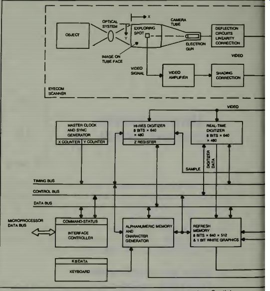
Fig. 1. A Block diagram of the Eyecom robotic-eye system (courtesy Spatial
Data Systems, Inc.).
This is a picture digitizer and display system. Its general operation and assembly are shown in Fig. 1. Notice in the diagram that the reflected light from the object goes through an optical system and impinges directly on the face of the vidicon camera tube. There, a beam of very small diameter scans the face of the tube and generates the video signal, which is analog in nature. The output goes to a display picture tube for a person's inspection and also goes to a digitizer and from there the information goes, via control, data, and timing buses, to the computer section. Most of the electronics are used-to enhance, expand, or update the picture as seen on the monitor. The joystick can place a marker on the video monitor screen, and move it as desired. I call your attention to a block near the camera tube, the shading correction block. The circuits contained in this block provide the color enhancement and correction which can be accomplished in the EyeCom System. The system uses a scanning system which is compatible with standard television.
A light image of the object is produced on the photosensitive face of the camera tube by an optical system containing an ordinary camera lens. The system uses a standard C mounting which accepts television lenses, however, a universal screw type mounting for 35 mm camera lenses can be provided. In normal operation the image is stationary and the brightness at any point of the image is a function of the X and Y coordinate position on the tube face. The image brightness at each point is then defined as a third dimension or Z coordinate. This is converted into the video signal by repeatedly scanning the image with an exploring spot formed by the electron beam of the camera gun. Notice the Eye comcamera in Fig. 2. It may look familiar to you. It is relatively small and easy to mount in a number of either fixed or moving base positions.
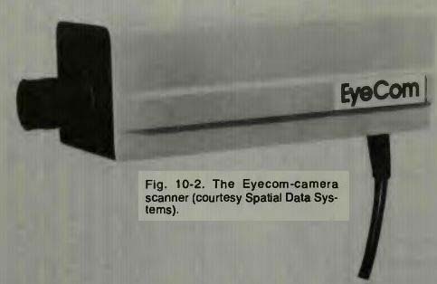
Fig. 2
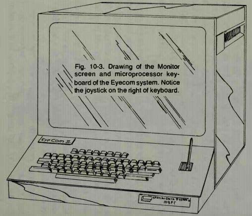
Fig. 3
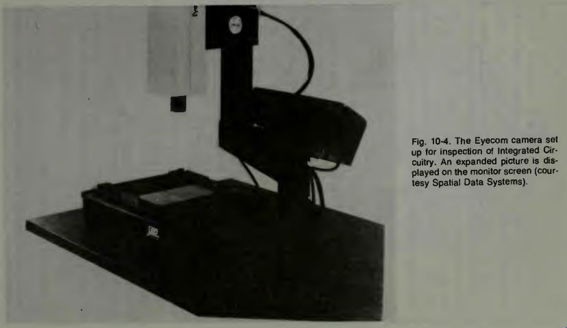
Fig. 4
THE INTERFACE CONTROLLER
All of the EyeCom functions are controlled through the control bus. This bidirectional bus transmits control signals to the displays, digitizers, and registers from the interface controller. It also sends status signals from the EyeCom internal units to the interface controller. Data is transmitted throughout the system on the data bus. The interface controller connects the microprocessor bus to the EyeCom bus. The keyboard used with the microprocessor connects independently to the interface controller. Figure 3 depicts the monitor screen unit and the microprocessor keyboard unit.
USING THE EYECOM SYSTEM IN AN INSPECT-REJECT-ACCEPTANCE MODE
With proper lenses this system can inspect with tolerances as fine as 0.0001 inch! Using a Macro lens this unit is said to be able to check hole dimensions and locations in machined parts to a resolution of 0.0005 inch. The use of the EyeCom in this application is called the automated parts measurement application. Ultra small integrated circuits can be checked for accuracy, completeness, and tolerances in the PMS mode. One physical set-up for such inspections is shown in Fig. 4.
The smallest of circuits can be inspected for missing connections, for short circuits, for cracks in the base structure and so on. Since the data can be fed into the microprocessor, its computer can make a line by line comparison with referenced information gained from a perfect unit previously examined and stored.
In some visual inspection systems the table top upon which the part is mounted is caused to move by servo control commanded by the computer. The table top-and thus the part-can be moved.
The main requirement is good contrast between the table or mounting base and the part, and between the part mass and the hole. An automated operation is illustrated in Fig. 5.
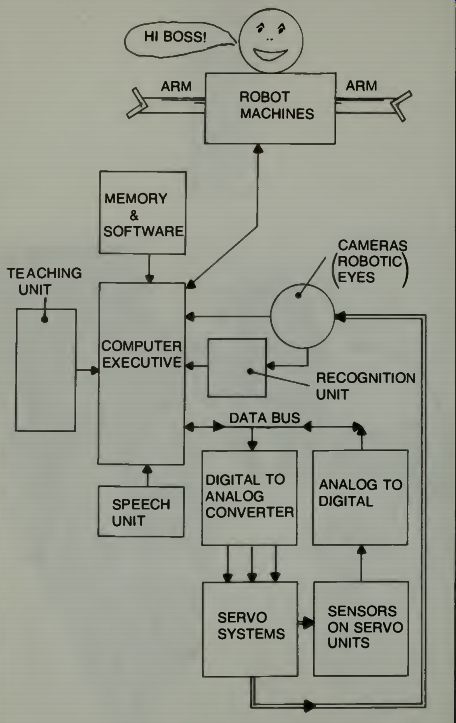
Fig. 5. A general concept of a robotic control system using microcomputers
and robotic eye.
THE EYECOM DIGITIZER FLOW OPERATION
The X-register and the Y-register are loaded from the data bus with the location of the pixel to be sampled and digitized. The X and Y registers are continuously compared with the spot position as provided by the sync generator counters on the timing bus. When the scanning spot reaches the stored X, Y address the address comparator issued a sample pulse to the high resolution digitizer. The command to sample and digitize a pixel is received by the digitizer control from the interface controller through the control bus. The sampled video is digitized into an 8-bit binary Z-value and then stored in the Z-register where it can be accessed through the controller by the computer.
The physical electronics of the system are shown in Fig. 7. Notice that the circuit cards are so arranged that they are easily removed for inspection, replacement, or whatever.
Finally we examine a block diagram of the EyeCom color digitizer system in Fig. 8. If one wants to make a color display of something which isn't colored then the data from the picture display is converted to color by the optional color look-up table. Each of the 64 gray levels in the most significant 6 bits of the picture display memory is assigned a color.
Colors are stored in the table by the digital computer. Colors are defined as proportions of the primary red, green, and blue values using 8-bits per primary. As pixel values are read from the refresh memory, they address the color look-up table.
Color values are then converted to video signals.
In the block diagram we find four solid state random access memories in the refresh memory section. One of these is used for display of graphics and the other three are used for color pictures. Color pictures are produced by superimposing three separations in red, green, and blue on the color display picture tube. Each separation contains tonal variations rep resented by an array of pixels stored in the red, green, and blue refresh memories.
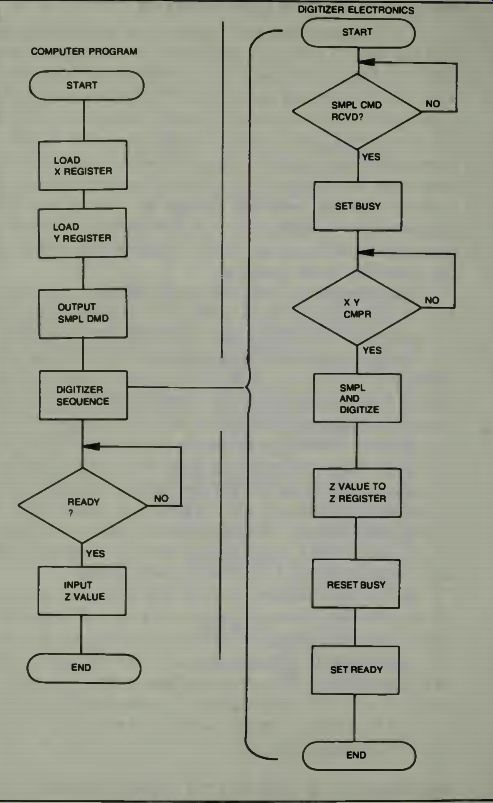
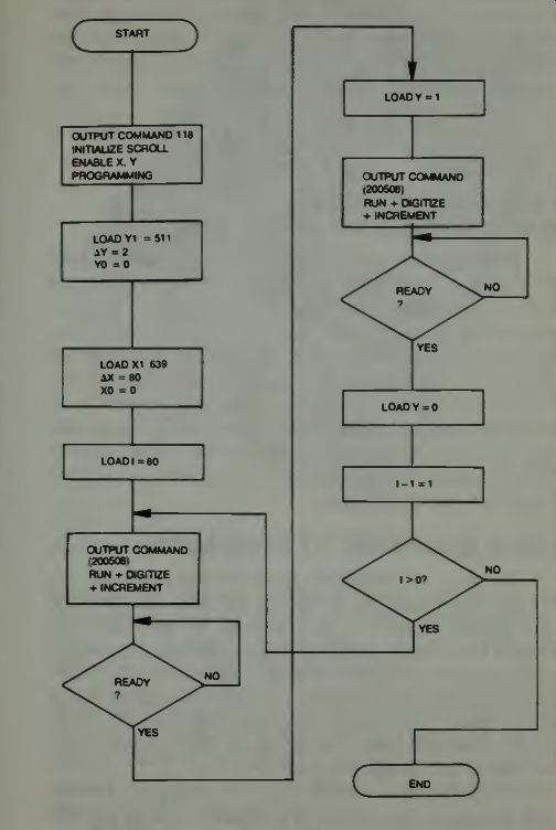
Fig. 6. Computer programming and digitizer flow diagram (courtesy Spatial
Data Systems).
INVESTIGATIONS OF ROBOTIC EYES ATTACHED TO GRIPPERS
The idea of mounting a camera on the wrist of a gripper so it can see what the gripper is trying to grasp obtained results which indicate that this may be something which we can use to advantage if it is refined and improved. The future of this kind of system titillates the imagination. Smaller cameras, better lighting methods, ruggedization of the equipment, and good accurate algorithms might well bring about a whole new world of usefulness for the robotic arm and robotic eye systems.
More on this research is in the 1979 winter issue of Robotics Today.
A NOTE ON ONE INDUSTRIAL DEVELOPMENT TREND USING ROBOTIC VISION
In Japan, where there is great effort being made toward development of the automated factory, the development of the two-handed robot using three dimensional vision has been progressing for some years. The use of such robots able to coordinate the use of two hands and multiple fingers in the assembly of batch products is under intense study. At the University of Waseda, Tokyo, a robotic machine has been built which has two hands, two legs and two video camera eyes. This robot can recognize some speech and can speak to a limited extent. The use of two video cameras give a three dimensional view of objects.
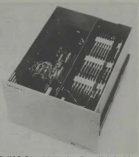
Fig. 7. The Eyecom electronics package with removable circuit cards (courtesy
Spatial Data Systems).
IS THERE AN ADVANTAGE TO A TALKING ROBOT?
We know it is technically feasible for an electronic circuit to recognize and accept human speech and to generate some kind of response to those sounds. We also know it is possible for an electronic circuit to generate human speech so that it conveys intelligent messages back to us. These circuits are available at the present from Telesensors, Radio Shack, Texas Instruments, and other suppliers. We have already discussed talking units, so we will focus on voice recognition and human acceptance.
Obviously, for a central computer doing batch work voice communication with each terminal or user is not efficient. A high-level language is better. This is also true of industrial applications where more than one robot is used and the actions of all concerned need to be coordinated. However, individual and domestic robots might become much more efficient with voice recognition. The goal is to give the user the maximum support rather than to try to optimize the utilization of the computational resources.
English is not an exact language. Some people say "cut off the light," some say "kill the light," and some say "turn off the light." If we assign special words for each task, we are actually inventing a high-level language, and have gained nothing by adding voice recognition. In an effort to compromise Ruly English was developed.
Ruly English uses regular English syntax but limits each word to one meaning. It is not a colorful language, but is precise, and immediately understandable. One might say it is a subset of the English language. It is possible to pictorialize these ideas in an illustration. See Fig. 9.
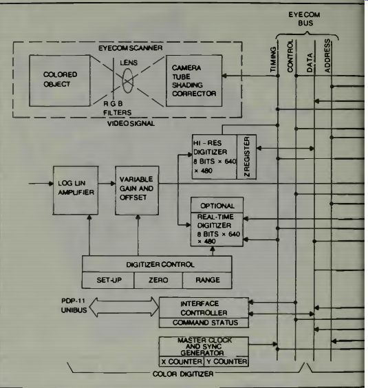
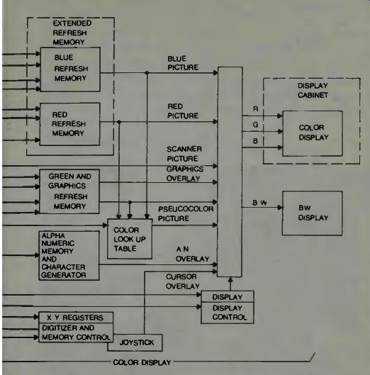
Fig. 8. The Eyecom block diagram of the color system (courtesy Spatial
Data Systems).
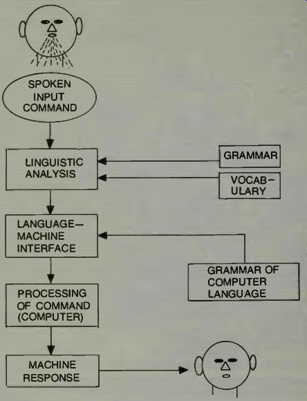
Fig. 9. A block diagram of a natural language man-machine communications
system.
SOME GENERAL RULES FOR VERBALLY COMMUNICATING WITH ROBOTS
Sanyo Electric has demonstrated a television receiver that responds to voice commands to turn itself OFF and ON and to switch stations. The receiver intelligence unit does this by comparing the voice input from selected persons to voice patterns which have been stored in its memory. At the time of its demonstration this unit had a 30 word capability in vocabulary and could distinguish the voices of two different people. An expansion on this concept would permit people to play computer games using vocal responses, according to the research information which is available. However, this unit has problems identifying a "learned" voice when it has a cold.
This could create problems in the workplace.
There are other problems. Many humans wouldn't mind working next to a machine they can't program, but few will work next to one they can't stop in an emergency. So the robot would have to accept only certain voices for programming, but any voice for operation. Of course, by the time these robots are common in factories, today's children will be the workers (maybe) and growing up with talking TVs and learning aids may cause them to accept all this much easier.
The popular adventure games are an example of trying to get a computer to understand English. The earliest ones used two word commands. This was not a noun and verb as you might expect. Since these were commands, the noun was the implied "you." To command was a verb and either a verb modifier (GO NORTH) or a direct object (THROW KNIFE). If the action implied an indirect object, as in this example, the computer asked "TO OR AT WHAT?" The computer looks to see that it "knows" the verb and object. If not, it tells you it doesn't understand. Next it checks to see the verb is applicable to the object. If not, it tells you so! (CAN'T EAT HOUSE!) Finally it checks to see if you have the object. You can't throw a knife you don't have! Since the first simple programs, routines have been developed allowing the computer to pick the important two words, plus indirect object, from a complete English sentence.
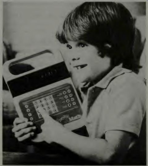
Fig. 10. Texas Instruments Speak and Math machine (courtesy Texas Instruments).
There are four primary significant models of language and these are; the fixed sentence model, the finite states model, the syntactical model, and the transformational model.
These are described in detail in Syntactic Structures by Chomsky, (Monton & Co, the Hague, Paris, 1957). The first two are the most applicable to present voice recognition technology.
In the fixed sentence model there is simply a list of all the allowed sentences. One defines each sentence with a mathematical term. If we develop a whole list of sentences which are unique then when the computer receives an order it essentially compares that order to that series of sentences and chooses one which matches or most nearly matches the command.
The finite states model is essentially what the adventures use.
SOME CONSIDERATIONS OF AUTOMATIC SPEECH RECOGNITION BY MACHINES
Once the meaning of a sentence has been decoded, there is still the problem of identifying the speaker.
There are two general ideas for recognition of human speech. These are a system where the pitch and spectral characteristics can be analyzed and related to some person, and a system where the electronic circuitry can extract phonemes and from a tabulation of these phonemes identify the different persons speaking.
In a study at the Rome Air Development Center, Griffiss Air Force Base, New York, an analysis of human speech was conducted. It was found that speech sounds are primarily of two types-voiced and unvoiced. For voiced sounds such as the vowels the vocal chords vibrate and produce a line spectrum which has a fundamental frequency in the 70-180 Hz region for males, with harmonics extending to 8,000 Hz and even higher. The unvoiced sounds are produced by the turbulence of the air stream as it exits the mouth and not from the vocal chords at all! There are also sounds such as Z which require both techniques.
There are about 40 basic phonemes in the English language. There have been detailed studies to find out just what identification characteristics there are in human speech, so we can make machines do what we do, recognize who is speaking.
A block diagram which shows a system for recognition of human speech, based on pitch and spectral characteristics is shown in Fig. 11. In a typical operation using this type system for speech recognition, the speech is fed into the spectrum analyzer and the pitch extractor as shown. The output of these units is sampled every 20 milliseconds, digitized, and sent to the computer. The computer knows what characteristics it is looking for because it has previously stored patterns of speech.
The system shown in Fig. 11 uses some clues to identify whom is speaking, or has spoken. One set of clues is to use the speakers fundamental frequency-the average pitch and the maximum and minimum of his speech tonal range. A second set of clues may be extracted from the speech spectrum, the measured value of the highest peaks of sound, the ratio of the amplitude of the sound, to the valley amplitude following the highest peak and the measurement of the peak amplitudes, and where they occur in the spectrum. One manner in which the information may be used is to form multi dimensional histograms. Then during the recognition process the summed-squared-deviation between what is in the computer memory and the sound now coming in through the system can be compared. If the sound being evaluated has the same or close to the minimum summed-squared-deviation of the memorized pattern, then the computer decides that this is the speaker whose histograms are being used as a reference.
Refer to Fig. 12.
Examine a block diagram of the method of speech identification that uses the automatic phoneme recognition concept. This can be illustrated as shown in Fig. 13. This block diagram is the one which would use the algorithm illustrated in Fig. 12. Basically, this equipment would make use of analog threshold-logic operating on the rectified output of the filter banks to provide such features as spectral energy, spectrum slopes, local maxima-minima, transitions, sequences, and simultaneous occurrences. AH of these features are used in speech recognition systems.
In the RCA equipment which is illustrated in the block diagram, Fig. 13, the input is conversational speech and the equipment is used to recognize, and segment from the speech, a set of phoneme-like elements. During the occurrence of each such element the slope of the logarithmic spectrum was employed to measure the speaker's characteristics-of-speech by integrating the spectrum slopes of the analog signals, which are derived from the filters, and then quantizing these to three levels; positive, negative, and zero.
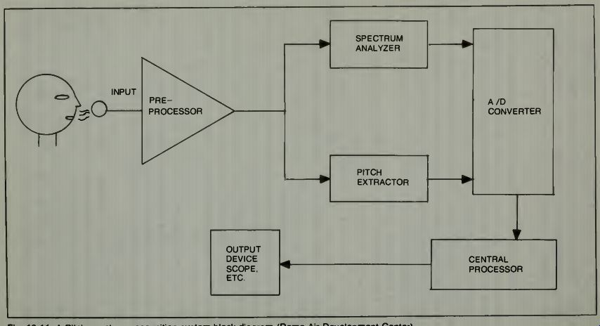
Fig. 11. A Pitch-spectrum recognition system block diagram ( Rome Air-Development
Center).
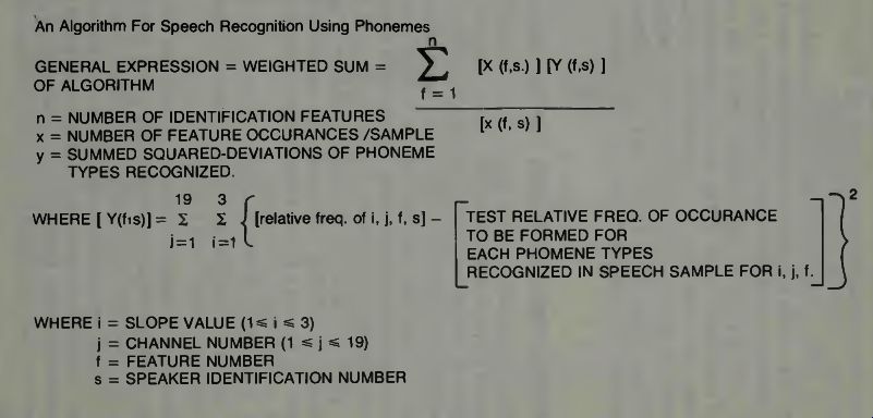
Fig. 12
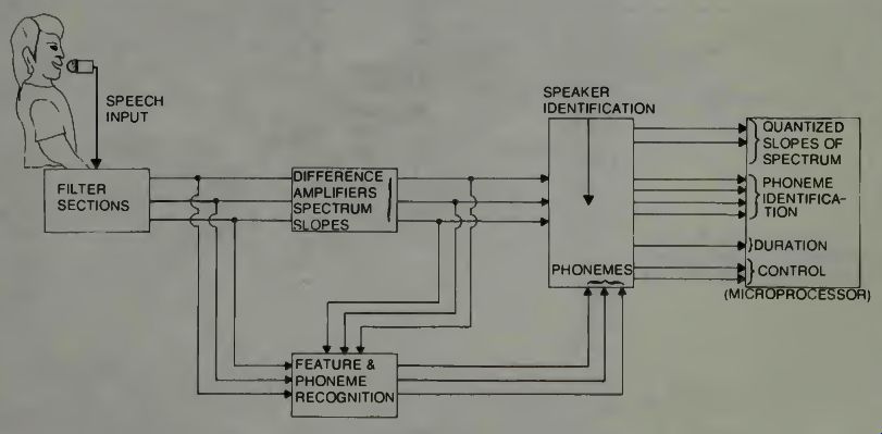
Fig. 13. A possible robotic voice tract, configuration. This actually is
from Ti's Speak and Spell device (courtesy TI).
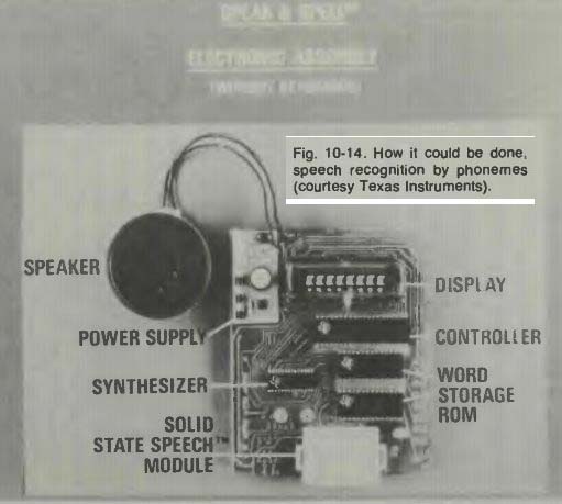
Fig. 14
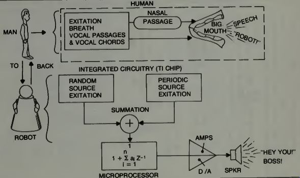
Fig. 15
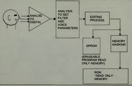
Fig. 16. TI's speech analysis and coding process to get proper
speech formants into memories (courtesy TI).
TEXAS INSTRUMENTS DEVELOPMENTS IN SPEECH CIRCUITRY
Texas Instruments has done much advanced research in both speech synthesizing, speech recognition. They hold a patent for a single stage digital speech-synthesis filter. We have indicated how important filters are in breaking down the components of speech so that they may be analyzed. In fact, the unit shown earlier represented a major price break in voice synthesis using a breakthrough called linear predictive coding, which we discussed in an earlier section. Figure 14 shows the circuitry. Since using the inverse of this technique may provide a similar breakthrough in speech recognition, we will take a closer look.
We have indicated the algorithm solving unit in the microprocessor block of Fig. 15. It represents the summation of a series of terms from i = 1 to i = n.
"Brute force storage of speech signals can be accomplished by sampling and converting speech at an 8 to 10 kHz clock rate. This results in a digital data rate of 100,000 bits per second of speech. Pulse-coded modulation codecs and companding techniques have found acceptance in all new, all digital, telecommunications systems, but their data rate of 64,000 bit per second is still high.
"Linear Predictive Coding produces speech quality nearly comparable to either of these techniques, yet it only requires about 1,200 bits per second. With the advent of 128K bit and larger storage devices, LPC packs minutes of high quality speech into memories that could hold only one or two seconds of speech using other techniques." The secret is that LPC predicts the parameters of the next speech sample from a linear combination of the values of the preceding speech samples. This is possible because of redundant information in speech signals caused by a limited number of the formants in the human speech production system. LPC essentially eliminates unnecessary information in human speech and keeps only the data required to drive the synthetic model.
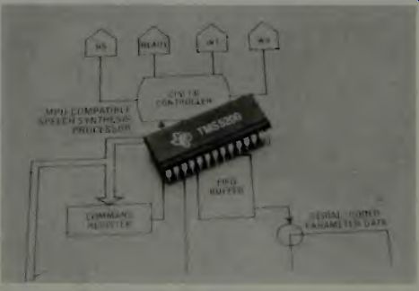
Fig. 17. The TMS5200 speech chip from Texas Instruments. FIFO stands for
first-in-first-out and relates to signals into the buffer.
Speech sounds are recorded and digitized using special recording facilities that virtually eliminate background noise and preserve a high signal-to-noise ratio for the digitizer.
Then the sophisticated signal algorithms of the type we have examined previously, are used to extract pitch and energy and slope information from the recorded data. Using a minimum-mean-square predicted-error criterion, the computer program computes an optimal set of coefficients for the vocal tract filter of the model electronics unit. The response of this filter, then, when suitably excited, will closely resemble the original speech model .
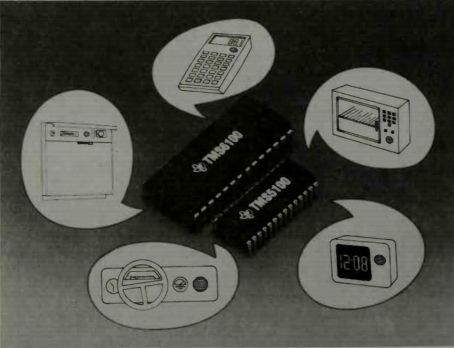
Fig. 18. Some possible
uses, in addition to robotics, for the TI speech chips (courtesy TI).
In the next stage of the LPC system a frame repeat analysis takes place. Here, similar sets of reflection coefficients (40 bits each) are eliminated from the data stream and replaced with one-bit "repeat" code signals. Stop codes are added at word-phrase boundaries, allowing the synthesizer to "speak" a complete word or phrase and stop automatically with no supervision from a host microprocessor.
After thousands of samples of speech are analyzed by expert speech persons, those samples judged to be suitable, from a pronunciation and diction standpoint are ready to be committed into a "memory image" format. The fully analyzed data-set is encoded according to the pitch, energy, and filter parameter coding tables of the selected synthesizer. Then the final speech product is ready for listener tests and acceptance or rejection for various consumer uses. Figure 16 is a block diagram of the speech analysis and coding electronics system. This makes robotic speech a reality. It uses very little power and requires very little space. Figure 17 shows such a speech chip from TI. Of course, it has other uses too, as shown in Fig. 18.
Let us hope that TI continues to experiment with speech so that someday a single chip voice recognizer will be avail able. Because we like to give verbal commands, eventually we will have robotic units which respond to this type of input. It would be nice if they were cheap.