AMAZON multi-meters discounts AMAZON oscilloscope discounts
Polaroid's auto focusing camera uses a sonic ranging system. The unit has the ability to range accurately over reasonable distances is rather immune to extraneous ultra sonic sounds, and does not emit an audible sound. Polaroid offers a kit (Fig. 1) which can be obtained for experimentation.
Write to: Ultrasonic Ranging Marketing, Cambridge, MA 02139.
PRINCIPLES OF CIRCUIT OPERATION POLAROID ULTRASONIC RANGE SYSTEM
Sound waves which are compressions and rarefactions of the atmosphere, travel like the waves of the ocean at around 343 meters/second at 20 degrees centigrade. This converts to 1125 feet per second, which is the figure most of us are more familiar with. The speed of sound varies with humidity and temperature but is relatively free from effects of altitude.
The signal fall off is the inverse square of the distance traveled 1/R2 where r is the range or distance. And when there is a reflected echo, as when they are used in a distance measuring mode or ranging application then the echo also 1 reduces in intensity. Thus we get 1/R4 as the total fall off ratio.
We know that since the energy travels at a specific speed, we can measure the time it takes for it to go to a given target and return. We can then multiply the time and the speed of travel and we come up with the round trip distance. Divide this by two and we get the distance to the object.
Emission of a single tone may permit extraneous notes at that pitch to enter the system. But a "chirp" signal, the emission of several tones, can override this difficulty to some extent, also "chirp" gives the detector of the system an ability to look at several echoes at different frequencies, or just one which may come from a secondary frequency in the "chirp" pattern. If just one tone were used, there might not be an echo, as the reflecting material might absorb the signal totally! Polaroid uses a four tone "chirp" at frequencies of 60,57, 53 and 49.7 kHz to overcome this kind of difficulty. A very high reliability of echo response has been obtained in their system.
A pamphlet has been prepared by the Audio Engineering Society, 60 East 42nd Street, New York, NY 10017, titled Polaroid Ultrasonic Ranging System, and this can provide you with more details of the circuit operation, and some other considerations which were mandatory when developing this system.
USING A SOUND RANGING SYSTEM IN ROBOTIC APPLICATIONS
It is not necessary for a robot to be "intelligent" to make use of sonar anymore than it is necessary for a bat to be intelligent. Both are essentially blind, and the sonar reflection triggers reflexive action.
Such a sonic system can be used to trigger relays which have been arranged to control the drive motors, the steering motors, headlights, voice track, or voice synthesizer. An industrial application might be sonic ranging in a gripper. Like the photo-electric eye system, it can provide information that objects are on a conveyor belt, their spacing, and even the distance they are placed from the edge of the belt. Advance information of this type can be used to cause the microprocessor to adjust the robotic arm position to meet the on-coming objects precisely. And, unlike the photo-electric type device, the ultrasonic system needs no receiver other than its own transducer, and gives ranging information.
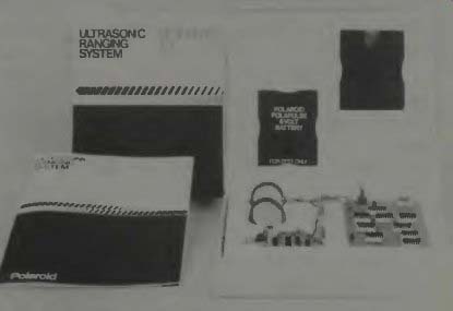
Fig. 1. The polaroid ultrasonic ranging kit includes two instrument-grade
Polaroid transducers, a modified Polaroid ultrasonic circuit board, two Polaroid
Polapulse 6-volt batteries, a battery holder, a wiring assembly and a technical
manual (courtesy Polaroid).
But there may be some disadvantages. If the robot is working in an environment where there is a high sound level, and a multipitch sound spectrum, then it might get signals which would cause malfunctioning and problems. It is possible to filter the sonic signals (as Polaroid does) so that most other tone signals or ultrasonic signals are not received in sufficient strength to cause alarm, but, in a machine shop, for example, where tooling, grinding, etc., are taking place, you will find spikes of ultrasonic energy all over the low frequency spectrum to 100 kHz or even into the low rf frequency range. Look at the block diagram of the experimental demonstration circuit board package of the Polaroid Ultrasonic ranging system in Fig. 2. The range of the Polaroid system is from 0.9 foot to 35 feet, and that ranging information is presented on a digital display. Of course one could intercept the signals to the display and use them to activate other devices if this is desired.
A hobby robot will, no doubt, use TV camera type eyes, a voice synthesizer for speech, and a multitude of sensor de vices to provide information as to where it is, what it is encountering, and what is around it. Some persons, talked to in the preparation of this guide, said that they find, in the larger toy stores, a multitude of electrically driven cars, trucks, tanks, and such, which make ideal starting units for robot development. Some, of course, start "from scratch" and built up from just an idea. Such was the origin of GARCAN which was illustrated in an earlier section.
John Cledhill discussed his robot in Robotics Newsletter, Sept. 1979. Some of what he said is interesting to us at this time. "It's surprising that most of the complexity of a computer (in robotics) is a result of the necessity of communications with humans. A dedicated, on-board robot computer doesn't have to have a keyboard, address/data light, etc., if you have a separate system for generating software. In my robot, decisions are made by a SC/MP-II microprocessor from National Semiconductor. But one could use the Motorola 6802.
My robot's basic senses begin with a bumper that encircles the frame and wheels. Eight microswitches provide input identifying if and where an object has been struck. The 8 microswitches for one 8-bit word are ANDed with constants by the computing section, so it knows which switches have been closed. The computer then knows what corrective action is necessary.
Since number 2 will be sonar using a National Semiconductor chip LM1812. The computer will tell the chip when to transmit and then time the echo response. Extreme accuracy is not necessary, as this will be used only to find out if there is anything in the field of view. Once something has been found in the field of "view", the bumper becomes the back-up device and will generate the operational signals causing whatever action is necessary.
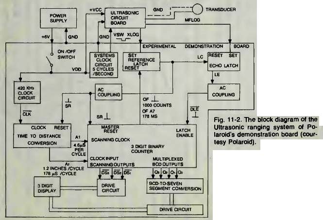
Fig. 2
This analysis and excerpt from that hobbyist's report gives us some indication of one way ultrasonic systems might be used in a very secondary role. With the Polaroid unit and with proper circuitry, there is no reason why ultrasonics can't be used as the primary control sensor. The Ultrasonic ranging system of Polaroid might be useful. With Ultrasonics your robot would not have to strike anything to get a signal that it was approaching something, or getting close enough to stop moving or to turn away!
MESOTECH SYSTEMS LTD of Vancouver, B.C. makes a mode-952 Bottom-Scan-Profiling-Sonar with some features that might be useful to think about in connection with robotics applications. Of course the transmission of sound in water is somewhat different than the transmission of sound through the air, especially with regard to the frequencies used. We know that some frequencies propagate very well through water and others do not. We have no correlation for the propagation of these sound frequencies through air versus other frequencies which might be used. One might have to do some experimentation in this area. In any event, the sonar system under discussion is one which, from a single location, records a profile of water depths along a particular line of bearing. By changing the orientation of the transducer, pro files of several lines can be made.
This transmitter unit, the sonar head, transmits a narrow beam, high frequency acoustic pulse. The narrow beam is swept through a vertical plane, and, of course, the returning echoes are timed which gives the distance to the reflecting surface, which, in this case, is the ocean, channel, or harbor bottom surface. The complete system consists of the sonar head and the recorder case (which charts the bottom profile) and a 100-foot cable which connects the two units. Inside the sonar head are the acoustic transducer and the stepping motor which sweeps it. There is also an inclinometer which senses ships rolling, and the sonar transmitter and receiver circuitry.
The beam width in this unit is only 1.5 degrees, but its operating frequency is 360 kHz. It ranges to 160 meters with an accuracy of plus or minus .5 percent. Its angle measurement resolution is plus or minus 0.75 degree.
What is very interesting to us in robotics is the narrow beam concept of this unit. If such an acoustic device could be used in air, on a mobile robot, one could have a device which could accurately measure objects around it, and distances to them. The use of a stepping motor for the sweep also means that a microprocessor memory unit would be able to deter mine exactly in what direction the transducer head was pointing. In essence, we might obtain good or better accuracy than with a radar unit.
In some applications the Mesotech type unit may be used to keep track of underwater robots that are free to move in their environment, yet are under observation and control of a parent ship on the surface above. No cables are necessary to send control signals. Coded acoustic pulses can convey this information, as well as give range and bearing from the mother ship's reference position. The TV signals, however, do at present, require cables. It could be a problem knowing where your underwater robot was, and also communicating with it, unless you have very good sonar systems in use.
There are some frequencies which tend to "channel" in water and go a long way with a reasonable amount of power. "Windows" these frequencies are called. It is safe to assume that 360 kHz is such a sonic window.
A RANGING SYSTEM USING LIGHT
One ranging system which uses the reflected light from an object to adjust a camera lens into focus has been incorporated into the Japanese Sanyo Autofocus Camera Control System, in their ES-44XL-VAF super 8 camera. In this system, basically, two mirrors are used to see the object through the camera window. The light from the object is reflected through a prism onto a photo-electric detector element which, in turn, sends the voltage generated from its two elements into a circuit which measures the balance. When the balance is exact a signal is generated which is then compared to a signal which indicates the position of focus of the lens. If the two signals are not in agreement, a small motor is energized which then adjusts the focus. Figure 3 shows a skeletonized view of the system.
The use of a prism to focus the light rays onto a silicon type photodiode (actually two of them) is easily seen in the illustration. The use of the prism to get two beams of reflected light can be better understood in the inset of the figure. I titled this section Ranging Systems. This system would calculate a range to an object by use of the focus information.
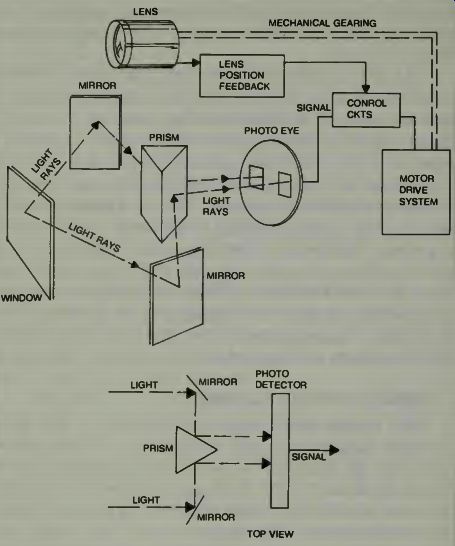

Fig. 3. A sketch view of Sanyo's autofocus system for cameras.
There would be problems adapting this system into a robot for its eyes. You should have a good illumination level, and that is not always possible. Of course you might incorporate an automatic lighting system into the robot so that a photo-illumination bright light will come on when the robot starts to move about. Then, it could get a good reflection, even if this causes some temporary blindness in the people it confronts!