AMAZON multi-meters discounts AMAZON oscilloscope discounts
In section 4 we looked at the Cincinnati Milacron T3 robot. Now we want to consider this robot again with respect to some features which are pertinent to what we have been discussing. As a stepping off point for this section, let us examine Fig. 1 which is another view of this modern robotic arm for industrial type applications.
We should be pretty knowledgeable about what we are looking at. There is a base section, lower arm section, its rotary electrohydraulic driving motor, the upper arm section which is operated by a piston type linear hydraulic system, and finally out to the wrist and gripper which are also operated by electrohydraulic units. Notice that in the illustration the grippers are of the parallel movement type, that the jaws are shaped to accommodate round or similar shaped objects, and that the grippers have a small thin compliance sheet built into them.
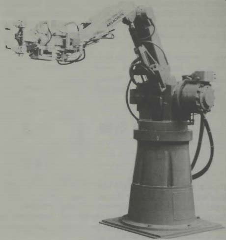
Fig. 1.The Cincinnati Milacron T 3 robotic arm (courtesy Cincinnati Milacron).
In an industrial application, of course, there can be a lot of dirt from the products, or processing of the products. In these locations and situations, of course, you would want the robot to be adequately protected by sealing, and with covers on the moving mechanisms so it won't acquire any debris which might cause premature wear, inaccurate operation, or excessive down time of the system. As you notice, the 1 .3 is so protected. It is also of interest to see the complexity of the wrist giving it the equivalent of a human's wrist movements.
In the specifications for this robot, we find that the servomechanisms use both the position feedback we have discussed and also a velocity feedback. The position feedback is through the use of resolvers which operate on ac, and a tachometer-generator which produces a voltage proportional to the speed of movement. These two feedback signals enable the servo-computer to adjust the movement and operation of every axis of the robotic arm to a smooth and fast operation.
You might want to go back and review section 4 for the operation and teaching method employed with this robot.
We have mentioned the velocity-of-movement feedback, but perhaps we have not specified just how fast such a robotic arm moves when it does a task for us. This Milacron robotic arm can move from one inch-per-second to as fast as 127.5 inches-per-second and this velocity range can be adjusted in increments of 0.5 inch-per-second units. Its precision-in location ability means that it can return to the same over and over with an accuracy of plus-minus .025 inch. A way of visualizing this accuracy is to know that it represents 1/40 of an inch. You know what a 32nd of an inch is, so tighten up a little on this distance and you'll have the 1/40th of an inch distance.
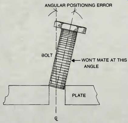
Fig. 2. A tight tolerance fit requires precision positioning.
There are some types of applications where tolerances must be even more precise. In fitting a bolt or a shaft into a tight tolerance hole, an accuracy of 1/64th inch or even better might be desired! Even then some wobble may be incorporated into the robot's wrist movement to cause the tight fitting object to go into the hole as it is supposed to. Figure 2 illustrates how just a small off-set can make it difficult if not impossible, to get a bolt or shaft into a closely machined hole.
Perhaps the problem of getting a servomechanism to have even greater than usual position accuracy on a repeatable basis will be solved, and the limit of such accuracy may astonish all of us! When we consider an industrial robot as shown in Fig. 1 we also want to be aware that this type unit can be programmed to perform a series of operations with one tool as its end unit and then change to another tool to do some other operation. The wrist connection must be such that a quick disconnect and quick connection can be accommodated, and with all the power connections necessary to make the new tool operate in whatever manner it is designed to operate. When we think about this for a moment we realize that there is more to a tool changing operation that is first apparent.
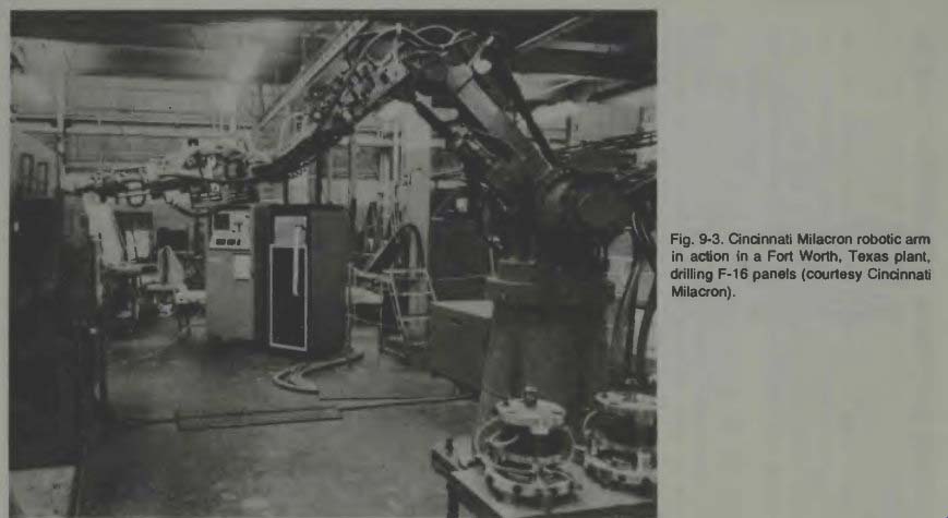
Fig. 3
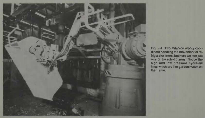
Fig. 4
One other item of information which we now should be aware of and which we have not mentioned prior to this is the concept of a rotary hydraulic actuator. They exist and they are rather common. They are much used in marine operations.
They can be precisely controlled to rotate small or large amounts and they have considerable power. If you are interested in going into this subject deeper, I suggest a good text on hydraulic engineering from your local library.
It is always interesting to see a robot arm in action. If you examine Fig. 3 you can get one idea of how this Milacron robot appears on location and in action. One other view of this robot in action can be seen in Fig. 4. What is interesting about this picture is that this is just one station of a two station operation. Shown is a refrigerator liner which is made of thin gauge plastic and due to its large size is difficult to handle.
One robot arm removes the liner from a moving conveyor and places it in a trim press, then it is removed from this trimming press by a second robot which again hangs it on the moving conveyor overhead. The two robots must work together in coordination and must know all about the orientation of the linear to insure it will be properly trimmed and will not be fed to the next station up-side-down!
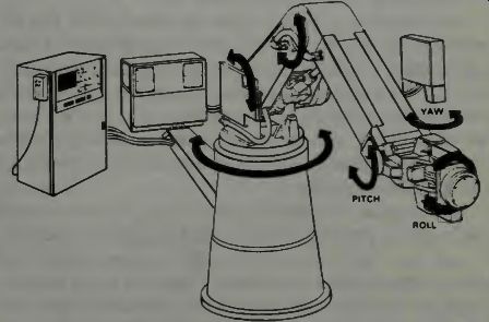
Fig. 5. The T 3R3 Milacron robotic arm has a three-roll wrist. Compare this
arm construction to that of Figure 1 (courtesy Cincinnati Milacron).
THE QUEST FOR IMPROVEMENT OF INDUSTRIAL ROBOTS
Time marches on and improvements and breakthroughs in technology make possible concepts, ideas, and things which are almost incredulous. Improving an industrial robot may not be an incredulous feat, but it is worth some time and attention. And, like our mini and micro computers, robotic systems do improve as time advances. We will examine one such development.
Turn to Fig. 5 where the newest of the Cincinnati Milacron robots is shown. The immediate focus of our attention is on the new wrist development shown. This is a three roll wrist and if we look back to Fig. 1 we can see how the wrist complexity has been reduced in this later version. The upper arm and wrist are more slender and the powering units for the wrist and gripper are now mounted at the elbow joint of the upper arm. Physical linkages are contained inside the upper arm so that it is very clean in appearance.
It is of some importance to discuss the use of such a robot on an automobile assembly line such as at the General Motors Lakewood, Georgia plant. The robots are used to spot weld about 9600 welds per hour on as many as 48 car bodies which pass its station each hour. 200 welds per body are accomplished, and that means the robotic arm must operate quickly and precisely to do this job. Four such robotic arms are used. With a capability called tracking the robotic arm can move as the car body moves so that the welding takes place in a continuous fashion, and the conveyor line never has to be stopped. It is said that it makes no difference whether the line speeds up or slows down, the ability of the arm to operate faster or slower, going to the precise positions where the welds are to be made, is accomplished by position sensors which are attached to the conveyor belt and electrically inter faced with the robot's computer control center. Thus we learn even more about how such a robot is used and how it operates in the industrial application. With these position sensors on the conveyor belt, a continuous signal is sent to the robot's brain telling it the exact position at all times of the car bodies.
Inside the robot's computer brain is a section which can take this feedback signal and use it to the previously taught welding program and the arm's position so that it moves to new locations at the proper speeds to compensate for the car's movement.
THE MILACRON THREE-ROLL WRIST
The new wrist design which we examined in Fig. 5, and which is called the three-roll wrist, is shaped like a sphere about 8 inches in diameter and has built into it three roll axes. Two of these axes work together to give the robot arm 230 degrees of pitch (up and down) and 230 degrees of yaw (side to side) motion. The third roll axis is aligned so that it permits continuous rotation of the wrist with whatever tool may be affixed thereto.
Once again, with remote drives to make the wrist function, resolver position feedbacks and tachometer feedbacks on each axis, and each axis controlled independently by its own servomechanism, the arm functions with a high degree of precision. Its positional accuracy is within .020 inches. It is quite an accomplishment to move that mighty arm around so quickly and yet to within that small of an error of a defined point in three dimensional space. Please note that many of the industrial robots achieve this accuracy, or better accuracies than this. The discussion of accuracy is in connection with the generic robotic generation of our time, not any single system, although we are examining the Milacron as one example of a fine robotic arm.
THE ROBOTIC EYE OR OPTICS CONTROL
I was delighted when I first saw the small robot mounted on a four wheeled cart that was like a child's wagon. It was self propelled and steerable, and carried the robot (shaped some thing like the upper half of a human torso) along with astonishing speed. The head turning to look at various scenes around this robot. I was told that this was an inspection robot which was patrolling the yard of an industrial complex. It moved fast and saw everything and then relayed, through a special microwave or ultra high frequency channel, the information about what it was seeing back to a central control station where the guiding mechanism-a human being-was involved with steering, stopping, starting, and evaluating the picture received from this remotely controlled robot. Figure 6 illustrates the general concept of this unit.
The robot has no hands or arms. Its purpose is simply to run around the area's complex looking at everything and relaying the information back to control-central. It worked much faster on patrol than a human might, and in case there was danger from penetrators, its metal armor could shield it while it informed its master what was going on. It never tired, and aside from a pit stop now and then for a new battery supply, it could patrol constantly and for indefinitely long periods of time. Its eye protruding from the front of the round head actually is the snout of a TV camera and on its head protrude two antenna, one for transmission and the other for reception of the required TV and guidance signals. Some plaything! But it has its purpose and can do a job for its owner. It never tries to fight back if it runs into culprits, so it doesn't need guns and it may not even need a voice although it would be an easy task to incorporate a speaker which would relay its owners voice if questioning or demanding were in order.
Let us now proceed to investigate some hard facts about just what robotic eyes are, how they work, and what their capabilities and limitations are.
There is no way at present to provide a robot with all the visual capabilities that a human has developed. To elaborate on this idea, think of all the various scenes that you can immediately identify. Think also how the human brain can identify size and shape and coloring and structure and composition and distances. Can a robot's eyes do this? Can it do it for all the countless pictures which the human brain has in its storage bins?
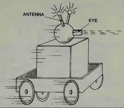
Fig. 6. A remote-controlled "seeing eye" robot.
What we are saying is that perhaps the hobbyist's dream of having a robot, with eyes roll down the street and say good morning to Mrs. Smith and Mrs. Jones and Candy and Jim as the robot sees them and identifies them, seems unlikely. Of course, if we provide the robot's brain with pictures of these people and it can then compare the picture it sees with what we have given it, it might. Polaroid and Bell Labs have both been working on computer recognition.
In the industrial situation we find it very desirable to give a robot some eyes. If it can identify a particular part amongst many parts passing by on a conveyor belt, that can be most useful. If it can watch and follow and adjust for parts mis-orientation and placement and such, that also can be most advantageous. So there are many prominent companies en gaged in developing robotic eyes for use in the industrial scene as we shall see. For the hobby scene, it may be some time before the use of eyes on a robot becomes worthwhile to incorporate. The basic question is what advantage is there to giving the robot some vision? The remote-controlled robot might be clad in asbestos armor for going into a flaming floor of a home or office or warehouse and seeing what is there, and perhaps accomplishing a rescue attempt. For underwater robots, one must certainly have some vision transmitted to the control center so that a human might send commands to make the robot fix or adjust things underwater. The seeing robot can be very useful if it extends our own vision capabilities. Visual feedback may also help to eliminate the stringent accuracy requirements in the workplace. If the robot can see what it is doing, the arm can adjust the manipulator so that the task is accomplished.
Seeing as we use the word here, may not be precisely the same as seeing related to the human optic operation.
Let us examine what is meant by seeing in an industrial application. A robot is going to be able to reproduce what it sees in a digitized form so it can compare it to a previously saved picture and make adjustments in the arm. Examine Fig. 7.
The camera is pointed where the object is to appear and instructed to follow, or keep track of it. When a picture is obtained, it must be analyzed by the microcomputer and identified. If the part is mis-orientated a match does not occur.
The camera may be moved slightly to see if it is the camera angle which is responsible. If this is not the case, then the system must order the robot's hand to move the object around to see if the proper orientation can be obtained. If the proper orientation cannot be obtained, the microcomputer decides that this object has no business being there and will instruct the gripper to separate it for human inspection.
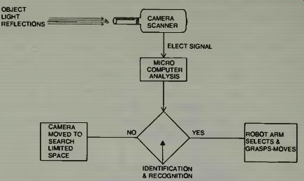
Fig. 7. A basic block diagram of a vision system for a robot.
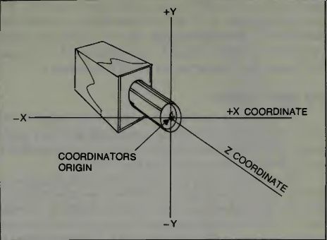
Fig. 8. The camera coordinates of a system for robotic vision.
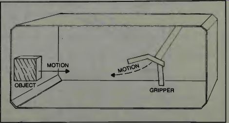
Fig. 9. An imaginary monitor screen shows the "object" and the
gripper, and the motions of each.
Assume that a robot is using visual feedback to insert a guide-pin in a hole. To provide position information, the system will track four features of the scene; the hole, the tip of the pin and both sides of the pin. These are three totally different features. A dark blob is the hole. A complex curved line is the pin bottom edge, and the sides are straight vertical lines. The computer knows there must be a certain specific relationship between the curve and the blob, and the straight lines and the blob, and these must occur simultaneously. It then steers the robot's hand to try to accomplish this.
We are now confronted with getting some dimensional coordinates of the object which the hand is to take hold of.
Notice that the Z coordinate in Fig. 8 is the distance from the camera to the object. The X coordinate is the left right position, and the Y coordinate would be the forward back position. Imagine an object coming along a conveyor belt. If the camera were exactly aligned, the object would move from - X direction, through zero, and on out to the +X direction. The Y coordinate might be zero all this time. The Z coordinate (the distance) will change as the object moves directly under the camera and then away from it.
Imagine the picture that might be seen by the camera. If we have a monitor screen to look at, we might see the dark shape appear at one side of the screen and vanish off the other end unless the gripper appears to grasp it. A pictorial representation of the situation is given in Fig. 9. The computer, which is directing the operation of the robotic arm, will have been informed where the objects are to appear, the shape they should have and of course their existence as denoted by a darker blob of light reflected from the object than from its conveyor. If the object is not in the position it should be in, then this might be a signal to put it in the proper position. If it does not have the shape the computer thinks it should have then the computer might stop the conveyor and have the robot re-position it. If this cannot be accomplished the computer will decide that the part is not useful and discard it.
THE VISION WINDOW
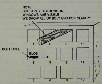
Fig. 10. Robot-Vision "windows" depicted on an imaginary display
monitor. NOTE BOLT-ONLY SECTIONS IN WINDOWS ARE VISIBLE WE SHOW ALL OF BOLT
END FOR CLARITY
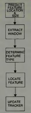
Fig. 11. A robot-vision tracking system block diagram.
The computer cannot look at the whole screen all the time, so it finds it convenient to establish windows to get useful information concerning the object it is looking at. We might illustrate this as shown in Fig. 10.
The computer finds the hole blob where it should be, in window 2, and moving in a straight line toward window 5. It finds the bolt blob occupying window 1, window 4, and window 2. If the bolt were positioned properly, it could not be seen in window 4 at the same time that it is seen in window 1.
So the computer has something to go on to adjust the bolt's orientation. If necessary the computer can shrink or expand the size of the windows.
Many robotic eyes are light-sensitive cells arranged in a matrix. Each cell produces a signal whose intensity or polarity is a function of the amount of light falling on it. The light-gathering unit is the lens system in front of the matrix.
Figure 11 shows what the seeing robot has to do in a situation where it is required to follow an object or track its position. The computer identifies a feature of the blob that it sees. This feature may be the round segment of the hole. It could be the straight parallel lines which tell the computer it is looking at the bolt. It could be the shaped curve of the bolt tip, which is a different curve from that of the hole. The system tracks the feature by causing movement of the robotic arm, hand, or camera.
Scanning a matrix window and producing a voltage ac cording to the various shades of color from white, then digitizing this voltage and giving that information to the microcomputer is how the computer can get the information it needs from the robotic-eye system. The computer can then compare this digitized signal with memorized signals in its memory bank, and do something as a result of this comparison. Figure 12 may be helpful. Each window may be scanned separately in a high resolution system. The scanning process is just like standard TV technology.
USING THE MATRIX EYE
Scanning a light sensitive surface with a beam is one method of converting light into voltages. A better way is to have a grid which is composed of an incredible number of small wires running vertically and horizontally and then tap ping into this matrix by means of a computer like system and reading the voltages produced at each cross-wire junction.
General Electric has such an eye and we show it in Fig. 13.
General Electric calls their new camera the TN 2200 and it uses a charge injection device, (CID) to convert the light energy into an electrical signal. The system resolution can be enhanced by use of an appropriate system of lenses.
With the grid system the X and Y coordinates of the object will be defined by the electrical charge at the junctions in the grid field. The Z coordinate can be determined by the intensity of that charge.
SOME BASICS OF ROBOTIC-VISION COORDINATE DETERMINATION
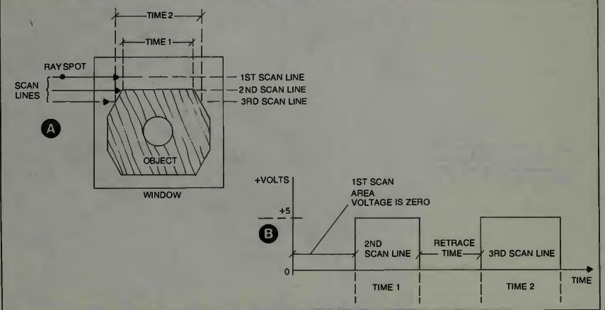

Fig. 12. The scanning voltages for three lines of a robot-vision scanning
system. A hypothetical case.
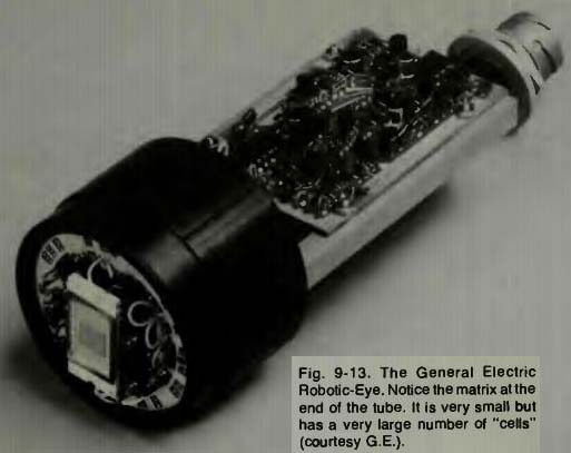
Fig. 13.
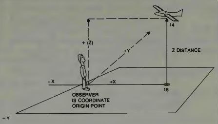
Fig. 14. A three-dimensional airplane position situation.
Figure 4 shows the military problem of trying to hit an airplane with an artillery shell. The first task in that problem is trying to define the position of the airplane in a three dimensional world. That is, its altitude, its azimuth, and its distance. Here we assume that the observer's position is the origin of the coordinate system. The airplane is flying along a path which is directly on the X axis, and it is approaching the observer at a constant altitude Z. As shown we could say the plane has at this moment an X coordinate of 18 units, a Z coordinate of 14 units and zero Y coordinate. The TV camera can certainly provide information on two dimensions of that space, but what about the third measurement. How can a TV camera give us range information? The human eye is able to perceive distance because two eyes are used. There is some distance between them, and the brain can perform the necessary calculations (and we aren't even aware it is doing so) to tell us the distance of an object.
This system is called triangulation and, the answer, of course, yes, it can be used in robotic applications. Let us examine Figs. 15 and 16. Figure 15 uses a laser and one camera; Fig. 16 uses two TV cameras. They examine a given point or object through identical angles. The base distance between the cameras is known. A side and two angles are known. The other two sides can be determined. The range is then calculated. The angle is how far the head is turned. Polar coordinates are converted to Cartesian (X,Y) and then the elevation (Z) is found.
You will recall that we have to track the recognizable edge or curve of a particular shape. Our range finding system must be able to differentiate, in perhaps fractions of a millimeter, the distances to various sides of, say, a hexagon shaped nut. Whereas a camera might not be capable of this as Radar and Sonar are.
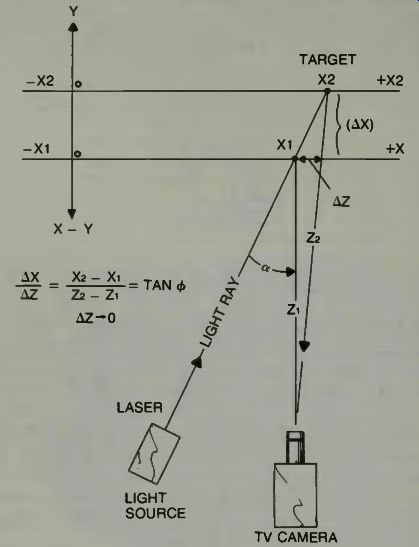
Fig. 15. One concept of distance measurement using a TV type camera imaging
system.
THE RECOGNIZER, THE COMPUTER, AND THE CONTROL SYSTEM
The recognizer is that part of the system which identifies some characteristic of the object. It may be the outline, reflectivity, position, or something of that nature. Figure 17 is a block diagram. If the recognition is satisfactory the computer orders the control system to do something to the object.
If the recognition is not satisfactory then a new look is ordered. The system tries to identify the object as something which should be there, even though it doesn't have exactly the right position or orientation.
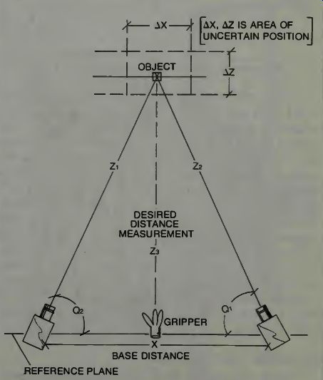
Fig. 16. Triangulation measurement of range using two TV cameras.
THE SYSTEM CONCEPT OF G.E. OPTOMATION
We have mentioned the G.E. CID video camera.
Examine it in Fig. 18. It is not very large and it differs in configuration from the camera we have examined in Fig. 13, but the operation is the same. The basic concepts underlying the Optomation video system are three.
The first is visual observation with the CID camera.
Because it has a very stable coordinate, system, it can effectively super-impose a stable and repeatable measurement grid over the object under observation.
The second is the recognition of the object by the extraction of some of its key features.
Finally, based on observation and recognition, some kind of decision is arrived at by the computer controller.
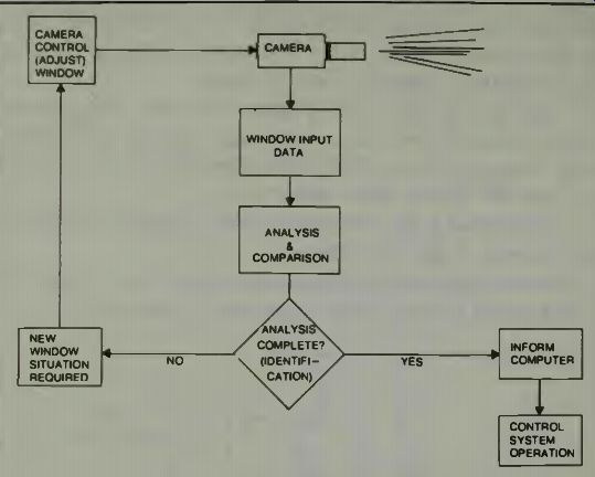
Fig. 17. Robotic-vision recognition system, block diagram.
In the system development a strategy has been employed which says that there will be two levels of viewing. In the Level I system operation the objects are placed in the camera's field of vision in a carefully pre-determined orientation. The system then obtains such information as length, height, area, and relative or absolute location. The relative location may be the position of the object with respect to the robotic gripper. The absolute location may be the object's location with respect to camera. In this system simple shape recognition can be accomplished by comparison of the viewed object with a feature set which has been memorized from a previous image. If desired a multitude of electronic windows can be used all at the same time, to make many measurements simultaneously. The Level II system operates on all the things the Level I does and also can examine randomly oriented objects.
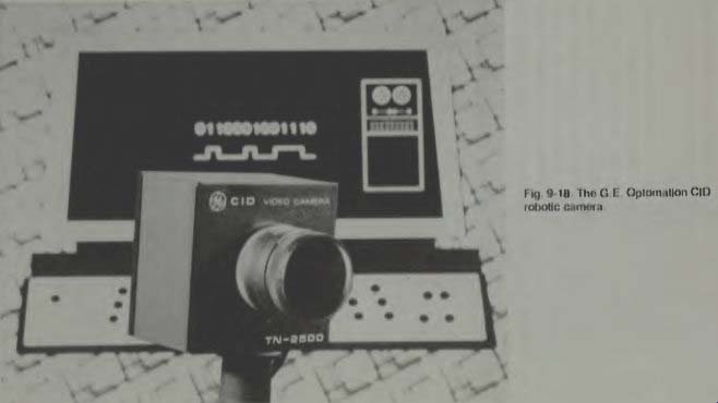
Fig. 18
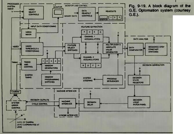
Fig. 19
THE CAMERA ROBOT INTERFACE
The interfacing unit feeds the robotic control system signals from the camera. The G.E. interfacing unit requires only that a cycle control pulse be sent to it. This pulse informs the interfacing unit that the camera data is ready to be accepted by the computing section. It also causes a new frame of video to be put into the feature extraction section. This, in turn, causes a new set of measurements to be taken.
There are 8 separate decision outputs available to the computer and control system from the interface unit. These may be in either one of two forms. They may be in TTL positive true logic levels or a one amp, 60 Hz control signal of either 110 or 220 volts, present when the output is true. A strobe interface is provided in this system to synchronize a stroboscopic lighting system with the input cycle.
DECISION GENERATION IN THE OPTOMATION SYSTEM
The contents of the decision state registers provide input data for the decision generation function. These registers are updated each time a measurement cycle is per formed. Notice how the camera is used in this robotic application. It is providing both measurements of position and recognition of objects in its field of view.
Going to the decision registers we note that a variety of output decisions can be generated from the input decision states. A part may be rejected, or selected, on the basis of only height measurement. It can be rejected if the height is too large or too small. A part may be rejected because its width and total area are not within specifications.
A delay function is also available and output decisions may be delayed by as much as 255 measurement cycles. The delay interval is determined by an 8-bit binary number which can be set by the human programmer using another system of multipole switches on the programming panel.
In Fig. 20 we examine the system's control panel. At the top are the multipole switches and the top section is labeled "Control Panel". On the second broad row the first unit is the decision logic panel and next to it is a data readout panel. This panel shows the decision outputs, the binary values, the channel routing and a section to compare results and the decimal value of the binary readout. In the third row down, on the left, is shown the feature control section and the Channel 1 and the Channel 2 blocks. On the right of this section is the sequence step constants section. On the bottom row we find the section for window control.
OPTOMATION SYSTEM OPERATION
The PN 2303 system has seven primary modules as you can see from an inspection of Fig. 19. These can be designated as; the camera unit, the input data conditioning unit, the feature extraction unit, the data analysis unit, the decision generation unit, the machine interface unit, and the monitor and control unit.
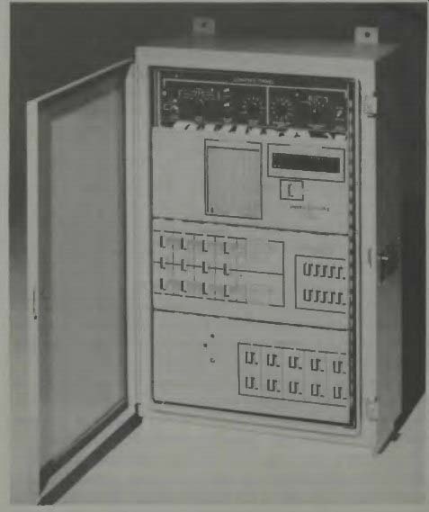
Fig. 20. The G.E. Optomation system control panel.
The camera unit is a logical starting point. It has a CID eye which means that it is composed of a mosaic of solid state light sensitive elements called pixels. The TN 2200 of Fig. 13 has 16,384 pixels, and the TN 2201 has 14,364 pixels.
Pixel time is the time required to scan a single pixel or light sensitive point. Pixel time for the G.E. TN-2200 camera is 10 clock periods.
Frame time is the time required to scan a full array of CID elements and it includes the blanking time. The TN-2200 frame time equals 17,688 pixel times and the TN-2201 frame time is equal to 16,608 pixel times. The line time is that time required to scan a single line of pixels and it includes the blanking time. For the TN-2200 it is 134 pixel times and for the TN-2201 it is 48 pixel times.
As used in the schematic diagram the X,Y, and Z axes are the same as an oscilloscope's axes. X is left-right, Y is up down, Z is bright-dim.
As we develop this subject we will be seeing some abbreviations, and so definitions of them will also be useful here. TTL is transistor-transistor-logic. LRR is line re-read.
Inhibit Input is abbreviated II. EOL is end-of-line and refers to a CMOS output of the camera that goes negative when the last element in a line is selected. EOF stands for end-of-frame and this is similar to the EOL except that it refers to the last pixel of the frame. EOL and EOF are used to designate retrace. STROBE is flash lighting.
In the TN-2200 unit the pixels are located just 0.0018 inches apart from center to center. The camera will accept standard C mount lenses which have a fixed back mounting flange length of 0.69 inches. The camera uses plus and minus 15 volts dc at under 50 milliamperes, and there is a 12 conductor cable used to attach the camera to its ancillary equipment.
There is a relationship between a lens picture size and the actual size of an object. The camera under study at the moment has a chart relationship which defines the size of the object as seen by the camera in terms of a ratio of object size to distance. The focal length of the lens is the factor which governs this ratio, as follows:
Focal Length mm inches
4.5 0.18 6.5 0.26 9 0.35 12.5 0.50 16 0.63 17 0.67 25 1.0 35 1.4 50 2.0 75 3.0 100 4.0 Object Size/Object Distance 1.3
0.89
0.65
0.46
0.37
0.34
0.23
0.17
0.12
0.08
0.06
To view a 6-inch object at a 4-foot distance, the object size/distance ratio is 0.5/4 = 0.125. Therefore, a 50 mm lens is appropriate for this application.
The video output signal of the camera can be converted to a TTL level signal with a threshold anywhere in the gray scale required. A simple conversion is shown in Fig. 21.
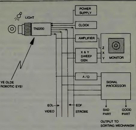
Fig. 22. An industrial inspection system using a G.E. robotic eye. The speed
o scan is chosen to match the signal processor requirements, and is controlled
by setting the clock frequency. The decision as to whether or not the part
is good or bad is made by the signal processor which may be a mini-or micro-computer
based system. An analog to digital conversion will be required for the video
signal if it is to be processed digitally. In many systems a monitor view of
the object is useful. A view may be presented by amplifying the video to modulate
the Z axis of an X,Y monitor. The Z axis is the light intensity on the monitor
tube presentation.
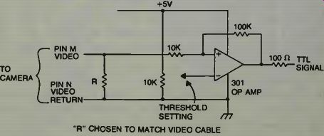
Fig. 21. A Video to TTL (transistor-transistor logic) signal conversion
circuit.
THE INDUSTRIAL VIDEO-INSPECTION SYSTEM
Figure 22 is a block diagram of the industrial video inspection system which shows us in a very simple arrangement how the robotic eye can be used gainfully. The signal processor shown is the computer. When it defines a part as bad, the robotic arm and gripper are signaled to reach out, grab that part, and convey it to the re-cycling area. If the part is good, the robotic arm may pick it up and send it along on another belt.
THE CID CAMERA CONSTRUCTION AND OPERATION
The signal readout is accomplished by a half-address scheme which is similar in concept to the core memory readout. The row scanner applies an address signal to a given - i row, resulting n a half-address condition on all the row pads in that row. (See Fig. 23.) The column scanner then sequentially applies the appropriate address signals to each of the columns, one at a time. This establishes a half-address condition on all the column pads in each column in turn. When all the columns in a given row have been scanned the row scanner increments to the next row and the process is repeated.
The result is a video signal in a television-like format.
This read-out is fast-usually 30 frames per second. Of course this output is analog in nature and so to use it in a microcomputer you have to feed it into an analog-to-digital converter. There are many types described in the current literature. If the signal is to be used directly by a robotic control system, the converter in Fig. 21 can be used to digitize it. The use of a video system for measurement of parts size and shape can produce really good accuracy. In the system described, it is claimed that an accuracy of up to 4 mils (0.004) inch can be obtained using microscope-optics systems.
FOLLOWING THE VIDEO SIGNAL
If we again refer to Fig. 19 we see that the video is immediately converted into a one-bit binary, black and white signal. The threshold level is adjusted electronically, but compensation for light variations can be made by adjusting the camera lens setting or the aperture opening. The balance of the equipment shown in the block diagram uses the binary signal as input except for the TV monitor, which uses the raw video. The system has a video mixer which permits the processed video to be superimposed on the normal image as an aid to setting up the system.
After the signals go into the feature and select switch where information from the window generators unit may be selected, the signals go the feature extraction section consisting of the accumulators. Let us examine the window feature in more detail.
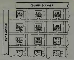
Fig. 23. The robotic camera eye's CID (charge injection device) row-column
matrix system (courtesy G.E.).
The windows may be of any size or at any position within the field of view. They may overlap if this is desired. The position of each window is programmed by means of a set of 8 switches which set up binary numbers equivalent to the column counts at the left and right edges of the window desired. They also set up the line counts at which the top and bottom of the window are to be located. The person looking at the monitor can superimpose a white level signal on the picture to show where the window is located. The output of the window generator is sent to the input of the feature extraction unit by means of a replaceable wire-interconnect header. Any of the five window generators can be assigned to any or all of the eight feature data accumulators, but only one window can be assigned to any one feature. As an example, window 1 may be assigned to both feature A and B, but windows 1 and 2 may not be assigned into feature A at the same time.
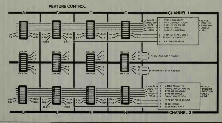
Fig. 24. The Feature Extraction Function control panel (courtesy G.E.).
WHAT IS FEATURE EXTRACTION?
We can gain some idea of what feature extraction is by examination of Fig. 24. What the feature extraction function does is to count the black and white pixels within the boundaries established by the window generators. The specific data to be stored in the eight accumulators is determined by the user. The type information which needs to be stored is selected by setting the switches on the control panel. Each of the small square blocks contains eight single pole switches.
In the block diagram of Fig. 20 we note that there are two accumulator channels which can be used to store information.
The reason for this is so that you can arrange for the storage of the absolute values in two sections and then you can get sums and differences by comparing these values if this is desired or necessary.
The feature control unit with all of its switches does permit a great deal of flexibility. For example, you can obtain your choice of video polarity which can be important depending on the background of the object under inspection. You can also select either smoothed video data or raw video data.
To find the position of the object in the space viewed you can check either the position of the object in the window section or the edge of the object in the window.
To measure size the count direction will determine whether measurement will be made along the X axis or the Y axis. You can choose whether you want a linear count or a cumulative count. The difference is a linear count will give a width of the object along a single line within the window. If you choose a cumulative count, then you'll get the total area in the window. Total black and white pixels are in the two data accumulation units, one in each channel.
The contents of the feature data accumulators are time-multiplexed into the channel 1 and channel 2 output buses under the control of the 12 channel step program sequencer. This performs the total basic steering function of data for the entire system. Each feature data accumulator can be assigned as many as three program steps and any unassigned data effectively becomes zero.
THE DATA ANALYSIS SECTION
The data analysis function is accomplished by comparing the present data with the stored data. The contents of selected feature data accumulators are multiplexed by giving each a time slot into the output bus at each of the 12 program steps. An eight-bit bus conveys measurement values for each sequence step. These values are then sent to the data comparator in a sequence. At the same time another set of values which define the acceptance or rejection thresholds are sent from the twelve sequence step constants switches to the data comparator. The output signal is used to drive the mechanism which accepts or rejects the part.