AMAZON multi-meters discounts AMAZON oscilloscope discounts
Prab Conveyors, Inc. have developed the Versatran robot which may be operated by a microcomputer, and is similar, in its learning operation, to the Milacron which we have just examined. Prab robots are also designed such that they can be programmed with a type of memory drum control, that is, it is possible to insert pegs into a revolving drum in such a way that these pegs will close electrical circuits, and open them, in the proper time sequencing so that various desired operations of this type robot can be accomplished. Also, this type robot can be controlled by limit switches, switches which open circuits at extremes of movement, or when certain velocities of movement are reached. They also can cause an arm to stop moving by limiting it physically--a mechanical stopping method.
We have mentioned the palletizing operation of an industrial robot. Look at such an operation, using a Prab Versat ran robot in Fig. 1. We see the gripper holding a bale, in the upper left side of the illustration, the arm will move to deposit it onto the stack in the proper orientation for stability of the stack. At the extreme right of the illustration you can see the control panel which governs the movement of the Versatran arm. We might not necessarily associate this automated machine with the concept of a robot, such as we imagine from science fiction tales, but it is a robot in every sense except physical appearance.
We can view some other applications of this type robot in Fig. 2, where it has an arm moving from a shoulder section to make plastic automobile parts. Also, we can obtain another view of this machine in operation in Fig. 3, where it is serving a five-station machining system which produces 80# ring gears.
Each of these units has a microcomputer type brain that is programmed by teaching the arm the various positions it must reach, and the sequence in which it must reach them.
This is done by entering these desired positions, in the proper order, on the microcomputer keyboard. The software then causes the arm to move properly and in the most efficient manner to accomplish the desired objective.
Each machine must have feedback signals so that the computer can determine when a given limit of movement is reached. To do this, the machines are equipped with limit switches, potentiometers, various types of encoders (devices which can tell the computer how much a shaft has turned, perhaps by generating a pulse for each fractional rotational movement) and resolvers (a selsyn type of unit that generates an ac signal whose phase change is directly proportional to the amount the shaft has turned). Programs for this type robot are written according to the manual data input, and can be recorded on magnetic tape cassettes. Other computers may be used with these robots using a special interfacing unit. The users may write their own programs for the machine. The Prab Versatran robot can move to any of 4,000 points in space.
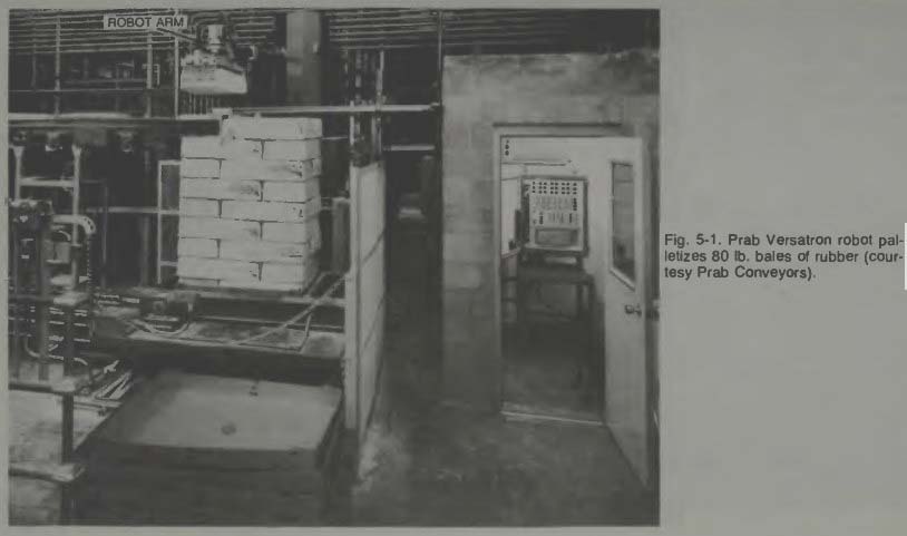
Fig. 1
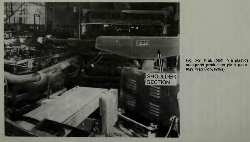
Fig. 2
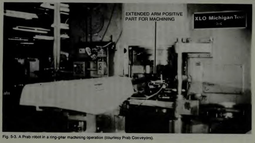
Fig. 3
AMAZON multi-meters discounts AMAZON oscilloscope discounts
CONCERNING ACCURACY OF A POSITIONING SERVO-SYSTEM
If we consider that a positioning system depends upon feedback as the control element in determining the system error or operative voltage, then we must look at those points from which feedback occurs. Recall that the operating or error voltage or signal for a positioning servo is derived basically from a comparison of an input signal command to the feedback signal which is generated from the position of the output member in question. If we assume that the command signal is simply a reference, then it is the magnitude of the feedback signal and its polarity or phase which will govern the effect of the two signal comparison, and thus govern the size of the error signal. Since the system power unit operates on the difference (error) signal, then the closer the output arm comes to the commanded position, the smaller the signal becomes. At some point this signal becomes so small that it will not cause power to be applied to move the arm further.
Where is the arm, or end appendage at that moment? Is it precisely where the command calls for, or is it within some tolerance, perhaps in the thousandths or even ten thousandths of an inch from that position? It cannot be perfectly positioned, thus it is within some tolerance.
Now, to gain a full appreciation for the complexity of these systems, note that when moving the end appendage, the system must reach many positioning points. First, for example, the arm must rotate to a given azimuth and stop there within the tolerance accuracy. Next the arm must extend to a given distance and stop there within a specification accuracy.
The end appendage may have to rotate about two axes within given accuracy specifications, and finally that end appendage may have to advance a given distance to within a specified tolerance. One notes, then, that errors in one element may effect the errors in another element. The errors may become cumulative, affecting the overall precision.
It has been argued that because the end device generates a feedback signal of its own that all other errors in the system's moving parts will be compensated for. However, there is still velocity and acceleration control that must also be within tolerance.
If a robot were used where it puts a bolt through a small tolerance hole, then the tolerance or accuracy of the robot's positioning of the bolt must be within the hole tolerance or better! In a case where the robot simply grasps something from a conveyor belt, such tight precision may not be necessary. The point is, it is the overall accuracy of the robotics system which, in large part, controls its cost! The more precise it must be the higher its cost.
PROGRAMMING AN INDUSTRIAL ROBOT: The Prab Versat
Through the courtesy of Prab Conveyors we will now examine their Versatran robot to learn how it is programmed.
General Information
Versatran robots combine electronic, mechanical and hydraulic action with flexible programming to provide general purpose machines capable of performing highly accurate and precisely controlled work functions. The object of the Versatran System is to drive the robot arm through a combi nation of motions and directions to perform a specific task.
The Versatran System is classified as a point-to-point automatic system. In a point-to-point system, program commands define specific positions or points in space to which the robot arm is to travel. The robot arm will move simultaneously in all axes (directions) requiring change to reach the defined position. In this way the most direct route will be taken to the new position. In the basic 3-Axis Versatran System, the Horizontal, Vertical, and Swing axes are provided. Optional wrist motions, including Rotate, Sweep, and Yaw axes, can be added to the tooling end of the robot arm to extend its work capability. Also a Traverse motion can be added when it is desirable to have the robot move from one location to another in performing its operation.
Instruction Codes. The model 600 Control Unit contains a Program Teach Panel which is used by the operator (programmer) to construct a sequence of instructions which direct the robot to perform a specific task.
A name is assigned to each instruction which in some way describes what the instruction does. Each instruction is made up of two (2) parts: The Function Command, which informs the Control Unit of the general task to be done; and The Function Value, which identifies specifically what action should take place. Coding the instruction is simply the act of combining a function command with a function value to pro duce a definite action.
Programming Rules. Programming or "teaching" the Control Unit is simply the act of establishing a sequence of coded instructions which directs the Control Unit to perform a particular task.
Programming is only as successful as the operators ability to understand the fundamental activities of the task to be performed. A good, sound structuring of a program is advisable to keep programs simple, clear and complete. The following five (5) step procedure to successful programming should be employed when preparing a program: RULE 1. Define the Operation: This is a brief description of the operation. The description should be prepared in a way which tends to identify the activities of the task.
RULE 2. Chart the Sequence of Events: This is a detailed description of the specific operation to be done. Each step of the operation should be listed in the sequence of which it is to be performed. (Depending on the complexities of the operation, it may be necessary to prepare sketches or flow charts in order to identify each step). RULE 3. Code the Program: From the detailed description, prepare a list of coded instructions in the sequence in which they are to be "taught". This list of instructions is referred to as a Source Program from which the Control Unit operates.
RULE 4. Teach the Program: This is the ENTRY of the Source Program into the Control Unit in the sequence established by the Source Program.
RULE 5. Check the Program: Once the program has been entered into the Control Unit, a review of the program instructions is advisable in order to assure that all instructions are in their proper sequence and the CONTROL UNIT will execute them properly.
Program Teach Panel. The Program Teach Panel is divided into five (5) basic categories. Prior to preparing any program, it is necessary for the operator to thoroughly under stand the purpose of each control.
(a) Operational Controls: These controls are used primarily for the operator to execute certain operational assignments such as teach, run program, erase program, etc.
(b) Manual Controls: These controls are used primarily for establishing, recording, and modifying the robot arm positions.
(c) Program Function Controls: These controls are used primarily for entering a set of coded instructions in a sequence that establishes a particular task for the robot to perform.
(d) Program Review Controls: These controls are used to execute each instruction, one at a time, in order to assure the program fulfills the intended task or to begin the program at a sequence other than with the first instruction.
(e) Program Editing Controls: These controls are used to alter or change the program or program sequence when corrections are necessary.
Operational Controls
The Operational Controls are used to assign certain responsibilities to the Control Unit.
These Controls consist of the Mode Select Key, Program Number Control, Program Erase, Lamp Test, and Cassette or Hand Held Teach Unit operation.
Mode Select Key Switch. The Mode Select is a turn key operated switch used to select the Auto-Run mode of operation, Teach mode of operation, Test Run mode of operation, or the Single Step mode of operation.
(a) Auto-Run: The Auto-Run position is the normal mode of operation when the robot is used to perform a specific task.
Placing the key in this position and pressing the Run Program button on the Operator Control Panel causes the robot to proceed with the task (program) identified by the Program Number Indicator.
(b)Teach: The TEACH position is used for preparing new programs or for checking and modifying existing pro grams. The new programs can either be manually entered with the use of the Manual and Function Controls, or electronically entered through the use of the Tape Cassette unit.
(c) Single Step: The Single Step position is used when it is desirable to review each instruction in sequence.
(d)Test Run: The Test Run position is used to check the movement and positions of the Robot Arm as established by the program instruction sequence. The Robot Arm is allowed to complete its cycle without interruption which may normally be required by the program.
Program Number Request. Selecting the PROG NUMBER Control will allow the operator to request any of the programs (within memory) to be run.
THERE ARE 64 POSSIBLE PROGRAMS WHICH MAY BE SELECTED. PROCEDURE: (a) Place the MODE SELECT key in the desired position.
(b) Press the PROG NUMBER
Control on the program teach Panel. (The lamp will light indicating the request). (c) Select the desired program number on the function keyboard (1-64). (d) Press the ENTER pushbutton under the keyboard (the PROG NUMBER indicator lamp will go off and the Pro gram Number selected will be displayed in the PROGRAM NUMBER INDICATOR). The Program is now available to be modified or run.
If the program selected is a valid program, the Mode Select key can be placed in the Auto-Run position to operate the program. If there is nothing in the selected program, turning the Mode Select key to any of the run modes will result in a code "130" display.
- CAUTION -
When operating the JOG control observe that the Robot Arm travels a path which is free of any obstructions. If the Robot Arm cannot be jogged to position without striking an object, release the JOG pushbutton and operate the manual axis request and axis direction controls to move the robot arm around the obstruction, then continue operating the JOG control until the robot arm arrives in position.
Program Erase. The Program Erase control is used to clear the program identified by the Program Number Indicator from memory. Once the program is erased all instructions and recorded positions are cancelled from the program.
PROCEDURE: (a) Place the Mode Select key in the TEACH position.
(b) Select the Program to be erased from memory by using the Program Number Request Procedure.
(c) Press three
(3) times in sequence: PROGRAM ERASE then ENTER. (Three times are required to prevent accidental erasures.
Lamp Test. The Lamp Test is a Control Unit exercise which scans all of the functions of the Unit. In this way a self-test operation can be performed. Each control button on the Program Teach Panel which normally lights will be lighted in sequence, beginning with the PROG NUMBER control at the upper left of the panel and continue to the right.
At the same time the Digital Indicators will display eights (8's) in each digit position. All light-operated switches on the Operator Control Panel will remain lighted during this test.
Normally this test is performed with the MODE SELECT key in the TEACH position.
- CAUTION-
Pressing the LAMP TEST during operating modes other than TEACH will cause the hydraulics to shut down and the operating program to stop.
Cassette & HHTU Connectors. The HHTU is used primarily to record and modify positions for precise control from a remote station. The HHTU utilizes a thumb pressure contact switch called a "dead man switch" as a safety measure for operating the robot arm while standing in the vicinity of its' working area. In the event unwanted motions are encountered which may cause damage or personal injury, releasing the "dead man switch" will cause the hydraulics to automatically shut down and immediately stop the arm motion.
(HHTU = HAND HELD TEACHING UNIT)
When the HHTU is connected to the Program Teach Panel all manual controls are automatically transferred to the HHTU. Two procedures are outlined which describe the method for recording new positions and for modifying existing positions with the use of the HHTU. PROCEDURE: (Recording Positions)
(a) Mode Select key to the TEACH position.
(b) Select the desired Program Number to be used.
(c) Establish and record the HOME position (position 1). Manual Controls
The Manual Controls are used for setting, recording, and modifying the robot arm positions. These controls consist of axis request, axis direction, record position, modify position, and next position number controls.
Setting the Position. Each one of the seven (7) possible axes has its specific request control. All axes are identified with yellow lighted pushbuttons for operator selection.
(a) Axis Request: When a change in a particular axis is de sired, the corresponding Axis Request pushbutton should be selected. Once pressed the Axis Request control will light as an indication of the request.
NOTE: If an incorrect axis has been selected, pressing the desired Axis Request control will automatically change to the intended axis.
(b) Axis Direction: The Axis Direction controls are identified as ADVANCE and RETRACT. These controls will move the robot arm in the corresponding direction relative to the particular Axis Requested. Depressing and holding the Axis Request control will result in acceleration to predetermined velocity, while tapping the control will move the axis one count for each tap of the control.
NOTE: Motion of the robot arm requires hydraulic assisted devices and therefore the HYDRAULIC UNLOCK and PUMP ON Control on the Operator Control Panel must be actuated.
When moving the robot arm with the Advance or Retract Controls, either control must be pressed and held until the robot arm arrives at the desired position. If the direction of motion is opposite the intended direction, operating the other Axis Direction control will provide the desired motion.
Movement of the robot arm to the desired position is a result of operating the individual Axis Request and Axis Direction Controls until their combined motions place the robot arm in the desired position, that position should then be recorded.
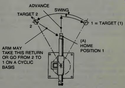
Fig. 4. Manual movement of the Prab Versatran robot arm (courtesy Prab Conveyors).
Recording the Position. Motion of the robot arm can be achieved by operating the manual axis request and axis direction controls in any of the MODE SELECT positions, other than the Single Step Position. However, to record a position the MODE SELECT KEY should be placed in the TEACH position.
SAMPLE 1: Assume the robot arm is in the position A as shown by the heavy solid lines of the drawing in Fig. 4. The objective is to record the two positions indicated by the "x". PROCEDURE: (a) Place the MODE SELECT key in the TEACH position.
(b) Activate the hydraulics.
(c) Select the desired program number which is to be used.
(d) Select the HORZ Axis Request and operate the ADVANCE CONTROL until the arm is in the desired out ward position.
(e) Select the SWING Axis Request & operate the ADVANCE Control until the arm is over the target. (1)
(f) Press the RECORD POS control to record the position in memory (position indicator will display the position number just recorded.) (g) Select the Swing Axis Request and operate the RETRACT Control (if necessary) until the arm is directly over the second target.
(h) Press the RECORD POS Control to record the position in memory.
NOTE: Always attempt to record position number 1 (A) as the HOME POSITION. Next Position Number Request. The Next Position Number control is used to select any particular recorded position within the program. Requesting a Next Position Number can only be done in the TEACH mode of operation.
PROCEDURE: (a) Place the MODE SELECT key in the TEACH position.
(b) Select the desired program number which is to be used.
(c) Press the NEXT POSITION NUMBER control (the lamp will light as an indication of the selection). (d) Select the desired position number on the keyboard. The Position Indicator will display the position number re quested and the JOG lamp will light.
Jog to Position. After making the Next Position number request, it may be desirable to move the robot arm to the position requested. A simple procedure for testing the movement of the robot arm between any two positions is provided below.
- CAUTION-
Keep in mind, the Versatran System is a point-to-point system. Consequently, the combined motion of the robot arm will take the most direct route from one position to the next.
Care must be taken to assure that the robot arm has a free path to travel. A JOG to Position, after making a position number request, will test the path of travel for the robot arm.
(a) Place the MODE SELECT key in the TEACH position.
(b) Select the desired program number to be used.
(c) Select the Next Position Number of interest.
(d) Press and hold the JOG switch button until the arm arrives in position. (When the robot arm arrives in position the JOG lamp will go off).
(e) Select the Next Position Number of interest and repeat step (d).
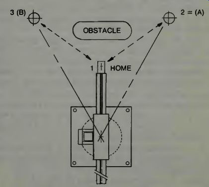
Fig. 5. Programmed arm moves around obstacle (courtesy Prab Conveyors)
The robot arm comes to an abrupt stop at the home position and immediately resumes its motion toward the next position (3) or (2).
NOTE: If any obstructions are within contact of the robot arm, releasing the JOG pushbutton will stop the motion of the arm. Travel between these two (2) positions cannot be accomplished and therefore the robot arm will have to be programmed to bypass the obstacle. (See Fig. 5)
Modifying the Position. After setting and recording a position in memory it may be learned that the particular position is not quite correct. The position can quickly and simply be modified without the need to change the program.
PROCEDURE:
(a) Place the MODE SELECT key in the TEACH position.
(b) Select the desired program number to be used.
(c) Select the Next Position Number of interest.
(d) Operate the Axis Request and Axis Direction controls until the robot arm is in the desired position.
(e) Press the MODIFY POS Control.
The Control Unit will accept the modified position in memory for the position number displayed on the indicator.
NOTE: If attempt is made to modify the position with the RECORD POS control, the requested position will not be modified. The Record Position Control will record only new positions.
Function Controls
The Function Controls are used for establishing and entering a set of coded instructions for the Control Unit to execute in performing a particular task. An instruction code is made from combining a general function command' with a specific function value. In this way, an instruction is provided to the Control Unit which directs a defined action. The following is a brief introduction to instruction code sets including examples using the instruction code.
Next Program Number: (Instruction Code NPN ..xx). When the Function Command NEXT PROG NUMBER is selected it is to be followed with a function value of no less than 1 and no greater than 64. The NEXT PROG NUMBER function command requests the Control Unit to go to another program in memory, while the function value (1-64) specifies which program in memory. When the Control Unit encounters an instruction code NPN. . XX, the Control Unit will execute the first instruction (sequence 1) of the program specified by the function value.
If it is desirable to repeat the same program, the NPN .. XX instruction code should contain the number of the program making the request.
EXAMPLE 1. Next Program Number (NPN. . XX) (a) Purpose: To repeat the same program.
(b) Detail: Identify the Program Number to run.
STEP 1: REPEAT THE PROCESS (c) Source Program:
-----------
Sequence .2. Function
Function .7. Instruction No. Command Value Enter Code BEGIN; Prog Number 1 . (.;PGN...1:) 1; Next Prog Number 1 • . (1:NPN...1:)
NOTE: A POSITION MUST BE RECORDED BEFORE ANY PROGRAM CAN BE VALID. NOTE: Although the source program of example 1 is a single instruction program, if "taught" to the Control Unit, it would be a perfectly acceptable program. The instruction to do program 1 would be repeated indefinitely until the program was stopped.
(d) Teach:
-Mode Select key to the Teach position.
-ENTER the Source Program in sequence starting with BEGIN.
-Record a Position (Press RECORD). (e) Check:
-Mode SELECT key to the SINGLE STEP position.
-Press the SINGLE STEP FWD Control to review the instruction.
Call Position (Instruction Code CPN XXXX). When the Function Command CALL POS is selected, it is to be followed with a function value no less than 1 and no greater than 9999. The CALL POS function command requests the Control Unit to direct the movement of the robot arm, while the function value (1-9999) specifies the particular position.
When the Control Unit encounters an instruction code CPN XXXX it will cause the robot arm to move in the most direct route to the position identified.
EXAMPLE 2. (Call Position CPN XXXX) (a) Purpose: To move the robot arm from one position to another and repeat the process.
(b) Detail: Identify the program number to be run.
STEP 1: START AT HOME AND GO TO NEXT POSI TION.
STEP 2: RETURN HOME
STEP 3: REPEAT THE PROCESS
NOTE: It is advisable to establish position 1 as the Home position. Position 1 is always the beginning position of any program. Also, it is good practice to place the Home Position (position 1) at a point which is out of the way. When the last position called in the program is the Home Position the robot arm will come to rest (out of the way) when a COMPLETE PROGRAM THEN STOP is activated.
(c) Source Program:
Sequence Function
Function Instruction
No. Command Value Enter Code
BEGIN; Prog Number 2 (.;PGN...2:)
1; Call Position 2 • . (1 ;CP N. . .2;) 2; Call Position 1 • . (2;CPN. . .1:) 3; Next Prog Number 2 • . (3;NPN...2:)
(d) Teach:
( i) Mode Select key to the TEACH position.
( ii) ENTER the Source Program in sequence starting with BEGIN. (iii) SET and RECORD positions 1 and 2.
(e) Check:
( i) Mode Select key to the SINGLE STEP position.
( ii) Press the SINGLE STEP FWD Control to review each instruction in sequence.
NOTE: If desired, the JOG switch button can be operated each time it lights to move the robot arm to each new position.
This practice is advisable to assure the operator that the arm has a free path to travel.
(f) Operate the Program: ( i) Mode Select key to the AUTO RUN position.
( ii) Press JOG to move robot arm to HOME (Position 1). (iii) Press RUN PROGRAM to execute the program.
NOTE: The program in example 2 will operate the Control Unit's predetermined speed. Faster or Slower operation will require instructing the Control Unit Velocity and Acceleration Codes.
Set Velocity: (Instruction Code SVL. .XX). When the Function Command SET VEL is to be followed with a functional value no less than 1 and no greater than 16. The SET VEL function command requests the Control Unit to direct the motion of the robot arm at a speed which is specified by the function value (1-16). The function values 1-16 are incremented from 1/2 IPS to 37 1/2 IPS with function value 1 representing 1/2 IPS and function value 16 representing 37 1/2 IPS. See Table (5-1) for a complete listing of velocity selections. (IPS = inches/per/second)
NOTE: Once a velocity value is selected, it remains in effect for all following movements until such time as a new value is selected. This is also true when the Control Unit transfers to another program in memory.
Generally, when specifying a velocity for the arm to move, an acceleration value should also be indicated.
Set Acceleration/Deceleration: (Instruction Code SAD. .XX).
When the Function Command SET ACC/DEC is selected, it is to be followed with a functional value no less than 1 and no greater than 16. The SET ACC/ DEC function command requests the Control Unit to direct the rate of change of speed of the robot arm to its maximum specified velocity. The acceleration/deceleration rates are specified by the function values (1-16) following the function command.
The function values (1-16) are incremented from 15 inches/sec/sec/ to 600 inches/sec/sec/ with the value 1 representing 15 inches/sec/sec/ and the value of 16 representing 600 inches/sec/sec. See Table 5-1 for a complete listing of acceleration/deceleration selections.
It is common practice, and recommended, that the function values of velocity and acceleration are referred to with the velocity value first and then the ACC/DEC value last.
(i.e., the values 5/4 represent velocity 5/acceleration 4). In this way, good communications with others involved with the program will be maintained.
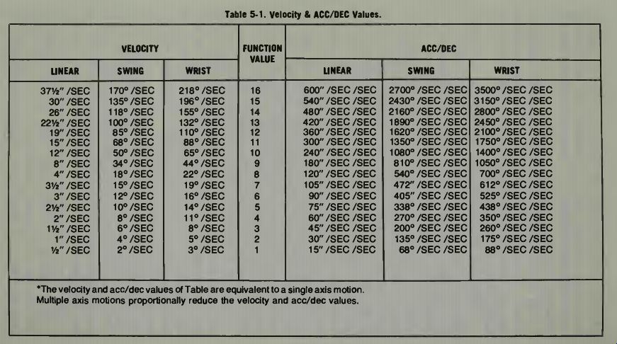
Table 1 --- *The velocity and acc/dec values of Table are equivalent to
a single axis motion.
Multiple axis motions proportionally reduce the velocity and acc/dec values.
The velocity and acceleration instructions (SVL. .XX and SAD. .XX) should generally precede the CALL position instruction (CPN XXXX) when movement to that position requires velocity and acceleration changes. When no VEL or ACC/DEC is specified, the Control Unit will resort to the present values of 5/4 as in the program of example 2.
NOTE: Once an ACC/DEC value is selected, it remains in effect for all following movements until such time as a new value is selected. This is also true when the Control Unit transfers to another program in memory.
EXAMPLE 3: Set Velocity & Set ACC/DEC (SVL. .XX & SAD. .XX) (a) Purpose: To move the robot arm from Home position to another position and return home at a medium high velocity and acceleration.
(b) Detail: Identify the Program Number to be used.
STEP 1: MOVE AT MED/HI VELOCITY STEP 2: MOVE WITH MED/HI ACC/DEC STEP 3: START AT HOME AND MOVE TO NEXT POSITION. STEP 4: RETURN TO HOME STEP 5: REPEAT THE PROCESS (c) Source Program:
--------- Sequence Function Instruction No. Command Value Enter Code BEGIN; Prog Number 3 (.;PGN. . .3:) 1; SET VEL 12 • . (1;SVL. .12:) 2; SET ACC /DEC 10 • . (2;SAD. .10:) 3; CALL POS 2 • . (3;CPN. . .2:) 4; CALL POS 1 (4;CPN. . .1:) 5; Next Prog Number 3 (5;NPN. ..3:)
(d) Teach: ( i) Mode Select key to the TEACH position.
( ii) ENTER the Source Program in sequence starting with BEGIN. (iii) SET and RECORD positions 1 and 2.
(e) Check: ( i) Mode Select key to the SINGLE STEP position.
( ii) Press the SINGLE STEP FWD Control to review each program instruction in sequence. If desired, the JOG switch button can be operated each time it lights to move the robot arm to each new position. This practice is advisable to assure the operator that the robot arm has a free path to travel.
(e Operate the Program: ( i) Mode Select key to the AUTO RUN position.
( ii) Press JOG to move the arm to HOME (position 1). (iii) Press RUN PROGRAM to execute the program.
EXAMPLE 3: Set Velocity & Set ACC/DEC (SVL. .XX & SAD. .XX) (a) Purpose: To move the robot arm from Home position to the next position at a medium-low velocity and return Home at a high velocity, then repeat the process.
(b) Detail: Identify the Program Number to be run.
STEP 1: MOVE AT MED/LOW VELOCITY STEP 2: MOVE WITH MED/LOW ACC/DEC STEP 3: START FROM HOME AND GO TO NEXT POSITION STEP 4: MOVE AT HIGH VELOCITY STEP 5: MOVE WITH HIGH ACC/DEC STEP 6: GO HOME STEP 7: REPEAT THE PROCESS (c) Source Program: Sequence No. BEGIN; 1; 2; 3; 4; 5; 6; 7; Function
Function Instruction Command Value Enter Code Prog Number 31 • . (.;PGN...31:) SET VEL 6 • . (1;SVL. ..6:) SET ACC /DEC 6 • . (2;SAD...6:) CALL POS 2 • . (3;CPN...2:) SET VEL 14 (4;SVL..14:) SET ACC /DEC 12 • . (5;SAD. .12:) CALL POS 1 • . (6;CPN...1:) Next Prog Number 31 • . (7;NPN..31:) (d) Teach: ( i) Mode Select key to the TEACH position.
( ii) ENTER the Source Program in sequence starting with BEGIN. (iii) SET and RECORD positions 1 and 2.
(e) Check: ( i) Mode Select key to the SINGLE STEP position ( ii) Press the SINGLE STEP FWD Control to review each instruction in sequence. If desired, the JOG switch button can be operated each time it lights to move the robot arm to each new position. This practice is advisable to assure the operator that the arm has a free path to travel.
(f) Operate the Program: ( i) Mode Select key to the AUTO RUN position.
( ii) Press JOG to move the Robot Arm to Home (position 1). (iii) Press RUN PROGRAM to execute the instructions.
Round Off Position (Instruction Code ROP XXXX). When a function command ROUND OFF POSITION is selected, it is to be followed by a function value of no less than 1 and no greater than 9999. The ROUND OFF POS function command requests that the Control Unit direct the robot arm to the position specified by the function value.
However, motion of the robot arm to and from the specified position is accomplished at program velocity. As the arm approaches the position, the deceleration value of the pro gram is ignored, consequently, the robot arm arrives at the position still moving at maximum specified speed and abruptly stops. Further motion to another position ignores the acceleration value of the program and immediately assumes maximum specified speed.
SAMPLE 2 (see Fig. 5): The desired motion is to move the robot arm between position 2 and 3. However, direct motions between these positions would cause the arm to strike the obstacle in its path. It is further desired to move the arm between position 2 and 3 with a constant velocity. Rounding off the Home position (1) and passing the robot arm through this position can essentially achieve the desired motion.
EXAMPLE 4: Round Off Position (ROP XXXX) (a) Purpose: To move the robot arm between two (2) targets avoiding an obstacle in its path and repeat the process.
(b) Detail: Identify the Program Number to be used.
STEP 1: START AT HOME AND GO TO TARGET A. STEP 2: INITIALIZE VELOCITY (MED-LOW). STEP 3: INITIALIZE RATE (MED-LOW). STEP 4: CALL HOME. STEP 5: GO TO TARGET B. STEP 6: INITIALIZE VELOCITY (MED-HIGH). STEP 7: INITIALIZE RATE (MED-HIGH).
- STEP 8: CALL HOME. STEP 9: REPEAT
NOTE: According to the detail of example 4, the robot arm will move from position 2 to 3 and continuously operate between these two positions. Movement from position 2 to position 3 is done with a med-low velocity and the return to position 2 is done with a med-high velocity. Position 1 is set as the home position such that when the robot arm stops at the end of the program, it is in a position that should be out of the way of the work area targets A and B). Sequence Function Instruction No. Command Value Enter Code BEGIN; Prog Number 4 • . (.;PGN.. .4:) 1; CALL POS 2 • . (1;CPN. . .2:) 2; SET VEL 6 • . (2;SVL...6:) 3; SET ACC /DEC 6 (3;SAD. . .6:) 4; ROUND OFF POS 1 • . (4;ROP...1:) 5; CALL POS 3 • • (5;CPN...3:) 6; SET VEL 10 • . (6;SVL..10:) 7; SET ACC /DEC 9 • . (7;SAD...9:) 8; ROUND OFF POS 1 • . (8;ROP...1:) 9; Next Prog Number 4 • . (9;NPN.. .4:) (d) Teach: ( i) Mode Select key to the TEACH position.
( ii) ENTER the Source Program starting with BEGIN. (iii) SET and RECORD position 1 (Home), 2 and 3.
(e) Check: ( i) Mode Select key to the SINGLE STEP position.
( ii) Press the SINGLE STEP FWD Control to review each instruction in sequence. If desired, the JOG switch button can be operated each time the lamp lights to move the robot arm to each new position. This practice is advisable to assure the operator that the arm has a free path to travel.
(f) Operate the Program: ( i) Mode Select key to the AUTO RUN position.
( ii) Press JOG to move the robot arm to Home (position 1). (iii) Press the RUN PROGRAM switch button to execute the program.
Time Delay & Interlock Dwell Instructions (TDL NXXX & ILD..XX;ILD.10X). When the TIME DELAY Function Command is selected, it is to be followed with a function value that identifies the timer number to be set at no less than .1 second and no greater than 99.9 seconds. The TIME DELAY requests one of ten timers to be set for a specific period of time and immediately begin counting down to zero. The period of time can be selected from 0.1 seconds to 99.9 seconds in 0.1 second intervals. Choosing one of ten timers is accomplished by recording the first digit (most significant digit) of the four digit number as the timer number and the remaining three digits with the desired time interval: i.e., timer number 3 to be set at 6.5 seconds; the function value should be set as 3065.
The timers are numbered from 0-9. When using timer number 0, it is not necessary to specify the timer number prior to setting the desired time delay value: i.e., timer number 0 desired to be set at 6.5 seconds; the function value should be setas. . 65. The INTLK DWELL function command has two significant purposes; (1) Wait for external source command before proceeding, and (2) Wait for timer to time out before proceeding. The WAIT FOR EXTERNAL SOURCE Command is determined by the function values 1-32 following the INTLK DWELL selection. This instruction requests that the Control Unit sit and wait until a signal is received from one of the selected 32 input lines. When the selected input line becomes "true", the process will continue, until such time the program will be stalled; i.e., wait for part to get into position (assume position signal is received on line one); the function value should be set as . . . 1; when the part arrives in position, a signal will be sent on line one which informs the Control Unit to resume the program.
The WAIT FOR TIME OUT Command is determined by the function value 10 plus the particular timer number. This instruction requests the Control Unit stop the program until the specified timer reaches zero: i.e., wait for timer number 3 to time to zero; the value should be set as 103; function when timer number 3 reaches zero, the Control Unit will resume the program.
EXAMPLE 5: Time Delay & Interlock Dwell (TDL NXXX & IL D.XXX) Wait for Time Out (ILD.10X)
(a) Purpose: To move the robot arm to position 2 and wait for two (2) seconds and then move to position 3 and wait for two (2) seconds. REPEAT THE PROCESS. (b) Detail: Identify the program number to be used.
STEP 1: START AT HOME AND MOVE TO TARGET A. STEP 2: SET TIME (2 SECONDS) STEP 3: WAIT TIME STEP 4: INITIALIZE VELOCITY (MED-LOW) STEP 5: INITIALIZE RATE (MED-LOW) STEP 6: GO HOME STEP 7: GO TO TARGET B. STEP 8: SET TIME (2 SECONDS) STEP 9: WAIT TIME STEP 10: INITIALIZE VELOCITY (MED-HIGH) STEP 11: INITIALIZE RATE (MED-HIGH) STEP 12: GO HOME STEP 13: REPEAT THE PROCESS (c) Source Program: Sequence Function No. Command Value Enter Instruction Code BEGIN; Prog Number 5 • . (.;PGN. ..5:) 1; CALL POS 2 • . (1;CPN...2:) 2; TIME DELAY 20 • . (2;TDL. .20:) 3; INTLK DWELL 100 • . (3;ILD;100:) 4; SET VEL 6 • . (4;SVL...6:) 5; SET ACC /DEC 6 (5;SAD .. .6:) 6; CALL POS 1 • . (6;CPN...1:) 7; CALL POS 3 • . (7;CPN...3:) 8; TIME DELAY 20 • . (8;TDL..20:) 9; INTLK DWELL 100 • . (9;ILD.100:) 10; SET VEL 10 • . (10;SVL..10:) 11; SET ACC /DEC 9 • . (11;SAD . . .9:) 12; CALL POS 1 • . (12;CPN...1:) 13; Next Prog Number 5 • • (13;NPN...5:) (d) Teach: ( i) Mode Select key to the TEACH position.
( ii) ENTER the Source Program starting with BEGIN. (iii) SET and RECORD positions 1 (HOME), 2 and 3.
(e) Check: ( i) Mode Select key to the SINGLE STEP position
• ( ii) Press the SINGLE STEP FWD to review each instruction in sequence. If desired, press the JOG pushbutton each time the lamp lights to move the robot arm to its new position. This practice is advisable to assure the operator that the arm has a free path to travel.
(f) Operate the Program: ( i) Mode Select key in the AUTO RUN position.
( ii) Press JOG to move the Robot Arm to Home, (position 1), Fig. 5.
(iii) Press the RUN PROGRAM switch button to execute the program.
EXAMPLE 1: Interlock Dwell (Wait For External Source) (a) Purpose: To move the robot arm from target A through HOME to target B. Wait at target B until ready to accept payload and repeat the process.
NOTE: The program purpose would be to release the payload at the robot arm tooling end only when the receptacle is "ready" to receive the payload.
(b) Detail (refer back to Fig. 5): Identify the program number to be used.
STEP 1: START AT HOME AND GO TO POSITION 2.
STEP 2: INITIALIZE VELOCITY. STEP 3: INITIALIZE RATE. STEP 4: GO HOME. STEP 5: GO TO POSITION 3.
STEP 6: WAIT FOR "READY TO RECEIVE PAY LOAD". STEP 7: GO HOME. STEP 8: REPEAT THE PROCESS. (c) Source Program.
Sequence Function Instruction No. Command Value Enter Code BEGIN; Prog Number 51 (.;PGN..51;) 1; CALL POS 2 (1;CPN. . .2:) 2; SET VEL 6 (2;SVL...6:) 3; SET ACC /DEC 6 (3;SAD . . .6:) 4; CALL POS 1 (4;CPN. . .1:) 5; CALL POS 3 (5;CPN...3:) 6; INTLK DWELL 1 (6;ILD...1:) 7; CALL POS 1 (7;CPN...1:) 8; Next Prog Number 51 (8;NPN..51:)
NOTE: TEACHING the Source Program of example 5.1 to the Control Unit without a valid external command signal on line 1 will result in the robot arm motion to cease at position 3 where it will wait indefinitely for the resume command. To execute the above program without a valid external command signal; press CONTROLLED STOP, then RUN PROGRAM Controls on the Operator Panel. The interlock will be by passed and the program will resume with the next program sequence instruction.
Output Command On & Output Command Off Instructions: (OCON. .XX & OCOF. .XX). When either an OUTPUT COMMAND ON or OFF is selected, it is to be followed by a function value no less than 1 and no greater than 32.
The OUTPUT CMD ON or OUTPUT CMD OFF function command requests that the Control Unit energizes or deenergizes the mechanism connected to the output line specified by the function value. Typically this would be the end-of-arm tooling designed to perform a specific task (such as grippers, welders, drills, etc.). Also the specified output line can be various other equipment (such as milling machines, motors, etc., or external devices which are to be controlled with the process to performing the task). Other functions of the OUTPUT CMD ON/OFF are identified and described in the following section of this manual.
EXAMPLE 6: Output Command On and Output Command Off (Instruction Codes: OCON. .XX & OCOF ..XX) (a) Purpose: To move the robot arm to target A and pick-up part. Move part to target B avoiding obstacle and release part. Repeat the process (again refer to Fig. 5). (b) Detail: Identify the program number to be used.
STEP 1: START AT HOME AND MOVE OVER TARGET. STEP 2: SET TIME 1 / 2 SECOND STEP 3: WAIT TIME STEP 4: PICK UP PART STEP 5: SET TIME Y2 SECOND STEP 6: WAIT TIME STEP 7: INITIALIZE VELOCITY (MED-LOW) STEP 8: INITIALIZE RATE (MED-LOW) STEP 9: GO HOME STEP 10: GO TO TARGET B STEP 11: SET TIME Y2 SECOND STEP 12: WAIT TIME STEP 13: RELEASE PART STEP 14: SET TIME 1/2 SECOND STEP 15: WAIT TIME STEP 16: INITIALIZE VELOCITY (MED-HIGH) STEP 17: INITIALIZE RATE (MED-HIGH) STEP 18: GO HOME STEP 19: REPEAT THE PROCESS (c) Source Program: Sequence Function No. Command Value Enter BEGIN: Prog Number 6 1; CALL POS 2 2; TIME DELAY 5 3; INTLK DWELL 100 4; OUTPUT COMD ON 1 5; TIME DELAY 5 6; INTLK DWELL 100 7; SET VEL 6 8; SET ACC /DEC 6 9; CALL POS 1 10; CALL POS 3 11; TIME DELAY 5 12; INTLK DWELL 100 13; OUTPUT CMD OFF 1 14; TIME DELAY 5 15; INTLK DWELL 100 16; SET VEL 10 17; SET ACC /DEC 9 19; CALL POS 1 19; Next Prog Number 6 Instruction Code (.;PGN.. .6:) (1;CPN. .2:) (2;TDL. . (3;ILD.100:) (4;OCON...1:) (5;TDL...5:) (6;ILD.100:) (7;SVL. . (8;SAD ...6:) (9;CPN...1:) (10;CPN. . .3:) (11;TDL. .5:) (12;ILD.100:) (13;000F...1:) (14;TDL...5:) (15;ILD;100:) (16;SVL..10:) (17;SAD ...9:) (18;CPN...1:) (19;NPN...6:) (d) Teach: ( i) Mode Select key to the TEACH position.
( ii) ENTER the Source Program starting with BEGIN. (iii) SET and RECORD positions 1 (Home), 2 and 3.
(e) Check: ( i) Mode Select key to the SINGLE STEP position.
( ii) Press the SINGLE STEP FWD Control to review each instruction in sequence. If desired, press JOG switch button each time the lamp lights to move the robot arm to its new position. This practice is advisable to assure the operator that the arm has a free path to travel.
(f) Operate the Program: ( i) Mode Select key to the AUTO RUN position.
( ii) Press JOG to move the ROBOT Arm to HOME (position 1). (iii) Press the RUN PROGRAM switch button to execute the program.
Call Subroutine Instruction (CSR. .XX). When a Function Command CALL SUBROUTINE is selected, it is to be followed with a function value no less than one and no greater than 64. The CALL SUBROUTINE function command requests a departure from the operating program to another program in memory. Any departure will require the eventual return to the main program. A return to the main program is accomplished when a NEXT PROGRAM NUMBER instruction is encountered which has its function value the same as the program making the request (NPN SAME:). When the return to the main program is accomplished, the main program will resume with the next instruction following the CALL SUBROUTINE instruction.
A single subroutine can be repeated indefinitely as long as a return to the main program occurs before calling the sub routine again.
A return to the calling program from any subroutine is executed when the subroutine encounters a NEXT PROG NUMBER (NPN) instruction which has the program number specified to be the same as the program making the request.
The executive program logic executes a sequence of instructions which accomplish the task as shown below when any NPN instruction is encountered.
All subroutines return only to their calling program at the program sequence number following its call subroutine instruction.
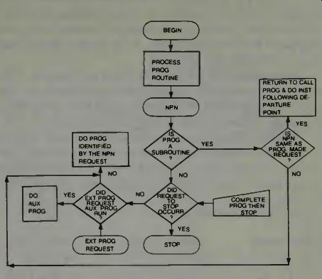
Fig. 6. A Flowchart for the Versatran robot Executive Program (courtesy
Prab Versatran). One subroutine calling from another subroutine is referred
to as "nesting". Nested subroutines form a chain of subroutines which
are linked to the original calling program.
If the second subroutine calls for another subroutine prior to returning to the first subroutine, the chain, or "nesting", grows. Up to twenty (20) levels of subroutines can be nested in this manner.
The return to the original calling program, from where the first subroutine was called, is accomplished in the reverse order in which they were called.
NESTED SUB-ROUTINES: MAIN PROGRAM #1 BEGIN ; PGN. . .1: 1; TDL. .10: 2 ; ILD. 100: 3 ; CSR. . .2: 4 ; NPN. . .1: SUBROUTINE #2 SUBROUTINE #3 BEGIN ; PGN.. .2: 1; TDL. .20: 2 ; ILD. 100: 3 ; CSR. . .3: 4 ; NPN. . .2: BEGIN ; PGN. . .3: 1 ; TDL. . .5; 2; ILD. 100: 3 ; NPN. . .3:
The main program calls for subroutine #2 at instruction sequence 3. Similarly, subroutine #2 calls for subroutine #3 at its third instruction sequence prior to returning to the main program. Therefore, subroutine #3 is nested to the main program through subroutine #2.
Once subroutine #3 has completed its program, it re turns to subroutine #2 at instructions sequence 4. Consequently, subroutine #2 returns to the main program at instruction sequence 4 and the process is repeated.
Twenty (20) levels can be nested in this manner prior to any one subroutine returning to its calling program. Sub routines which are not nested can be repeated indefinitely, as long as they return to their calling program prior to being executed again.
UNNESTED SUBROUTINES: MAIN PROGRAM BEGIN ; PGN. . .1: 1 ; TDL. .10: 2 ; ILD .100; 3 ; CSR. . .2: 4 ; CSR.. .3: 5 ; NPN. . .1: SUBROUTINE #2 SUBROUTINE #3 BEGIN ; PGN.. .2: 1; TDL. .20: 2 ; ILD .100: 3 ; NPN. . .2: BEGIN ; PGN. .3: 1; TDL. . .5: 2 ; ILD .100: 3 ; NPN.. .3:
The main program calls for subroutine #2 at instruction sequence 3. Once subroutine #2 completes its program, it returns to the main program at instruction sequence 4. At that time, subroutine #3 is called (from the main program) and executed. When its program is finished, subroutine #3 re turns directly to the main program at instruction sequence 5.
Once a CALL SUBROUTINE instruction is encountered, all further movement of the robot arm is relative to the position of the arm at the time of the instruction: i.e., the Control Unit considers the position of the arm where the departure occurred as the HOME POSITION (position 1) of the sub routine.
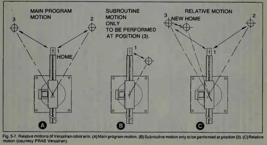
Fig. 7
The samples as shown in Fig. 7a and 7b are showing the motions of the robot arm for the main program and the subroutine program respectively.
If a CALL SUBROUTINE instruction occurs while the robot arm is at position 3 of the main program, that position becomes the HOME POSITION or position 1 of the sub routine. All motion of the robot arm in the subroutine is therefore relative to position 3 in the main program (see Fig. 7c). Upon returning from the subroutine to the main pro gram, the next instruction following the CSR instruction of the main program will be executed. It is therefore advisable that the last position called for in the subroutine is the same position as the starting position of the subroutines in order to resume the program with the robot arm in the position it was when the departure occurred.
EXAMPLE 7: Call Subroutine (CSR. .XX) (a) Purpose: To OPERATE THE MAIN PROGRAM with a CALL SUBROUTINE instruction occurring at position 3.
(b) Detail: MAIN PROGRAM Identify the program number used.
STEP 1: INITIALIZE VELOCITY STEP 2: INITIALIZE RATE STEP 3: START AT HOME & GO TO POS 2 STEP 4: GO HOME STEP 5: GO TO POS 3 STEP 6: DO SUBROUTINE 12 STEP 7: GO HOME STEP 8: REPEAT THE PROCESS SUBROUTINE Identify the program number used.
STEP 1: INITIALIZE VELOCITY STEP 2: INITIALIZE RATE STEP 3: START AT HOME & GO TO POS 2 STEP 4: GO HOME STEP 5: REPEAT THE PROCESS (c) Source Program: MAIN PROGRAM Sequence Function Instruction No. Command / Value Enter Code BEGIN; Prog Number 7 (.;PGN...7:) 1; SET VEL 6 (1;SVL. . .6:) 2; SET ACC /DEC 6 (2;SA/D...6:) 3; CALL POS 2 (3;CPN...2:) 4; CALL POS 1 (4;CPN...1:) 5; CALL POS 3 (5;CPN...3:) 6; CALL SUBROUTINE 12 (6;CSR...12:) 7; CALL POS 1 (7;CPN...1:) 8; Next Prog Number 7 (8;NPN...7:) SUBROUTINE BEGIN; Prog Number 12 (.;PGN..12:) 1; SET VEL 10 (1;SVL. .10:) 2; SET ACC /DEC 10 (2;SA/D. .10:) 3; CALL POS 2 (3;CPN.. .2:) 4; CALL POS 1 (4;CPN...1:) 5; Next Prog Number 12 (5;NPN..12:) (d) Teach: ( i) Mode Select key to the TEACH position.
( ii) ENTER both Source Program starting with BEGIN. (iii) SET and RECORD positions 1 (HOME), and 2 on the subroutine program.
(e) Check: ( i) Mode Select key to the SINGLE STEP position.
( ii) Press the SINGLE STEP FWD Control to review each instruction in sequence.
CAUTION: It is recommended that the JOG switch pushbutton is operated each time it lights since the subroutine arm motions are RELATIVE TO THE POINT OF DEPARTURE. In this way avoiding obstructions or pegging the arm against a mechanical stop can be assured.
(f) Operate the Program: ( i) Mode Select key to the AUTO RUN position.
( ii) Press JOG to move the Robot Arm HOME (position 1). (iii) Press the RUN PROGRAM switch button to execute the program.
Skip Sequence Number Instruction (SKIP. .XX). The SKIP SEQUENCE NUMBER instruction is a conditional jump which bypasses the next instruction in the program sequence when the condition of the specified input line is "true." When the SKIP Function Command is encountered, the Control Unit will check the condition of the line specified by the function value (1-32). If the line is "true," the next instruction in the programming sequence is skipped, consequently, the one following the skipped instruction will be executed.
However, if the specified input line is "not true" the next instruction will not be skipped.
EXAMPLE 8: Skip Sequence Number (Instruction Code SKIP. .XX) (a) Purpose: To move the robot arm from target A to target B avoiding any obstacle and check target B for a part. If part is in position pick-up and move to target A; if part is not in position do subroutine UNTIL PART IS IN POSITION, THEN REPEAT THE PROCESS. (b) Detail: Identify the program number to be used.
STEP 1: INITIALIZE VELOCITY STEP 2: INITIALIZE RATE STEP 3: START AT HOME AND GO TO TARGET A STEP 4: RELEASE THE PART STEP 5: GO HOME STEP 6: GO TO TARGET B STEP 7: CHECK FOR PART; : YES BACK: STEP 8: DO SUBROUTINE STEP 9: CHECK FOR PART: YES 1 YES: STEP 10: GO BACK TO 8: BACK STEP 11: GO TO TARGET B STEP 12: PICK UP PART STEP 13: GO HOME STEP 14: REPEAT THE PROCESS NOTE: Upon return from a subroutine, the next instruction following the CALL SUBROUTINE is executed. The pro gram desires to repeat the subroutine if the part is not at target B. Therefore after returning from the subroutine call the next instruction is to check for the part again, if it is not there an immediate jump back to step 8 (Do subroutine) instruction is executed. An immediate skip instruction is coded by a Function Command SKIP SEQ NUMBER and a function value of 1000 plus the program sequence number desired. (Hence STEP 10 of the source program, SKIP 1008:) (c) Source Program: Sequence Function No. Command Value Enter Instruction Code BEGIN PROG NUMBER 8 (.:PGN...8:) 1 SET VEL 6 (1;SVL. . .6:) 2 SET ACC /DEC 6 (2;SAD ...6:) 3 CALL POS 2 (3;CPN...2:) 4 OUTPUT CMD OFF 1 (4;000F...1:) 5 CALL POS 1 (5;CPN...1:) 6 CALL POS 3 (6;CPN...3:) 7 SKIP SEC) NUMBER 2 (7;SKIP...2:) 8 CALL SUBROUTINE 12 (8;CSR..12:) 9 SKIP SOO NUMBER 2 (9;SKIP...2:) 10 SKIP SEC) NUMBER 1008 (10:SKIP 1008:) 11 CALL POS 3 (11;CPN. . .3:) 12 OUTPUT CMD ON 1 (12;OCON...1:) 13 CALL POS 1 (13;CPN...1:) 14 NEXT PROG NUMBER 8 (14;NPN...8:) NOTE: The Source Program of example 8 assumes that the part pickup device is connected to output line 1 and the part position device is connected to input line 2.
NOTE: Program sequence number 11 recalls position 3 to be sure that returning from the subroutine places the arm over the part pickup target.
EXAMPLE 9: Program To Use All Instructions Used In Examples 1 Through 8 (a) Purpose: To get part at target A and move to target B when part is "ready". If part is not ready, go to target C and spray target area with short burst. Check for part ready, if not continue spray.
Note: The program of example 9 assumes: Part pick-up Device on line 1.
Part Position Sensor on line 2.
Spray gun actuator in line 3.
HOME IS POSITION 1 FOR BOTH THE MAIN PROGRAM AND THE SUBROUTINE. TARGET A IS POSITION 2 OF THE MAIN PROGRAM AND TARGET B IS POSITION 3 OF THE MAIN PROGRAM. Fig. 8. Versatran robot's arm motion when waiting for a part (courtesy PRAB Versatran).
----------- Versatran). INSTRUCTION Main Program 9 DETAIL
Table 2. Function Command Value Meaning.
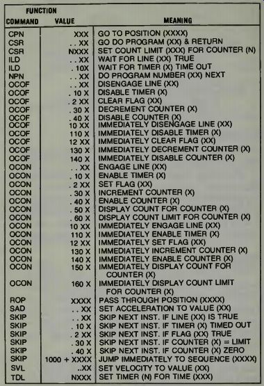

List of Instruction Codes Each instruction code is made up of two (2) parts; the function command and the function value.
Function Command. The function command is a general description of a task to be done, see Table 2.
Function Value. The function value is a specific description of what action should take place. An instruction code is used by the Control Unit to produce a definite action. The following is a list of instruction codes and their meaning.
Review Controls
The review controls are used to inspect each program sequence instruction contained in memory. The SINGLE STEP FWD and SINGLE STEP REVERSE Controls provide a means of executing one instruction at a time or beginning the program from a sequence other than the first instruction.
In this way, the operator can review and inspect the operation of the program.
Single Step Forward. Once a program number has been selected and the mode select switch is placed in the SINGLE STEP position, pressing the SINGLE STEP FWD Control executes the first instruction in the program sequence. At this time, the program teach panel indicators will display the Program Number, Program Sequence, Function Command, Function Value, and the Position Number. When a new position is called, the JOG switch lamp will light. Pressing the JOG switch button will allow the robot arm to move towards the position being displayed by the position number.
NOTE: It is recommended that the JOG switch button is operated for each position when a new program is first entered to the Control Units memory. In this way, the operator is assured that the robot arm has a free path to travel. If the operator is sure the robot arm can reach the position being called for without striking any objects the RUN PROGRAM switch button can be pressed to move the robot arm to the new position at program speeds.
CAUTION: Once the RUN PROGRAM switch is pressed in the single stop mode, the robot arm will move directly to the position. Releasing the RUN PROGRAM switch button will not stop the motion of the arm. If under these conditions the arm is about to strike an object, the EMERGENCY STOP Control should be engaged.
Single Step Reverse. The Single Step Reverse Control is used to start a program from an instruction sequence other than sequence one. This may be desirable in the event an Emergency Shut down was required or power failure occurred, while the program was partially through its cycle.
Starting the program from the sequence where the "stop" occurred to complete the operation that was in process, can be conducted as outlined in the following procedure.
Procedure: (i) Place the Mode Select key in the SINGLE STEP position.
( ii) Operate the SINGLE STEP FWD Control until the de sired program sequence number appears in the Program Sequence display.
(iii) Press the SINGLE STEP REVERSE Control.
( iv) Press the CONTROLLED STOP (yellow mushroom switch) on the Operator Panel.
( v) Press and hold the JOG switch until the robot arm is in the appropriate position.
( iv) Press the RUN PROGRAM Switch on the Operator Control Panel to execute the program beginning with the instruction sequence displayed in the Program Sequence Indicator.
NOTE: It is recommended that the COMPLETE PROGRAM THEN STOP Control is activated once the program begins operating in this mode. Once the program stops, the Mode Select key should then be placed in the AUTO RUN position the JOG switch pressed and held until the robot arm is in position 1; and the RUN PROGRAM switch activated to execute the program in the normal mode of operation. Editing Controls These controls are used to alter or change the program or instruction sequence when corrections are necessary.
They consist of the INSERT and DELETE Controls.
Insert. The Insert Control is used to place an instruction in the program sequence. When the instruction is inserted at a specified program sequence number, the instruction originally at that program sequence number becomes the next instruction following the inserted instruction.
Procedure: (i) Mode Select key to the TEACH position.
( ii) Press PROG SEQ NUMBER and the desired program sequence number on the keyboard: ENTER number.
(iii) Prepare the desired instruction code (function command and function value) to be inserted.
( iv) Press INSERT. Delete. The Delete Control is used to take out the instruction specified by the program sequence number selection. When an instruction is deleted, all following instructions move up one number in the program reference to avoid gaps in the program. In this way, the next instruction, following the instruction deleted, will be executed in the program sequence where the deleted instruction had been originally.
Procedure: (i) Mode Select key to the TEACH position.
( ii) Press PROG SEQ NUMBER and the desired program sequence number on the keyboard: ENTER the number.
(iii) Press DELETE. With the use of Editing Control, the program can be modified without having to change the sequence number of all instructions.
Simple Programs/Problems
The following provides three (3) examples of programs which use many of the instruction codes contained in the Instruction Code List (Section E). Each program provides a description of the task and an explanation of the program.
Following the examples are three sample problems which can be used as an exercise for the reader. A solution to these problems can be found at the end of the section. How ever, other solutions are possible and the reader is urged to use imagination and ingenuity in solving the problem.
EXAMPLE 1:
(a) Task: To start at Home and move the robot arm to location A. At location A, set the horizontal arm into a stroking motion (back and forth) and repeat the stroke five times. Then move the robot arm to location B passing through Home and repeat the stroking motions of the horizontal arm at location B, return the robot arm to Home and repeat the process.
(b) This program calls for the same routine to be done at both locations A and B. The stroking motion of the horizontal arm can be put into a subroutine motion of the main program. Since subroutine motion of the robot arm is relative to the position of the arm at the point of departure from the main program, the positions A and B will become position 1 of the subroutine. It is further necessary to keep track of the number of strokes in the sub routine, since the task limits the number to five.
(c) Source Program and Detail:
-----
Main Program
Program sequence 1 clears the counter (SET TO ZERO) and establishes a limit of 5 counts. Sequence 2 and 3 provide the single stroke motion. Sequence 4 adds one to the counter.
Sequence 5 asks if the counter has reached a count of 5. If it has not, the next instruction (sequence 6) returns to sequence number 2 where the stroke and count are again executed. If five strokes have been counted program sequence 5 requires that sequence 6 is skipped, consequently sequence 7 instructs a return to the main program to the next instruction following CSR XXXX: instruction.
(departure point)
EXAMPLE 2: (a) Task: Start at Home and go pick up parts at location A and move them to location B for a 5 second test. If the part tests good, move to location C and dump the part, if the part tests bad, move to location D and dump the part.
Furthermore, if after 10 parts, two or more are bad, stop the process and sound an alarm. If less than two are bad, test 10 more parts.
NOTE: This program will assume the part pick up device is on line 1. The external TEST source is on line 2. A good parts sends a TRUE signal on line 2, and the alarm is on line 3.
(b) Source Program:
EXAMPLE 10.3: (a) Task: To get part at location A and move part to location B. At location b, give part a two minute bath with rotary motion; after two minutes, move to location C and dump part. Repeat the process.
NOTE: This process calls for an extended time interval beyond the 99.9 second limit of a timer. Consequently, set ting a timer for one minute and executing the instruction twice will accomplish the desired task.
The program will assume the part pick up device is on line 1 and the part rotate device is on line 2.
(b) Source Program: Thus we conclude this study of how an industrial robot, the Prab Versatran may be programmed and controlled and taught. Other types of industrial robots will have a similar concept of operation. It is not difficult to program such a robot and the tasks may be varied a great deal from the illustrations used herein. Also, it is possible to use one computer to control many robots on an assembly line, or to integrate the actions of many robots to accomplish whatever jobs are desired.