AMAZON multi-meters discounts AMAZON oscilloscope discounts
We assume that a robot has at least one arm which can move, and that the robot can turn to any desired azimuth to perform the task which we have programmed into it. In the types of industrial robots we have considered so far, one arm per machine has seemed to be standard. Of course we are considering that a second arm, not attached to the robot itself, but controlled by the same master controller and synchronized with the movement of the main arm is a distinct possibility. However, in this section, we will deal with the "hand" or manipulator of just a single arm.
COMPARISON TO THE HUMAN ARM AND HAND
Because humans tend to think in terms of what they can do with their own appendages, they tend to design robots so that they duplicate humans. Somehow, in the back of our minds, we are thinking, "If we can do it, then a robot built like us can do it." So, we want the robot to be such a machine that it actually tends to duplicate our own movements with regard to the upper torso. As far as mobility is concerned, that doesn't seem to be much of a consideration except for the fact that the robot must be able to traverse the type and kind of terrain in which it will operate if movement is required. It is not necessary that a robot have legs and ankles and feet, nor that it have just two of these if it is actually necessary that it duplicate the humanoid from the waist down, mobility-wise.
In some cases where the terrain is rugged or mountainous more appendages have been considered and a spider-like bottom half is what the designers came up with. This, of course, would be especially necessary if the terrain is such that one cannot go around obstacles, but has to climb over them.
AMAZON multi-meters discounts AMAZON oscilloscope discounts
The robot must duplicate the human upper torso if the tasks assigned are such that it is doing work which a human formerly performed, and thus the rest of the work environment is geared to humans. Programming becomes easier because one can plan the movements and operations by comparing the robot's movements to those of a human who is very good at that job. Of course, one might take the viewpoint that a robot should be designed so that it is a unique device and doesn't duplicate the human.
We want to consider some of the similarities and differences between a robot and the human appendage. First let us consider the shoulder. In the simplest case the robot's shoulder joint would permit an up and down movement of the rest of the arm. To get the azimuth movement the human enjoys, the robot's body is turned in a circle. The result is very close to a human arm when the human is lying on their side. The human arm can describe a circle using the shoulder joint alone as the pivotal center.
The robot is capable, without stress on design, of an arm movement from the shoulder joint, which a human is not capable of; that is the extension or retraction of the upper arm elements. This permits the robot's arm to reach further and work closer than a human might be able to. Where a human might have to take a few steps to reach something, then step back to get close to the work area, the robot, by means of the extension capability, can remain in a fixed position and do the same task. The elimination of the mobility requirement here might be a decided plus for the robot in that it cannot get out of line, has fewer moving parts to worry about, and is simplified in design and cost. It is more cost-effective, in this manner.
Now we consider the elbow joint. It could be important that this joint have a dual capability, or triple capability. It should permit the forearm to lengthen and contract, it should permit up and down motion, and it should permit a rotary motion so that the "up and down" movement can be at any angle.
The robot, to have maximum manipulator movement, needs maximum flexibility of arm movement. If a robot is designed in such a way that it is to accomplish tasks which are not envisioned at the time of design, then a maximum capability of design has a better chance or permitting the robot to do these unforeseen or unimagined tasks later in time. Of course one realizes that for a specific task the robot under consideration may not have to have as much arm movement or flexibility of appendage as we are now considering. Less flexibility may mean less down time and certainly less cost. Thus one encounters, again, the concept of cost effectiveness of a robot doing one or two or a few tasks versus the completely flexible robot.
The wrist of the robot certainly needs a rotary capability, and an up and down capability. It probably does not need the extension capability of the other two arm elements. The wrist of the robot is where the gripper will be attached, and that device is what will enable the robot to do useful work. To do useful work the robot must have the right tool in the right place at the right time and manipulate that tool in the right manner for the required time to accomplish the task.
The human wrist has a good movement up and down and a somewhat limited movement sideways, but it can also be rotated, when considering the play of bones and muscles from the elbow joint down to the hand. If you examine your own hand's movement you'll find that the wrist rotates about 180 degrees only, but the hand can be rotated this much when bent down or up, or even, to some extent, when it is bent sideways.
It is not the elbow which permits the rotary movement of the wrist, but the forearm bones and muscles, and the elbow doesn't cause any arm rotation at all, but we might want this in a robot. It is easier to design the joint which has both translator movement and angular movement, then to try to exactly duplicate the bone structure of the human forearm. Remember, what we will be looking for in the final design, is movement of a hand or gripper through those necessary points in space required for accomplishment of whatever task we have assigned to that robot.
Finally, we come to the hand or gripper. Now we need to make some slight distinction. If we call the end appendage a hand then we want to consider that it has some kind of fingers or graspers in an amount of three or more, one of which might be considered a thumb or opposing lever. The gripper on the other hand might just be considered to be a pincers arrangement of two fingers, which close on an object to a pre determined force level, and permit the arm to raise or move the object so grasped.
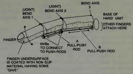
Fig. 1. Making a metal finger close and open using push rods.
The appendage attached to the wrist of an industrial robot may be some tool such as a drive socket device to fasten down bolts, or a drill, or a welding torch, or whatever. A good robot may be able to use one tool on a task, then move its arm so that that tool can be discarded or disengaged. The arm then moves to the location of another tool, moves the wrist so that the second tool is fastened in place on the wrist, and then the arm moves to perform tasks with the new tool. In this case there are no fingers or grippers as such. There is just the end tool which is positioned by the robot so that it can do the kind of work it was intended for.
A side note here to those of you who thought that fingers on a robot would be comparable to fingers on a human.
Although possible, such a thing is probably not very useful.
Take a look at Fig. 1. As you see, in this sketch, there are three finger sections shown which represent the end joint, the second joint, and the first joint of a finger. If we provide some small nubs at each joint we can exert a lever force on the finger element causing that part of the finger to move up or down as we would push or pull some flexible push-pull rods as shown. Such rods are ideally worked by small hydraulic pistons like the model airplane type used for landing gear extension and retraction. As some force is necessary, and the lever advantage is relatively small, the hand would not have a strong grip.
If we imagine such a finger grasping something, we would imagine that push-rod B is pulled back moving the second finger element down, then push-rod A is pulled back causing the finger end element to come down and so we have a kind of grasping action. The push rods would have to be flexible enough to withstand the bending, or a two way cable arrangement might have to be used on each nub to get up and down movement of the finger element. Mechanical engineers love a problem like this and delight in imagining just how to design the mechanism to do the job as shown. But even if such an appendage is useful, it is doubtful if it is cost effective, so we leave it to your imagination.
SOME SCHEMATIC
When studying mechanical robots which have many moving parts it is sometimes useful to diagram those elements which move in a simplified manner. If you are so inclined, and talented enough, you can write some equations of motion which describe the moving elements. We examine this type of robotic symbolism in Fig. 2.
In section A we see a representation of an inward outward type of movement such as might be gained from the use of a hydraulic or pneumatic piston. If we want to show that a robot's arm extends and contracts, schematically, we might use this symbol.
In section B we show rotation about a vertical axis. This movement can be called a one degree of freedom, even though we can readily see that the axle and pivot arrangement will permit the mass to rotate in either direction about that vertical axis. Perhaps then, we can define degree of freedom as a movement about or along a single axis. If we have a robot arm with five degrees of freedom, we would expect the sections of the arm to have at least five hinge joints, or thrust joints such as at A or B. In C of Fig. 2 we see an arrangement which describes two degrees of freedom. Notice that the mass (M) can move around a horizontal axis or a vertical axis or both. In D we show a schematic of a free gyroscope which has three degrees of freedom. If we want to use our schematic representation to show this configuration, we do so as at E. When the kinematic or dynamic situation of a robot's arm is being considered, it is nice to use such diagrams, adding one to another so that the entire picture may be obtained. The mass as shown does not represent the load which the arm may be moving, it can represent the inertia of the arm itself. That is a considerable problem in dynamics because the inertia of the arm changes with each position it assumes, with respect to most pivotal joints. This makes the equations of motion difficult to write and to solve! Most robot arms currently have under six degrees of freedom. But, as an exercise let us examine an arm with 12 degrees of freedom, in Fig. 3. As a sure cure for insomnia one might imagine writing the equations of this arm, recalling that each degree of freedom involves a second order differential equation. Then imagine a method of simultaneously solving all the equations! If sleep doesn't come soon, consider the changes in inertia previously mentioned and some types of other non-linear relationships which have to exist in such an arrangement.
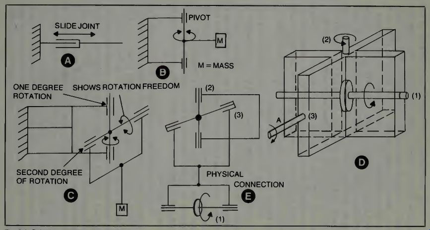
Fig. 2. Robotic symbolism for schematics.
It has been pointed out that the determination of the required number of degrees of freedom of any robot arm will be governed by the application of that robot and the conditions under which it must operate. Recall how the Prab robot overcame an obstacle in its arm trajectory? If we consider a robot doing a painting job inside a car body, in order to paint the interior thoroughly, getting the arm through a body opening and bending the hand around to spray the interior, might indeed require more than a few degrees of freedom. A General Motors painting robot has sensory capability to detect a car body entering its world, spray it carefully, and using a second hand open the door so the painting arm can get through to spray the interior! Coordination of the arms and hands is, of course, computer controlled. This robot uses both magnetic and optical sensors in its operation.
From what we have considered with respect to the arm of a robot, we now have a clear concept of the two things that happen. First the arm moves the end device into the required position in three dimensional space. Then the end device is actuated by signals from one or more sensors. When it has completed its task-determined by other sensors-it moves back to the starting position. Meantime the arm may have changed its spatial orientation as a function of time or its program sensing progress detectors, so that an entire job may be accomplished.
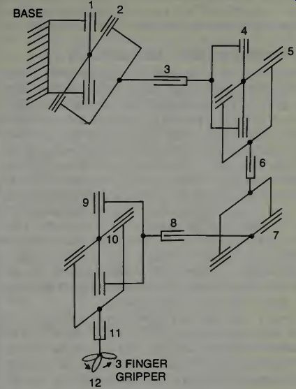
Fig. 3. A robot arm with 12 degrees of freedom.
We need to mention two other types of end devices. The first is the sucker, which can hold onto various parts simply by creating a suction or vacuum. Normally those parts held would be rather light weight parts, although lots of suckers can produce a formidable attractive and holding force. We also need to mention the magnetic holding power to electromagnetic elements in hands or grippers. These exert considerable force which can easily be turned off and on by means of electric switching. They are not useful when handling non-magnetic type parts or when the parts are apt to have a high degree of residual magnetism, however.
Limit switches, which can be made an integral part of a hand are also very useful in that they can provide a feedback signal when the closing pressure has reached a given magnitude. These type sensors would be mounted inside the hand in such a way that when the hand clamps an object, pressure would cause the switch to close and thus create a signal that a given force had been exerted by the jaws. The system might be so programmed that once such a switch has closed, the controller would automatically cause a continued closing of some very, very small amount. A sensor tells the computer there is contact with the object, and the computer, knowing the flexibility of the object, orders a slightly tighter closing so that the object might be lifted without falling from the hand or slipping into a disoriented position in the hand. It could be that several microswitches each requiring a slightly higher force to close, might be used to sense the gripping forces applied.
EXAMINATION OF A ROBOT'S ARM KINEMATICS
There are many possible orientations of the various joints in an arm which can permit the end device to reach the same given spatial coordinate. The selection of any given version of a kinematic plan for a robot's arm is determined by many specific conditions and requirements. One consideration is that the arm must have a sufficient degree of movement to do everything required in its work cycle. Second, from the engineers viewpoint, the movements must involve the greatest simplicity of design of the arm and its elements, and thus keep the unit cost effective. When the end device is so moved, it must have the proper angular orientation at that point to do the type job required of it. When these two factors alone are considered it has been found that, in general, it requires at least six degrees of freedom of motion. This does not include those motions of the end device itself which may have several degrees of motion freedom.
Some robots need only three degrees of freedom to do the job which they were designed for; i.e., a vertical motion, a horizontal motion and one rotational motion. In this case there would not be a translatory motion in and out of the arm.
If the degrees of freedom were increased to 4 then this translatory movement might be incorporated. If the end device must have a certain number of degrees of freedom, the arm must make up the number of degrees of freedom which the end device does not produce or have in itself.
Since, we know that the number of degrees of freedom can represent various kinematic plans for the arm. The de signer can lay-out the kinematics of the arm to satisfy such requirements as he may deem necessary for that particular application of that particular robot. Of course, he may over design the arm for some installations and realize that the arm will just meet the requirements for another installation, but this gives the arm more use in a wider spread of applications, even though it becomes less cost effective for the smaller application.
When a designer considers the arm itself and its kinematics he will want to consider several factors. One of these is that the change in the angular orientation of the end device when it is at some specified point in its work zone, must not involve significant movements of the arm elements which are located some distance away from the end device. One brings this down to an earthy level by saying that when a human wants to grasp a pencil, he moves his fingers, not his shoulder muscles. The designer considers the distribution of the necessary number of degrees of freedom when the total number of freedom degrees is a constant. If the cost effectiveness requires that you can have only four degrees of freedom, where should they be located? So we find that in order to maintain the necessary maneuverability of a robot's arm seven to nine or more degrees of freedom might be required on some tasks. You don't have to play around with mathematic or proofs to show this, just layout the work area and draw the kinematics required for the tasks.
POWERING THE ROBOT'S ARMS
General Motors expects to use about 14,000 industrial robots in their factories by 1990. As many of the parts and tools used in automobile production are quite heavy, we need to further examine a robot system with regard to how the arm is powered.
At each joint, or section of the machine, there must be powering units to control the movements and position of the extensions appended thereto. We might even conclude that a robotic arm consists of many individually controlled elements, each with its own set of operating signals and sensors, which become integrated into one unit under the control of a master computer, or programmed drum, or both. The drive devices, which we are at the moment interested in, are placed in various ways to control the motion of the arm. Most generally they are placed directly at the joints or on the elements of the arm near a joint. But because you don't get much leverage, this is suitable only when the arm is not required to lift heavy loads. We must also consider that type of drive where the powering units are all located near the shoulder joint and use other means of transmission of power from the drive sections to the elements of the arm. In some applications this may be a good way to power the elements so that the weight of the drive units are not on the arm itself, and thus the weight lifting capability vs the weight of the arm ratio might be increased. Finally, we must consider the third alter native, which is that there be a combination of element-drives and remote-drives for the operating machinery.
The three types of drives used are the electric, the hydraulic, and the pneumatic. Each has some particular ad vantages when used in robotics applications. The pneumatic and hydraulic systems require pumps at some remote location, with only the hoses going to the machine. Control can only be precise using sensors, however, load capability is excellent. Electric motors are another matter.
The electric motors are easily powered and may be designed for low inertia. Thus they are capable of excellent acceleration, de-acceleration, and velocity control, but they are heavy for the amount of horsepower produced. They have excellent reliability records. In the past there have been some machine operations using electric motors working at constant speeds, using various types of speed reduction units, which may be controlled electronically, and also using clutches to transmit the power from the drive unit to the various elements. Clutches can engage and disengage quickly and have, in the past, offered quite high reliability in such applications. It is possible that for certain robotic applications in the future, some systems or even parts of systems, may use clutches and electric motors as a part of their powering system.
Without clutches it is necessary to use stepping motors in robots. Robot manipulators using these powering devices are capable of very discrete and tight control and such motors work easily with digital type input signals. If the stepping movement is large, then some auxiliary type equipment needs to be used, on the grippers to turn this step movement into a smooth precise movement of the end device.
Finally, we should not overlook the use of such items as a powered selsyn type of transmission and powering system for certain robotic applications. These may have either a physical or electrical input and can be very precisely controlled even though their physical power output is very low. They might be used in conjunction with other types of powering units and so give the smoothness and precision and power required for many applications.
THE PLANET ROBOT "ARMAX"
In Fig. 4 we see a one arm robot made by the Planet Corp. of Farmington Hills, Michigan. The grippers may be replaced with other tools as required. This unit uses hydraulic power and the source of that hydraulic power is usually remotely located from the unit. This robot is designed to be used in welding, material handling, machine loading/ unload, gaging, deburring, flame cutting, surface finishing, and spray painting operations. Figure 5 shows its world. In this illustration we can see the vertical and horizontal profiles of its work area.
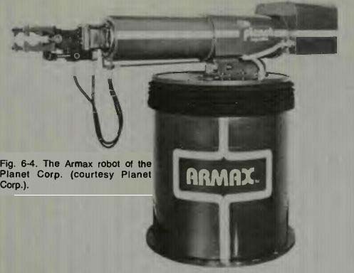
Fig. 4
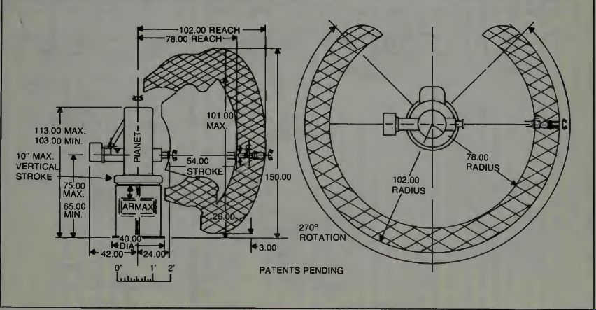
Fig. 5. The World of Armax, the robot.
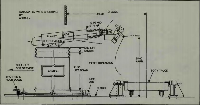
Fig. 6. Armax robot operates a wire brushing wheel (courtesy Planet Corp.).
In Fig. 6 we see how the robot is used to manipulate a wire brush over an automobile body. The brush must come down on the body at a given point and with a given pressure.
Then it must move precisely over a pre-planned curve, which might be a welded seam, for example, and then at the end of its movement, it needs to lift off the body and wait until another body slips into position. The machine must be taught just how to move its brush, of course, and a computer will memorize that information.
Planet Corporation says their robots may come in two variations; a servo controlled robot or a programmed robot.
The servo-controlled type is operated by a computer which has one section for each controlled axis of movement. It uses a high level language and incorporates some adaptive control so it can adjust to changes in its external environment. This robot is taught with a hand held unit similar to the ones we have previously described.
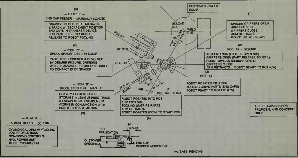
Fig. 7. Armax does parts handling. Its method of operation (courtesy Planet
Corp.).
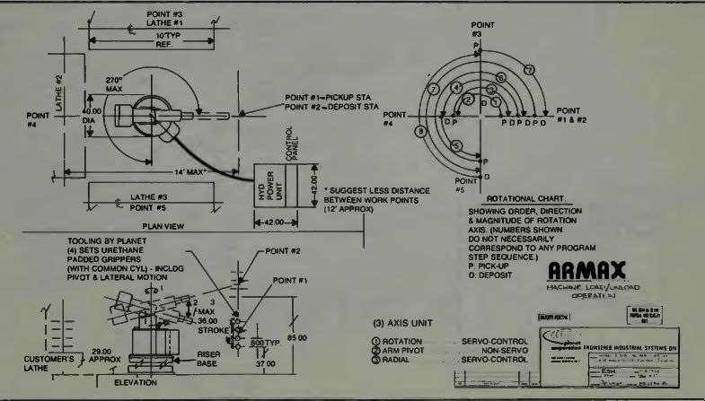
Fig. 8. Armax loading/unloading capability
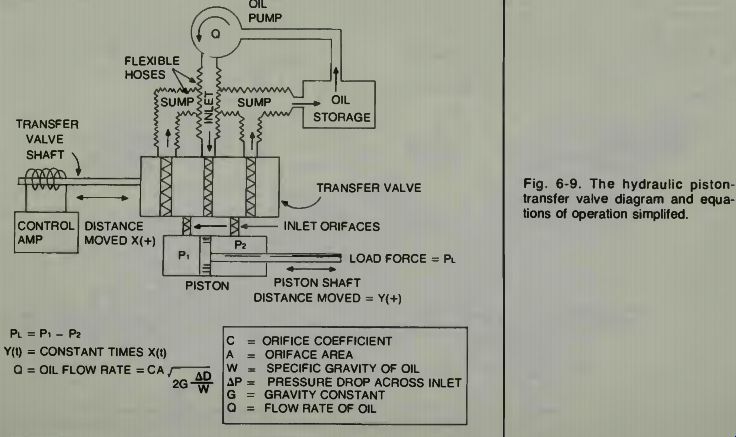
Fig. 9
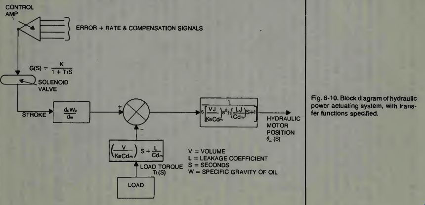
Fig. 10
In Fig. 7 the layout of the Armax robot is shown and its operation is indicated for a parts handling job. This job consists of handling a part which must be deburred and then placed in a different location. This is a programmed robot.
That means that its actions are controlled by pegs in a drum which close various switches causing the various operations to be performed. We look at note 1. The spacer grippers open, the arm extends the grippers close and the arm retracts with the item and turns clockwise. In position 2 the arm extends, the machine opens up, the grippers open and release the part to the machine. The arm holds still while the de-burring procedure takes place, then the gripper closes and the arm retracts again and the robot arm is ready to rotate clockwise.
In 3 the robot arm rotates into the position indicated and some tooling grips the part and the robot arm is ready to rotate clockwise. In 4 the robot arm rotates into the position shown, the arm extends and the tooling ungrips the parts. Now the arm retracts and the arm rotates counterclockwise to start at position 1 again. Notice that a gravity feed is used on the parts, and also that the parts are fed by a mechanical escapement which is operated as the arm rotates. This is necessary because control is not accurate enough to pick up and precisely orient small parts with a hydraulic robot.
Figure 8 illustrates the positions the arm takes when it is used in a machine load/unloading operation. Notice the legend which uses a letter P for pick-up, and the letter D for deposit of the part at the point indicated by the numbered arrow. Now, let us take a look at hydraulic drive and control.
THE HYDRAULIC DRIVE SYSTEM FOR ROBOT ARMS
The basic piston-transfer-valve drive for a hydraulic system is well known and the equations are easily derived when considering the flow rate, dimensions of the piston and valve, coefficients of friction, orfice flow, and the mass and load acceleration requirements. The basic unit and equations in a simplified form are shown in Fig. 9. In this diagram we see that the total force exerted by the piston will be equal to the differential pressure (p1 - p2) and that this pressure will, in turn be governed by the flow rate of oil through the transfer valve into the piston. We note that the rate-of-change of the piston shaft position (y) turns out to be some constant times the transfer valve shaft displacement (x). A little more elaborate diagram which shows the control amplifier with its many inputs, the solenoid, and a load reaction. The expected transfer force minus the load reaction equals the actual transfer of power. The arm position sensor feeds information back to the control amp.
Finally, we show in Fig. 11 a very simplified diagram which can be used to develop the second order differential equation of motion for the hydraulic piston, valve, and load.
We realize that nature tries to balance the forces rep resented. The piston force tries to make the load accelerate and move. The mass of the load and the friction in the load system or robot arm system or whatever, tend to resist motion. There must be a force greater than the retarding forces if the system output is to be moved, and there is to be an acceleration of the load. The load might be the members of the robot's arm system, or might be the arm plus whatever the arm is lifting or moving. In any event we want the arm and load to move smoothly and accurately without vibration, oscillation, overshoot, or other minor problems.
In a hydraulic system the forces can be considerable since the force exerted on the piston shaft will be a product of the pressure of the oil times the area of the piston. Assume a 300 lbs/sq. in. pressure and a piston area of 6 square inches.
The shaft pressure can be 1,800 lbs.
The favorable aspects of a hydraulic system are low weight per-unit-power, low inertia of output member, high speed of operation, and large force development. Some of the limitations include the requirement for the auxiliary power system, possible leakage problems, and minimal control.
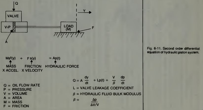
Fig. 11
THE PNEUMATIC POWERING SYSTEM
This system using air as the working fluid is probably the fastest type system possible to obtain. Inertia is low, as with the hydraulic system, and the air may be vented into the atmosphere, which eliminates the need for a return flow system. Air is obtained from the atmosphere and compressed into pressurized tanks.
In pneumatic systems one uses air under pressure to operate pistons, and also one may use the suction. This may be used to provide power to suckers which might be placed on grippers to hold certain types of packages or objects, or to attract them into the gripper jaws.
Although air is light weight and easily available, it poses some problems in that any contaminants in the system, even moisture, can cause trouble with system parts such as valves and tightly sealed pistons. But when its application fits a particular need, then it is used to quite a large advantage. On letter sorting machines used by the Post Office an arm moves to a stack of letters, grips one by its face with suction, moves it to another position by rotation of the arm, and then releases it with a short explosion of air.
OTHER METHODS OF POWERING ROBOTIC ARMS
The use of action envelopes with robotic drives has been studied by some. These are said to be quite sensitive and can range from low-powering to quite high powering-devices.
They consist of tubes and bellows and follow the traditional action of these type elements.
You have a tube into which you can force non-compressible liquid such as hydraulic systems use. The tube does not lengthen, but tends to expand sideways and contract lengthwise, just as human muscles do. Thus a pulling action is available just as with a human muscle. When the pressure is released, the tube lengthens again and the sides return back to a normal diameter. No moving piston is necessary in this case. One attaches the load to the end of the tube and can pull it or, by use of a second tube and proper dynamics, push it to whatever position one desires.
Gripper Module spring-actuated / parallel gripping motion (external); fitted with workpiece-adapted jaw inserts
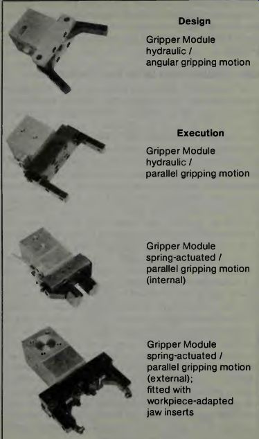
Fig. 12. FIBRO-MANTA gripper units for robotics (courtesy Fibro-Manta).
Regardless of how the arm is powered, robots all use the same kinds of grippers and in Fig. 12 we show some developed by FIBRO-MANTA. They too are powered by electric motors, hydraulics, and pneumatics. The grippers may be caused to operate by proximity detection or by program. The use of springs gives a snap action which might be necessary when high speed of operation is required. For handling certain types and shapes of work pieces, special inserts may be placed inside the jaws which then conform to the required dimensions to insure a tight grip on the piece of work being handled.
SOME CONSIDERATIONS OF THE PROGRAMMED ROBOT
There exist in our world a large number of machines which have been called robots. Many find this terminology not at all acceptable for these kinds of machines. As stated by Dr. James S. Albus of the National Bureau of Standards, "Most of these mechanisms exhibit few of the characteristics the average person would associate with the term robot; they are mostly pick-and-place machines that are capable of only the simplest kinds of motions. They have little or no ability to sense conditions in their own environment. When they are switched on, they simply execute a pre-programmed sequence of operations. The limits of motion for each joint of the machine are fixed by mechanical stops, and each detail of movement must be guided by means of an electric or pneumatic impulse originating at a plug-board control panel.
In a typical application, each row of the plug-board represents one degree of freedom in a specified robot joint, and each column represents one program step. Connections are made in appropriate rows and columns to determine which joints are actuated, and in which direction, at each step.
Whenever a new program is needed, the mechanical stops can be re-positioned and the programming connections can be relocated to set up a new series of movements. A more sophisticated level of control can be achieved by adding servo mechanisms that can command the position of each degree of freedom to assume any value. The addition of servo-control requires feedback from sensors such as potentiometers en coders and resolvers, which measure the position of each joint. The measured position is then compared to the commanded position, and any differences are corrected by signals sent to the appropriate joint actuators.
This excerpt is interesting because it tells us how, in general, a programmed system operates. A robot's arm may be moved by command signals which originate either from a timing and sequence drum which closes switches at various times, or from a computer which draws upon its memory for the movement commands. The difference is that the computer may have solved some equations as part of its own intelligent operation, it directly commands the movements and speed of the arm, and it analyzes the feedback to make adjustments. The program drum-which was set and patterned by us-could only move the arm one way, at one speed to get to its final position.
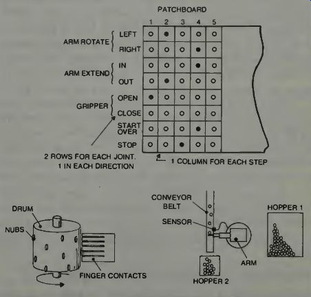
Fig. 13. A- sketch of an imaginary "patchboard panel" which might
program a robot.
THE PATCHBOARD PROGRAMMED ROBOT
It really is a pretty dumb kind of machine. Let us examine Fig. 13. Please realize that this is just an example to illustrate our points. You can probably easily imagine a much better and more complete programming unit for a real-life job. Plugs go into the patchboard where the dark dots are. As a rotary switch makes contact with the plugs at each step, the corresponding joints are activated. The actions are stopped by mechanical stops or sensors attached directly to the arm.
This board will open the grippers, dropping an item into hopper 1, then pull in its arm as it rotates to the left.
Positioned over the conveyor, it waits to close the gripper until the sensor is triggered. Notice this is not done by the patchboard. The sensor could sense light, or color, or, using magnetism, metal composition. The result is that items not tripping the sensor go into hopper 2. When the sensor is triggered, the grippers close and the rotary switch starts again, proceeding to step 4 where the arm moves out and right, over the 1st hopper. The START OVER plug indicates to the rotary switch (not the arm) to disengage and swing around to position 1, where it all starts again.
In some types of robotic machines a rotating drum is positioned at a starting point and around its circumference are such holes as we have shown and switch actuating pegs are placed in these holes. When the whole unit is placed into operation the drum starts rotating and closing and opening switches according to the various peg positions. The speed of the rotary switch or drum controls the period of time between steps, but the speed of movement cannot be controlled.
Although it may seem that this type machine is not useful, that is not true. It is simple and reliable and will perform its operations, even rather complex ones, with the same precision and accuracy time and time again. You know how useful and reliable the washing machine, dryer, and dishwasher are in your home? This kind of machine is that type. For some industrial operations this type machine may be much more useful and cost-effective than the servo controlled machine. We will probably see everything from pencil sharpeners to lawn mowers called robots in the future years.
SERVO-MECHANISM DEFINITIONS AND CONSIDERATIONS
The world of electro-mechanical control states that servo-systems fall into two general categories: the open loop system and the closed loop system. It is common to find the following definitions used with regard to these systems: open loop system-A system of operation where the input does not depend on the output.
Closed loop system--A system of operation where the input does depend on the output.
Examine Fig. 14. In Fig. 14A we see a typical open loop system which has no feedback. The output is expressed simply as the product of the various transfer functions of the various blocks of the system, as illustrated. These functions are usually expressed in Laplace Transforms.
Systems such as this open loop system can be used for control purposes assuming that we know where the arm is currently located, or that the arm is always returned to home or starting position at the end of each programmed operation or cycle. The input could be a series of polarized digital pulses sent from a computer that remembers where the arm is and where it needs to go next. The polarized pulse would turn a stepper motor the proper direction and distance. Assume that we have one such servo-system for each element of the arm. This means that if we have the shoulder section, the forearm and the wrist, that we would have three such servos in operation.
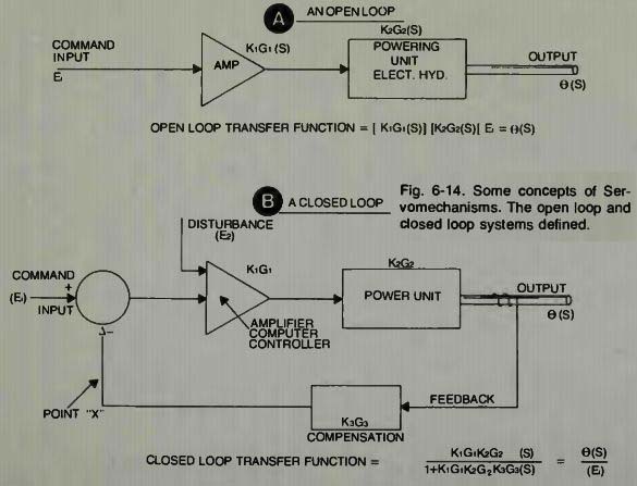
Fig. 14
Our three servos might operate in this manner. The first servo will move the whole arm-it being the shoulder servo.
Once the whole arm has been moved, then movement is relinquished to the forearm servo for more precise positioning of the wrist and gripper, or hand, and finally, the wrist is positioned so that the torch, paint gun, or whatever is in the desired position for task performance.
If we know the exact end-position that the hand has to reach, we can provide the correct number and type of digital pulses, as a function of time, to make the robot's arm move to where we want it to move. This concept of programming would work with the drum or patchboard too, if the servos have distances pre-set. Notice that no feedback is required.
The whole machine simply gets an input of pre-arranged and polarized digital pulses which it amplifies and sends to various stepping motors at a proper time so they will operate correctly and without mutual interference. This machine can also do useful work, accomplishing jobs suited into this sort of mindless type operation. The advantages of this type system are simplicity and low cost, because no feedback is needed, and a higher degree of accuracy than hydraulics are capable of.
In connection with the programmed movement of the arm of this type robot, there might be external mechanical switches operated by the arm as it passes. In this manner, bins might be opened as the arm swings toward them. Parts would then be fed into a belt. The combination of operating pulses of an electronic nature and the genius of mechanical engineers combine to make a machine do almost wondrous tasks! It seems there is a place for the open loop type control system in actual industrial applications.
Why, then, do we want a closed loop system? Using feedback and some internal computing element, it is capable of adaptive control. Only a closed system can adapt to varying situations.
It is interesting to note how the control equations of such a system are derived. One simply takes the product of all error detectors and then writes this group of terms as a fraction. Consider the loop opened at point X in Fig. 14. We can derive the open loop type transfer function to use in the formulation of the closed loop equation as shown. Realize, of course, that the KG terms can be very long and complicated expressions using the Laplace Transforms. Any good text on Servomechanisms will illustrate how this is done.
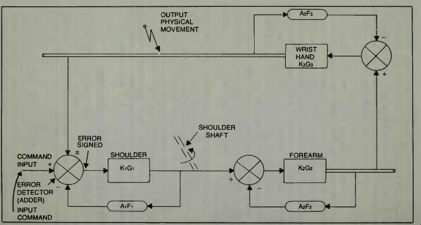
Fig. 15. The concept of series servos in a robotic system.
SERIES AND PARALLEL SERVOMECHANISMS
A system of series servomechanisms which might be used to control the arm of a robot is shown in Fig. 15.
Assume that there is a command input from some place in the system. This causes the shoulder servo to activate, moving its output element physically until it is as close as it can get and the command is zeroed out. At the same time that it moves, it causes a command signal to the forearm element so that it also moves just as soon as the input command signal is large enough to cause the second servo system to operate. It, too, will move until the command signal is reduced below some operating threshold value-when the error is so small the servo sees no signal. Finally, the third servo is activated in a like manner and it moves until its input command is reduced below threshold value. In this movement, just to insure overall stability of the series arrangement, a feedback is made from the final output element to the primary input error detector, and this signal may be positive or negative as required for accuracy and stability.
Notice that we have a feedback around each servo for its own stability and precise operation, and that there will be an over-all loop from the output back to the input. Thus we have loops inside of loops! Techniques for writing the equations of such a system are well known. Computers can solve such equations and will permit playing around with variables, so one might have an interesting time seeing just what would happen in this situation, with and without load, with varying amounts of inertia, and if one considers some velocity and acceleration response situation requirements.
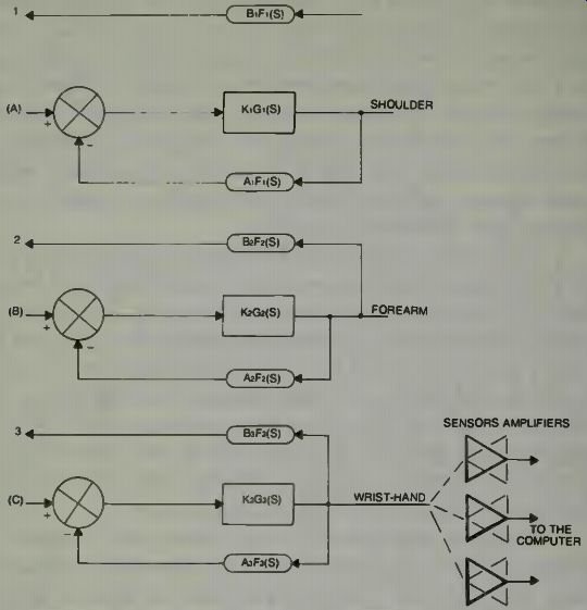
Fig. 16. Using parallel servos to control a robot's arm.
The input command, which may come from a computer, will govern the actual movement. The inter-relationship and inter-dependence of one arm element on its preceding element means that either the computer will have to do the calculations, or there will have to be pre-set servos, summing amps, or some other form of controlled feedback.
Parallel arrangement of servo systems can move the arm elements either together or sequentially as necessary.
This situation might be diagrammed as shown in Fig. 16.
Here we see how a servo system controls the movement of the shoulder element. This servo has its normal feedback for stability and compensation, and it also provides feedback (1)to the computer driver which generates the input signal (A). Thus the shoulder element can move such that its end point (the elbow) will position itself at some coordinate as commanded by the input. The computer will know this and be cause of the feedback, will know just how the element is moving in space to get to that point. Meantime the computer can direct the second servo to move the forearm at the same time and along some pre-computed trajectory, and it can keep track of what is happening with this second element even as it programs and commands the first element. The same thing happens to the hand. Sensors on the hand will tell the computer that the hand is on the object, has grasped it, or that the hand is now ready for some further signals.
Just one further point concerning servomechanisms of this type. We have mentioned the threshold signal level. The smaller the signal which can make the servo operate, the smaller the actual error in position, velocity, or acceleration will be, however it is also more susceptible to noise.
ROBOT HANDS AND HUMAN HANDS
A study was made of the technical feasibility of constructing a robot hand which would be like a human hand. It was found that the human hand is just too complex for such duplication in the first place, and in the second place, it really isn't necessary to exactly and completely duplicate the human hand to have that robot perform well enough to replace humans at some tasks.
Some of the interesting facets of this study were that the human hand has some fifteen joints which result in some twenty two individual degrees of freedom. Think about writing equations to describe such movements! Although this number of degrees of freedom might be required for playing a piano, who wants a robot to play such an instrument? If you can't play it yourself, you can buy a player piano or record player.
The study showed that of the technically realizable manipulations possible for a hand and fingers, a hand having only one finger can perform about 5 percent of all the manipulations needed. If two movable finger parts are used (a gripper) then the totality of possible manipulations is increased to about 40 percent. If a third freely moving finger is added, with the same number of degrees of freedom as the human hand, then almost 90 percent of the possible technical manipulations can be performed. Adding a fourth finger increases the manipulative ability to some 99 percent. There isn't much use going beyond this capability.
If a two finger hand is our familiar gripper, the three fingered hand would be one in which fingers would be mounted on a wrist at 120-degree spacing, as in Fig. 1. If one were to design a hand with an additional rotary joint incorporated at the base of each finger, so that each finger could be rotated with respect to the others, and still maintain their gripping power and capability, then some 75 percent of all the manipulations of a human hand might be accomplished.
One "ideal" hand has four joints per finger, for three of the fingers, and the bases of these fingers are separated more than they are on the human hand. Three of the joints are controlled in whatever manner is most suitable, the fourth joint is automatically controlled by the second joint. The wide base arrangement permits the "thumb" to fold out of the working area between the other fingers. With this device some 89 percent of human hand operations might be achieved. In a human hand the joints use sliding surfaces which, in part, are deformed during the motion of the joint. Also the human hand has very complicated gliding joints which are continuously lubricated with the joint fluid and have an exceptional safety system which prevents joint damage. The safety system consists of force and pressure sensors. The manipulating force per finger of the human hand is somewhere around 3.5 to 5 kg and is about 25 kg for all fingers working as a unit. It would be difficult to duplicate this variable capability by machine. With the pincers or gripper type hand one can design for large forces, up to 10 times the force of the human hand, and this type design has become very practical. The mechanical hand can operate at a faster velocity and acceleration than the human hand, and does not tire when moving at a fast pace. Also the wear on the mechanical parts is very small even when doing a fast task and exerting considerable forces in the task.
The mechanical hand may, or may not have environmental sensors. Infrared beams of light, generated within the grip of a mechanical hand could permit the hand to sense the proximity of objects it is trying to pick up. The human hand has many more sensors. It has a cold and hot sensor, feel sensors, pressure sensors, and force measurement sensors which are an integral part of the human hand's construction. If we include heat and cold sensors in a robot's hand, these might generate alarm signals if things begin to get too hot or too cold. Force measurement sensors are currently available in a number of different configurations, from limit switches and variable magnetic-signal transformers to piezo crystals.
There are several hundred thousand receptors distributed over the human hand. Considering this, it is immediately obvious that we can never build an artificial hand that duplicates the human hand precisely! One hand has fingers which each have 12 degrees of freedom. The hand could give a rough idea of its surroundings by detecting corners, and determining structure symmetries, and so on without seeing the objects. The sensor signals were sufficient for a computer to build the image.
When humans solve a grasping problem, they are only conscious of the final process which is to feel the object. They are no longer conscious of the individual motions which lead to the final result. This is all programmed by means of a lengthy learning process. Small children learn to grasp objects with their hands and do this at various distances from their bodies. They learn how to manipulate their hands and arms and wrists for round, thin, long, short, and fat objects.
When this learning phase is over, they have a fixed program in their nervous systems or in their brains for the control of the various motion elements which make possible the manipulations required, and in such a manner that certain motion chains will automatically occur in a fixed sequence or desired sequence, and in synchronization with other parts of the human system.
The total robotic manipulation process is first decomposed into signals in a first, upper level. These signals deter mine which elements should be activated. The individual motion elements themselves are then activated in a second logical process. The final manipulation is produced by means of an additional synchronization control system governed by the adjustment of the pressure forces and the manipulation of these forces among the various body elements. The organization of such subordinate functions are autonomous, but influence each other in an adaptive control system manner. This is called hierarchically organized information processing. Much of the "feedback" information in robots is accomplished with analog circuits whose signals are then digitized for computer processing as we know.
CLOSED-LOOP SERVOSYSTEMS AND FEEDBACK
We have again mentioned feedback in connection with a closed loop type of servo-system. We shall see in later pages how a velocity feedback is important to the overall stability of one type of industrial robot. Let us examine the concept of feedback further in preparation for the information yet to come.
We can diagram a rather complex multiloop servo-system as shown in Fig. 17. There are three feedback loops shown, two of which have some kind of compensation amplifiers in their lines. The feedback to the input is, of course, the output shaft or element's position.
We define a transfer function as the ratio between output and input. The abbreviation for the transfer function is T.F. as shown in the illustration.
By being able to write a mathematical expression which tells us what happens to the voltages, currents, or physical elements controlled by the blocks, using the inputs and feed backs as shown, we are able to examine how the output responds to changes in loading, gain of various blocks, the addition of various rates of change in voltage or current.
Signals representing the velocity or acceleration of physical elements will affect the output, whether these signals develop in the feedback loops or in the forward part of the loop or block input line.
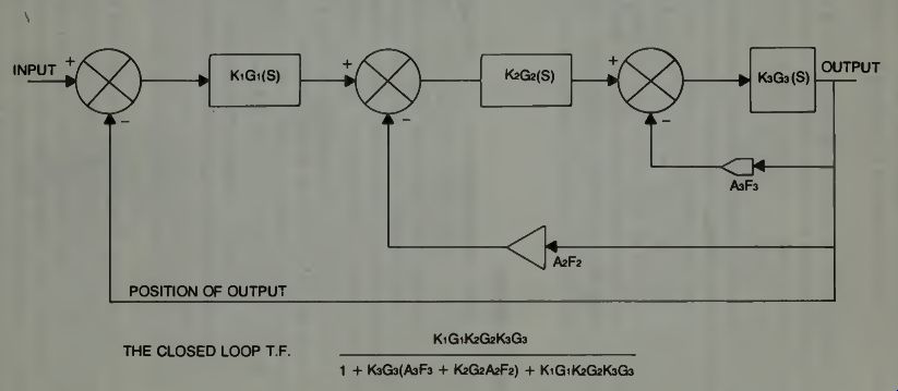
Fig. 17. A multiloop servo system suitable for robotics applications.
Because the computer will show the effects of these variations and also show whether to increase the torques or power applied, or increase the damping-which prevents oscillation-one can design a whole industrial robot system on paper and try it out on a computer before anyone has to spend a dollar buying expensive motors and gears and such, to make the thing, and try it out experimentally. Of course the final proof of design is always the building of a model and making such adjustments to it and corrections to its control as are necessary to make it do exactly what it is intended to do efficiently and precisely, and, hopefully, economically.
If we look at a general second order differential equation in the form:
Jp2 x + Fpx + Kx = C or (Inertia x Acceleration) + (Friction x Velocity) + Power = C,
... where C is the command input. Then, if we know that the addition of a type of control such as velocity feedback will affect the second term or the damping term of the system, we can predict what will happen if we add this control to the system. Also, if we use a proper acceleration type feedback, we can predict whether this will have the effect of increasing or decreasing the system inertia.
We can vary the value of the system power term (K) and see what happens. In a general way, we can add anything to the block diagram, write its transfer function, mathematically manipulate the equation till we get it in the form shown and then look at it, and put it in a computer for solution and see what we have done! Sometimes that is amazing and surprising! If our system tends to hunt or oscillate about a final position then we might have to increase the friction or damping term of the system to effect a cure. We might do this by as simple a technique as adjusting a potentiometer. If we find the robot arm moves too slowly into a final position, so that a part goes by before the arm grippers can grasp it, then we might adjust the K term-also by adjusting a potentiometer-and correct the delay. We might find we have to adjust many potentiometers or controls all at the same time for a particular installation to make the robot work exactly as it should in that application. There can, and will be, in the normal course of events, many feedbacks in a robotics system and all these are necessary.
ELIMINATING THE ERROR
A closed loop servo system operates on an error signal.
The open loop systems operate on a command input signal.
The closed loop systems always compare the output to the input and the difference between them is the error signal, it seems we always must have an error signal for the system to operate. We have discussed some problems associated with trying to minimize that error. It is possible to eliminate the operating error if one uses integral control methods! What this kind of control does, in effect, is to average up the amount of signal developed in an error and then, through its block of control, develop a voltage proportional to that error and of the proper polarity to cause the motor controller of the robotics system to eliminate the error entirely! A very simplified block diagram of such a system is illustrated in Fig. 17.
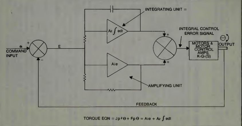
Fig. 18. An integral-control servosystem may be used in robotic applications.
Here we see the integration amplifier in the forward loop of the system. It is possible to obtain this effect with a proper compensation in the feedback loop also, but we do not obtain complete elimination of the error so easily. In effect we make the system very sensitive and so it can easily become unstable if there is no other compensation used to damp out any oscillatory tendencies. When everything is finely adjusted so it does operate as it should, there will be no error in output but if there is any slight change to voltages in the system it might throw the balance off and cause some problems. Integral control is a delicate type of servomechanism, but it exists.
--------------
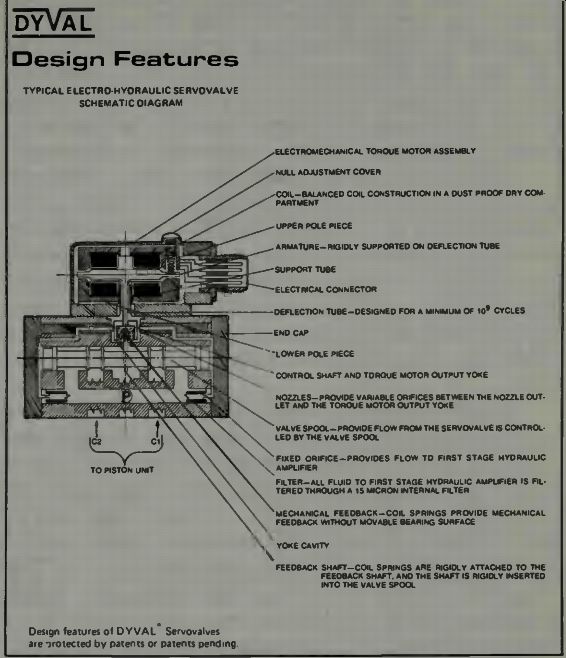
Fig. 19. Electrohydraulic servo-valve-schematic diagram (courtesy Dynamic
Valve Co.).
Design Features
TYPICAL ELECTRO-HYDRAULIC SERVOVALVE SCHEMATIC DIAGRAM
C2 C1 TO PISTON UNIT Design features of DYVAL" Servo-valves are protected by patents or patents pending ELECTROMECHANICAL TOROUE MOTOR ASSEMBLY NULL ADJUSTMENT COVER COIL-BALANCED COIL CONSTRUCTION INA DUST PROOF DRY com. PARTMENT UPPER POLE PIECE ARMATURE-RIGIDLY SUPPORTED ON DEFLECTION TUBE SUPPORT TUBE ELECTRICAL CONNECTOR
DEFLECTION TUBE-DESIGNED FORA MINIMUM Of 109 CYCLES ENO CAP
Lower POLE PIECE-CONTROL SHAFT AND TORQUE MOTOR OUTPUT YOKE NOZZLES-PROVIDE VARIABLE ORIFICES BETWEEN THE NOZZLE OUT LET THE TORQUE MOTOR OUTPUT YOKE VALVE SPOOL-PROVIDE FLOW FROM THE SERVOVALVE IS CONTROL LED BY THE VALVE SPOOL FIXED ORIFICE-PROVIDES FLOW TO FIRST STAGE HYDRAULIC AMPLIFIER FILTER-DLL FLUID TO FIRST STAGE HYDRAULIC AMPLIFIER IS FIL. TEBEO THROUGH A IS MICRON INTERNAL FILTER MECHANICAL FEEDBACK-COIL SPRINGS PROVIDE MECHANICAL FEEDBACK WITHOUT MOVABLE BEARING SURFACE YOKE CAVITY FEEDBACK SHAFT-COIL SPRINGS ARE RIGIDLY ATTACHED TO THE FEEDBACK SHAFT. AND THE SHAFT IS RIGIDLY INSERTED INTO THE VALVE SPOOL
------------------
DETAILS OF ELECTROHYDRAULIC SERVOSYSTEM
Some robots are constructed with a combination of electrically operated transfer valves and either hydraulic or pneumatic pistons controlling the arm movements. Examine a cut-away of an actual hydraulic transfer valve. Notice that the valve is operated by torque motors. Figure 19 shows the cut-away illustration.
Locate the valve spool. This is the element which is moved by the torque motor to permit oil to flow to a piston, not shown here. This valve controls the input to one side of the piston while at the same time permitting the exhaust of oil from the opposite side of the piston back to a sump of some type. In order to have a quick response to the electrical signals, it is customary to have the spool dither, which simply means it vibrates in accord with a low amplitude, high frequency signal imposed on the control winding of the torque motor along with the control signals. Realize that it is easier to keep something in motion than to start it in motion, so this action is used to keep the valve spool moving and thus pre vent delays due to sticking deadband. Deadband is that region of no response where a change in the control signal will not cause a corresponding pressure change of the piston.
Some other terms used to describe phases of operation of a transfer valve are: null-the condition where the servovalve supplies zero control flow at balanced load forces across the piston.
Null shift--the condition which results from a change in the bias current which produces a null. The shift is expressed in terms of a percent of the rated current of the servovalve.
Deadband--that region of no response where a control signal will not cause a corresponding pressure change in the piston.
Linearity--the degree to which the normal flow curve con forms to the normal flow gain line with the other operational variables held constant. It is measured as the maximum deviation of the normal flow curve from the normal flow gain line and is expressed as a percent of rated current.
Threshold--the increment required to change from an in creasing output to a decreasing output.
Since we have mentioned curves, let us examine the curve of normal input and output control tolerance for the type of servovalve under discussion. Look at Fig. 19.
Notice the tolerance lines, dotted on each side of the solid reference line. By taking the span between the tolerance lines, in the vertical direction (y axis), one can obtain the increment by which a percentage of the load flow may be calculated. The illustration shows a 10 percent rated flow.
Also a projection on the X axis will give the percent of rated current. Both English and Metric units can be used to de scribe flow and other important dimensions as illustrated.
Finally, we want to examine two actual, commercial servodriver units from Dynamic Valve Co. These are the electronic parts of a servosystem which operate the servovalve previously shown. In Fig. 21A we see a schematic for a velocity servodriver, and we note that it has an integral control element in the forward gain loop. There is a control there called the integrator sensitivity control and this can be adjusted to obtain the desired effect on the servo performance.
If we consider for a moment the effect of an error in a servosystem in which velocity of movement is important, and is an input specified quantity, we will realize that an error in this quantity will cause the wrong velocity, or an oscillation about some normal desired value. We don't want such an error in this type of system. We want it to get to the desired and commanded velocity and hold that velocity. The integral-control type of servo can make this possible. Notice in that same system that a tachometer is used for derivative feedback compensation. This produces the stability required.
Sometimes it is desirable to be able to open the loop of a closed loop servosystem in order to check signals at various points and in some cases to locate troubles. In a closed loop system, where the system always tries to minimize its error, one might have a lot of trouble trying to see what kinds of signals are actually being produced by the various blocks of the system. When we open the loop we can create a static condition which permits us to see what these signals are, since there is no way the system can function to reduce the error as we have previously defined the error signal. In block A of Fig. 21 we see the switch which opens the loop for testing or adjustment or whatever.
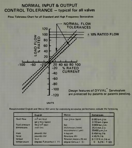
Fig. 20. Servovalve curve showing characteristics of its operation (courtesy
Dynamic Valve Co.). NORMAL INPUT & OUTPUT CONTROL TOLERANCE - typical for
all valves Flow Tolerance Chart for all Standard and High Frequency Servo-valves
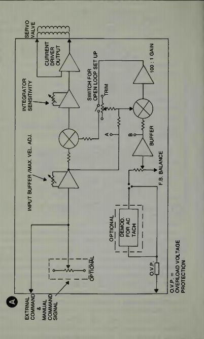
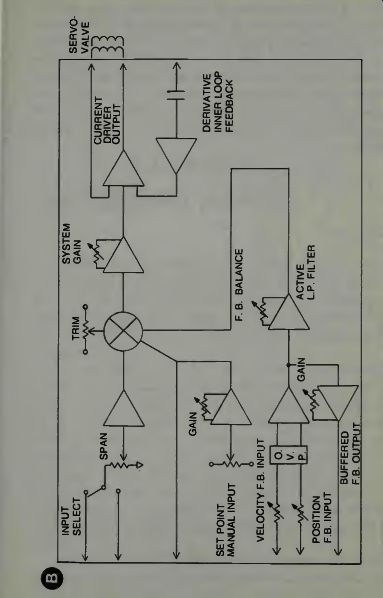
Fig. 21. Servo Driver unit electronics schematic (A) An integral control
velocity driver amplifier. (B) A positioning servodriver amplifier.
In block B of Fig. 20 we examine a positioning type of system. There is a control to adjust the value of the gain (K), and there is compensation, with derivative feedback of an electronic type. In a way it is like the tachometer feedback, but doesn't operate from the moving output element as the tachometer type does. This type operates from the signal and is able to determine changes in the signal and the rate of change of the command or error signal. There is also a velocity feedback to the input and various other controls for balance and monitoring purposes. In all cases the output of the servodriver units is sent to the torque motor on the hydraulic transfer-valve which, in turn, controls the output piston producing the power and movement required of the system.
We should not conclude this section without mentioning that Dyval, Inc. also makes a transfer valve which has a pneumatic element mounted on the hydraulic valve, and this pneumatic element controls the hydraulic flow. In systems where air pressure is used to control fluid flow, the system has a combination of both power and speed. Recall that a pneumatic system is said to be the fastest mechanical system because the air can be moved faster than oil, however, air is compressible and so for power, without elasticity, one needs the non-compressible hydraulic fluid as the power producing element.