AMAZON multi-meters discounts AMAZON oscilloscope discounts
The robotic arm described in the following pages, courtesy of Microbot and Robotics Age magazine is one which its inventors say can be used for hobby purposes, for research purposes in computer program development, or just for robotics experimentation. The arm is operated by a computer as illustrated in Fig. 1.
In the operation shown, the arm is being directed to pick-up and stack some small wooden blocks in a sequential order. This is not a professional application, but is fun, as is the writing of the computer program to accomplish such tasks. You can see the relative size of the arm. You might remember GARCAN and wonder if such an arm might not be attached to that paraplegic robot. One advantage of this unit's size is that you can develop various computer languages and programs for robotic use, and then check these programs without having to resort to the expense of procuring a full size robot.
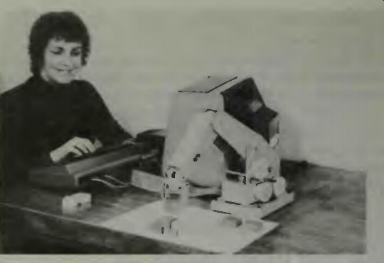
Fig. 1. Computer operation of the hobby-research robot arm is easy (courtesy
Microbot).
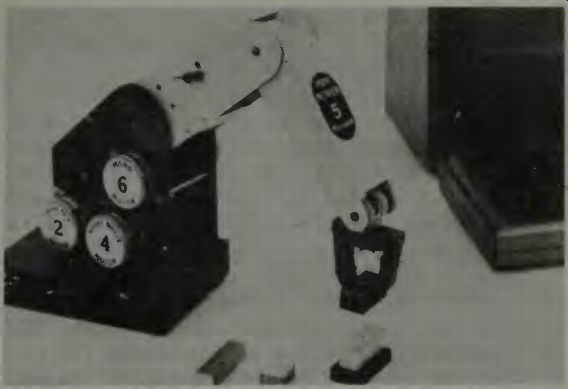
Fig. 2. A close view of the Mini-Mover 5, as the arm is called, and three
of the six motors used in its operation. Motors 1, 3, and 5 are on the opposite
side of the arm in this view (courtesy Microbot).
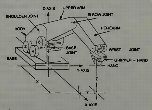
Fig. 3. The coordinate system for the robotic arm (courtesy Robotics Age).
Many universities and research centers are now developing the necessary communication languages for robot control and programming, using computerized programs which-are of great complexity, yet plan their own manipulation strategies, efficiently performing complex coordinate transformation mathematics. Studies are being made to use more and better sensors and get better use from the available types of sensors, and studies are being constantly made to gain a better understanding of the robot's kinematics. The Mini-Mover 5 as this robot arm has been named, was de signed to assist this kind of research.
AMAZON multi-meters discounts AMAZON oscilloscope discounts
LOOKING AT THE ARM DESIGN AND OPERATION
In Fig. 2 we see a close-up of the Mini-Mover 5 with its gripper and three of its 6 stepping motors. These control the arm and gripper movement. The motors are; base drive, shoulder drive, elbow drive, 2 for wrist drive, and the gripper.
In the upper right hand corner of the illustration we can see a portion of the computer used to control this unit.
Because a coordinate system must be designated for the arm and the gripper-and this is true for any robot system-we show in Fig. 3 how this is designated for the Mini-Mover 5. You will notice that a rectangular system of coordinates is used which has its origin at that point where the base of the arm pivots on a supporting surface. The gripper, then, will be displaced from the origin in some X, Y coordinate direction, and have an altitude position in the Z direction. One might wonder if using a system of polar coordinates wouldn't identify the gripper position much easier? Remember that the arm will be responding to a series of pulses which, in turn, will step the various stepping motors.
Thus it might be easier to program the unit to move five units right (X) and two units out (Y) and drop the gripper itself down two units (Z) to engage some object.
We note that this arm's gripper has five degrees of freedom because it is driven by a differential gear mechanism which can rotate the gripper in both pitch and roll. Add this to the motions of the body, shoulder, elbow, and wrist and you have a sufficient number of degrees of freedom so that the arm can be accurately positioned and the gripper positioned in a partial sphere whose radius is 17.5 inches from the origin.
We have mentioned earlier in this guide that in some cases of robot design, one might use motors which drive various elements through the use of cables or linkages. That is the case with this robot arm, as shown in Fig. 4.
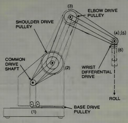
Fig. 4. The cable diagram for the Mini-Mover 5 robotic arm (courtesy Robotics
Age).
The drive motor for each joint consists of a stepping motor, reduction gearing, and a cable drum. From each drum a tensioned cable goes out over pulleys to the member being driven and then may or may not return to the drum. Rotation of this drum causes rotation of each member in proportion to the diameter of the drive pulley attached to that member and the drum's diameter. The movement of one joint on this arm may result, therefore, in the motion of another joint, and this may not be desirable. Here is how the designers of the Mini-Mover 5 describe the cabling operation, which must be understood if you are going to compensate for these unwanted movements by properly programming the operation of the arm:
"Base Rotation (Joint 1)--The base drive cable passes over two idler pulleys, making a 90 degree bend, to a drive pulley fixed to the base. The base drive motor causes the entire arm to rotate about the base joint.
"Shoulder Bend (Joint 2) --The shoulder drive cable passes around the drive pulley on the upper arm segment to rotate it about the shoulder joint.
"Elbow Bend (Joint 3)--The elbow drive cable passes around an idler pulley on the shoulder axis to a drive pulley fixed to the lower arm segment. Joints 2 and 3 interact, so that changing the shoulder angle results in an equal change in the elbow angle. This interaction has been designed so that the elbow drive, in effect, controls the angle of the forearm with respect to the horizontal. However, the limits of forearm motion are measured with respect to the upper arm, not the horizontal (x-y) plane.
"Wrist (Joint 4, left and Joint 5 right)-The fourth and fifth drive cables pass around idler pulleys on both the shoulder and elbow joints and terminate on the drive pulleys of the left and right wrist differential gears. The interaction of these joints with joints 2 and 3 has the effect that the wrist drives control the angle of the hand with respect to the horizontal (pitch) and the rotation of the hand around its pointing vector (roll). Through the action of the differential, the pitch angle P equals the average of the positions of the left and right gears and the roll angle R is their difference. The range of motion is limited to ±270 degrees at each of the wrist gears due to limits of the cable length and to ± 90 degrees in pitch due to interference from the lower arm.
"Hand (Joint 6)--The hand drive cable passes over idler pulleys located on the shoulder and elbow joints, through the center of the wrist differential, and finally terminates at the hand. This drive interacts with joint 3 (elbow) in that elbow bend will cause the hand to open slightly. This can be compensated for by closing the hand exactly the same number of steps that the elbow is raised." Examine a view of the hand and its differential gearing in Fig. 5. It is interesting to examine how the grippers have been made for this robot. Each section is like a two-section finger, and in the finger tip portion are surfaces which permit gripping an object so it won't slide away.
SOME NOTES ON THE GRIPPER OPERATION
Another diagram of the cabling arrangement for the grip per is shown in Fig. 7. Notice the torsion spring which permits the hand to open when the cable tension slackens.
Also notice the switch which could prevent a too-tight grip and thus causes cable breakage. This also has a second function, which is to cause the cable to tighten slightly more after it first grasps an object. This switch sends a signal to the computer that an object has been grasped and so, if desired, one might program the computer so that when it gets this signal, it can cause another step or so of the tension motor so that a good tight grip results.
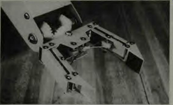
Fig. 5. The Mini-Mover 5 hand (courtesy of Microbot).
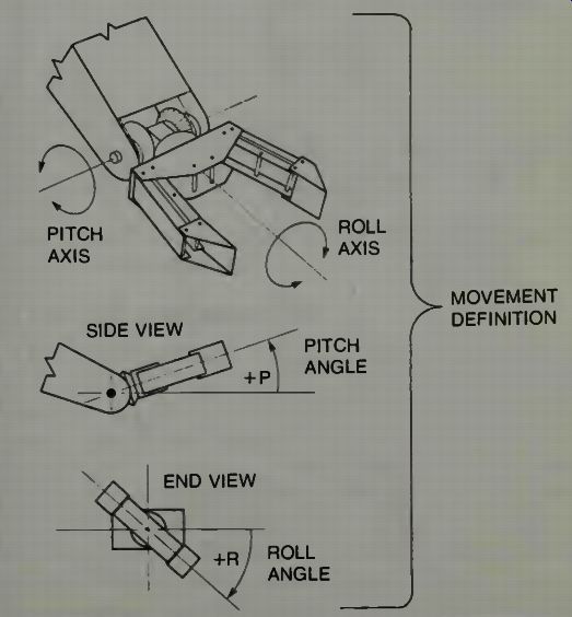
Fig. 6. Mini-Mover 5 hand gearing and cable arrangement to grippers (courtesy
Microbot).
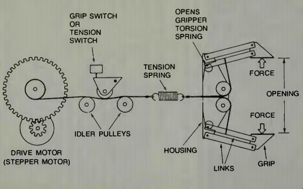
Fig. 7. The cable diagram for the gripper operation (courtesy Robotics Age).
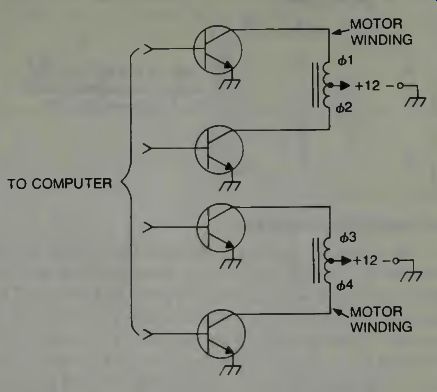
Fig. 8. The transistor drivers for two stepper motors. Since each arm element
has a "forward and reverse" direction, when you step one motor, you
must also step the other to permit movement (courtesy Microbot).
OPERATING THE STEPPING MOTORS
Each of the motors used has two windings which are center tapped. A transistor then can operate on each half winding in such a way that a rotating magnetic field is established which then can cause the motor armature to step around in small steps. These motors require twelve volts which is supplied through transistors, driven by the controller, as shown in Fig. 8. The controlling computer can, with proper software, apply almost any desired arrangement of currents to these windings.
THE COMPUTER-CONTROL OUTPUT
If you note the designation of the motor windings you can see, in Table 1, the outputs possible to make the stepper motor move either forward or backward. The designers tell us that to step the motor clockwise the patterns are output sequentially from the top of the table to the bottom of the table and when the end of this table is reached, it is necessary to wrap around to the other end of the table and continue the outputs sequentially. To reverse the motor rotation, the operation is reversed. With this table the motor can be made to step through one full revolution when it has received 96 pulses which makes the increments small enough so that a smooth operation results.
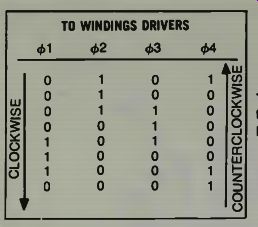
Table 1. The Computer Code to Rotate the Stepper Motor: of Fig. 8 (courtesy
Microbot).
THE COMPUTER INTERFACE
The computer interface is shown in Fig. 9 and it is so designed that it will operate, by changing some internal jumpers, with any 8 bit parallel I/O port (TTL levels). The interface was operated by a Radio Shack TRS 80 Level II computer by the designers of the robot arm. Notice that there are seven 4-bit parallel outputs and a single 4-bit input. The address information is used to channel the four bits of output data to the particular motor drive circuit selected. This is done through individual 4-bit latch circuits. After a phase rotation pattern has been sent to one motor through a given latch, that latch is held until the next phase pattern is transmitted. These latch circuits actually control the transistor drivers, and thus the power which is applied to the motor coils to make the motor step.
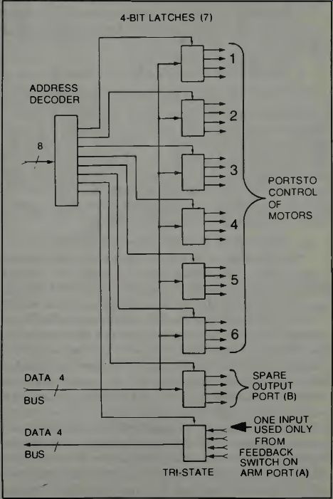
Fig. 9. The computer interface to the motor control circuits (courtesy Microbot)
As we examine Fig. 9 notice several facts. There is one input to the data bus from the arm at port A. There is one spare output (port B) since only six of the output ports are needed for control of the six stepper motors used on the arm.
This output port might be used to control another motor if desired. Also, notice that only one feedback line is used. This is to return a signal from the tension or grip-switch of Fig. 7.
You could have three more feedbacks incorporated in this system if desired, without increasing the size of the I/O port.
THE ARMBASIC COMMAND COMPUTER LANGUAGE
The ArmBasic language, developed to control this robot arm, is an extension of the BASIC language for the TRS-80 computer and consists of the five additional commands necessary for complete control of the arm. The commands chosen are:
• @STEP
• @CLOSE
• @SET
• @RESET
• @READ
Each of these commands is used as a BASIC statement, and interpreted as a Z-80 machine code subroutine. Here is how the designers explain the computer operation.
"The@ STEP command causes each of the 6 stepper motors to move simultaneously. The syntax of this command will be:
@ STEP (D), (J1), (J2), (J3), (J4), (J5), 06) in which statement the D is an expression which governs the delay between steps and the J1 through J6 are the statements for the number of steps each motor is to be moved. The delay expression, which is evaluated as an integer, determines the speed of stepping. If a delay value of zero is indicated the system is set to wait 1.2 milliseconds between each step signal. For each additional unit of delay, the driver system will wait an additional .03 milliseconds between the stepping pulses. Therefore the delay is expressed as: Delay = 1.2 + 0.03 times D milliseconds "To determine which way the motors will step, one uses a plus or minus sign, and the number of steps; the value of the integer for each motor, indicates how far it will actually move, i.e., the more steps the farther it will move the arm." One interesting concept of this system is that there is an automatic compensation for the interaction between the el bow joint and the hand openings. The compensation permits the elbow joint to move while not affecting the hand opening.
In systems where the control motors are mounted right at the joints and are operated by specific signals this may never be a problem, but in a cable driven system, due to the very nature of the cabling, interaction is something that has to be considered and compensated for. The designers point out that the steps J4 and J5 refer to motors which drive the left and the right differential gears of the wrist, so that the relation between the gear positions and the wrist roll and pitch angles must be determined by the user's program.
An important function performed by the @ STEP command is to coordinate unequal motor commands linearly.
Thus if the base control motor is commanded to move X number of steps and the shoulder motor is commanded to move Y number of steps where Y<X there should be in such a system an appropriate number of delays in the Y stepping signal generation so that the timing of the Y steps will correspond, in time, to the X number of steps. If this is so then the arm movement is smooth and flowing, just as your arm movement would be as you reach for a pencil. When the number of steps for each section are accomplished in the same time frame, then the end point segments of the arm will reach their final positions simultaneously.
The @ CLOSE command which is the command which causes the hand (or grippers) to close until the grip-switch is activated and sends back a signal to the computer that the hand has closed with the designed pressure effective. The syntax for the gripper closing is also very simple:
@ CLOSE (D) And the letter D again represents the delay-in-closing time.
We next consider the @ SET command which has a syntax like this:
@ SET (D) This is a very simple syntax arrangement indeed. D is actually the system delay that governs the speed.
The designers state that when one uses the @ SET command it puts the control system into a manual mode so that when you depress the various keys on the TRS-80 keyboard (or keyboard of an equivalent computing system) each joint of the arm can be positioned individually. One keyboard arrangement for controlling the arm is shown in Fig. 10.
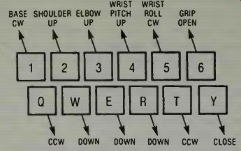
Fig. 10. One keyboard control system for the robotic arm Mini-Mover 5 (courtesy
Microbot).
When you wish to stop this manual mode of operation, you simply depress the zero key. Since the driver for the output is capable of reading all keys at one time, if you hold down more than one key, the arm will move in accord with the combination of signals, i.e., the joints commanded will move at the same time. The motion will continue as long as the keys are held down. To stop the motion one simply releases the keys.
By now you can imagine sitting down at a computer keyboard and carefully depressing the appropriate keys to cause a Microbot arm to move in the manner you desire. By carefully choosing your key and the timing of its depression, you can make the arm move over a block, extend down and grip it, move back upward so it can turn with its load and move it to a new location and carefully stack the blocks as shown in Fig. 1.
It is important to note that as each command is executed, the number of steps commanded for each motor in the arm are counted and stored in a set of registers in RAM. On the video display one can determine the commanded position of the arm under either manual or computer control. There are two commands which access these registers. They are the following:
• @ RESET
• @ READ
The @ RESET command zeros the position registers and stops all current to the motors, thus allowing you to physically move the arm to a new position. Any other command cancels @ RESET, and the position of the arm at that time becomes the new home position.
The syntax of the @ READ command is:
@ READ (V1), (V2), (V3), (V4), (V5), (V6)
Where VI to V6 are any BASIC variables. This command reads the six position registers and transfers their contents into the variables. In this way the current position of the robotic arm is available to the BASIC program at any time.
PROGRAMMING THE MINI-MOVER 5 ROBOTIC ARM
Dr. John Hill, Design Engineer of Microbot, explained the way to program this robotic arm in the Spring, 1980 issue of the Robotics Age magazine.
"To illustrate the use of ARMBASIC in manipulation, we will discuss several methods of programming a pick-and-place task. The task consists of repeatedly picking objects up at one place and setting them down in another. This task is common in industry where parts from a feeder are deposited in another machine or onto a moving conveyor, for instance. To simplify the example, we will assume an unending supply of parts at the pick up point and continual removal of parts at the destination point.
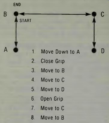
Fig. 11. The robot's arm movements in a Pick-and-Place program of Table
2 (courtesy Robotics Age).
The task is defined in Fig. 10. Pickup is from A and placement is at D. The approach and departure trajectories, AB and CD are usually required for practical reasons: an object resting on a flat surface normally must be lifted before it is translated instead of just sliding it along the surface. In an industrial environment, such a movement could possibly damage the part, the manipulator, or some other object in the workspace.
"A simple sequence of ARMBASIC commands for performing the pick-and-place task is shown in Table 2. Movements are performed by the @STEP command, including opening the gripper (statement 60), P=(P1, P2, P3, P4, P5), Q=(Q1, Q2, Q3, Q4, Q5) and R=(R1, R2, R3, R4, R5) define vectors whose elements are the number of steps of each joint needed to move the arm from A to B, B to C and C to D respectively. S is the number specifying the speed and GR is the number of steps the gripper is to be opened to release the part.
"This simple approach is not very practical, as it requires that the number of steps on each joint be known in advance. One practical approach for small tasks is entering the data manually by moving the arm to each of the four positions (A, B, C and D of Fig. 11) and letting the computer count and remember the number of steps each joint moves. This operation is frequently called "teach mode." The teach program shown in Table 3 illustrates this principal. Operating interactively with the computer, the operator manually positions the arm to each of the four positions to specify the pick-and-place task.
Each position is obtained by moving the arm, joint-by joint, using the keys in the upper left hand corner of the keyboard as previously described under the @SET command. Even the desired grip opening is conveyed by teach control. Only the speed is entered numerically.
"After the arm is positioned at each of the four locations, the values of the software position counters are read by the @READ command and stored in the vectors A, B, C and D. The elements of these vectors, A=(Al, A2, A3, A4, A5), B=(B1, B2, B3, B4, B5), C = (C1, C2, C3, C4, C5), and D = (D1, D2, D3, D4, D5), are the values of the position counters of each joint. The P, Q, and R vectors of the simple program (Table 3) can therefore, be obtained by subtraction as follows: P=B-A, Q=C-B, R=D-C. The desired grip opening, GR, is measured by reading the grip position counter before and after closing the grip using the @CLOSE command. (Statements 170-200 in Table 2.) Examine Table 4. For this program, the locations of the four positions of the pick-and-place task (A, B, C, D) are defined by their Cartesian coordinates (see Fig. 3). The x, y, z, coordinates (in inches) and pitch and roll angles (in degrees) at the fingertips are: A=(8, 0, 0.5, -90, 0) B=(8, 0, 1.5, - 90, 0) C=(6, 5, 1.5, - 90, 90) D=(6, 5, 0.5, - 90, 90)
Table 2. Simple Implementation of ARMBASIC Pick-and-Place Program (Courtesy Robotics Age).
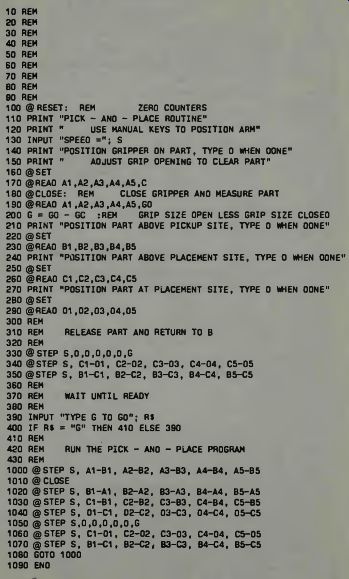
Table 3. The Mini-Mover 5 Teaching Program (Courtesy Microbot).
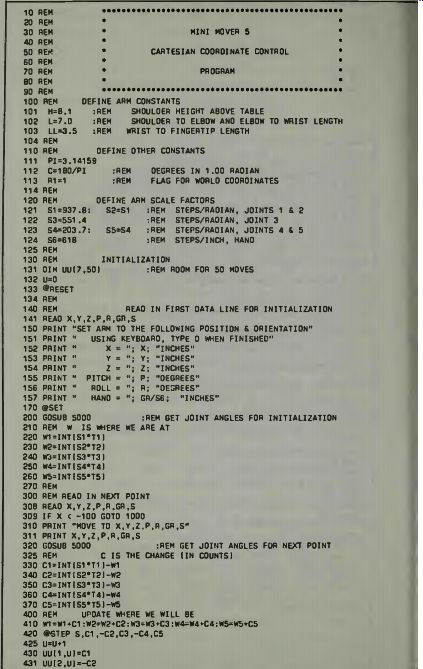
Table 4. A Cartesian Coordinate Program for Mini-Mover 5 (Courtesy Microbot).
Note that the object is gripped at a point 0.5 inches above the table top (z=0) and is raised (or lowered) 1.0 inches for lift off (set down). Its x location is changed from 8 to 6 inches and its y location changed from 0 to 5 inches. The angular orientation of the gripper is always straight down (pitch-90 degrees), but the object is rotated 90 degrees on its vertical axis between pickup and set down (roll changes from 0 to 90 degrees). "Data for the Cartesian coordinate program is located after statement 10000. Each data statement specifies an arm position and orientation in terms of x, y, z, pitch and roll, and also includes a sixth parameter, governing the grip opening (if positive) or squeezing force (if negative) after each move, and a seventh parameter governing the speed setting during each move. The actual arm solution, beginning at statement 5000, takes an arm configuration specified by the variables X, Y, Z, P, and R, and finds the joint angles (in radians) that would place the arm in that configuration. It also includes several tests to determine if the position and orientation requested is within the reach of the arm.
"The first data statement gives the initialization point, which is used by the initialization phase of the program, statements 140-260, to tell the computer where the arm is in the coordinate system. Note that the arm position registers are not used by the program (although the @ RESET is necessary). Instead, the operator is instructed to position the arm at the initialization point under control of the @SET command. The joint positions corresponding to that point are computed and stored in variables W1-W5. In the main part of the program, the relative offsets from one point to the next are computed and used to step the arm. Thus, all arm movements are made relative to the initialization point.
"Since the computer has no way of measuring the arm's joint angles upon startup, such an initialization must be made by every program that relies on an external coordinate system. Similarly, all arm movements are made "open loop," or without position feedback. Therefore, a re-initialization is necessary if the arm is unable to successfully perform a movement due to overloading of collision. The use of open loop control by stepper motors eliminates the need for joint position sensors and associated interface circuitry and is thus an important design tradeoff that reduces the cost of the arm while still providing accurate positioning.
"During the second phase of the program, statements 300-530, the arm is moved from data point to data point as the solutions are carried out. An arm solution takes less than one second. The joint angles corresponding to each data point are stored in array UU. After all the solutions are obtained, control is transferred to the third phase, beginning at statement 1000, where the pick-and-place cycle is run repeatedly without coordinate conversions by using the joint angles in UU. "Those who analyze the Cartesian coordinate pro gram carefully will note that it is, in fact, general purpose, capable of generating arbitrary motion trajectories with up to 50 movements. This is sufficient for many assembly tasks such as building structures from blocks.
The power of the ARMBASIC approach can be seen by comparing the simplicity of this program, which is less than 100 lines of code, with previous approaches which have required 8K or more of assembly language coding to do the same type of task."
ROBOTIC-ARM ACCURACIES AND POWER
The Mini-Mover 5 was developed for, and can be used in learning and teaching, and in an experimental way to verify computer related concepts economically. From this view point, it is an impressive device. From a useful standpoint of doing work it has some limitations which need examination.
One of these limitations is the power capability of the arm.
There can be no doubt that in advanced robotics applications a significant amount of power must be generated, proportional to the size of the robot of course, to enable the machine to do useful work. One may argue that useful work is, indeed, a good reason for the machine's existence. Another problem of machines of Mini-Mover 5 design may be the physical control cabling because it has, by virtue of its type, some play and elasticity which becomes more pronounced as it attacks jobs which require power and force for handling. This seems to defeat one much-desired goal of robot machine development; that of consistent and reproducible accuracy to an extremely high degree of precision in a repeatable process requiring movement. Cables give much flexibility in construction and in many cases simplify such construction. However, they may not produce the feedback effect of inertia in an automated system as much as gears do.
Certainly, if one does not have to have motors and gears at each joint, the system inertia can be reduced for operational and computational analysis purposes. One might then avoid the complexities of having a variable moment of inertia to be concerned with when the robot arm is moved.
Currently the accuracy of robot arm device positioning is limited to some .004 inch in a repeatable processing cycle.
While a higher degree of accuracy may be needed in some types of applications, we must admit that .004 inch is not bad!
COMMUNICATING WITH THE ROBOT
In the example of computer communication using the operation of Mini-Mover 5, hard-wire signal cabling was used. We do not have much to worry about as far as getting extraneous signals into the machine's operation, unless we are very careless and lay the signal cable in a strong electromagnetic field, improperly shield it, make the signal cable too long, or improperly terminate it at either end. Usually, since the signal cabling is relatively short in length, properly laid, terminated, and even may be shielded, there is no problem, and the signals are transmitted strongly and accurately.
If we have a robot located at some distance from the computer which directs its operations, and if the environment through which signal cables or lines to the robot must be laid is harsh, as far as signal transmission is concerned, then we could have a communications problem. The problem evolves around two concepts; the loss of signal information, and the production of spurious signal information.
Loss can be due to actual signal disintegration or to distortion to such an extent that the robot cannot tell that it is receiving a command or feedback signal. In an industrial environment two possibilities exist.
The robot with its drive motors is the end unit and the computer, servomechanism amplifiers, and such are all located at a remote point away from the robot. Thus the only signals going to the robot itself will be the voltages necessary to cause the motors to operate, and since these are high level signals they are less subject to interference. The second possibility is that the robot is almost entirely self contained and thus, with its integral computer and servo system, is relatively well protected from a harsh communications environment. In this latter case, the robot receives signals from its own world only, be they commands from the computer program, or feedback from its working sensors.
When the robot is in a fixed location, the wires connecting it to a remote computing and electronic control mechanism panel are usually contained in metallic tubing which gives physical protection and shielding if such tubing is connected to a common ground. Even then, a shielded cable may run inside this kind of conduit. In this type of application this usually takes care of the communications problem. In fact, in industrial plants, the use of hard-ware signal cables might be the most useful way to communicate with the robot, and have it communicate with its control base! But, for a moment, let us examine the possibilities of having a communication with the robot by radio signals.
If you are familiar with the antiaircraft missile systems used by the Department of Defense, then no doubt you will be concerned if we do not also point out that in these fine systems, the information concerning the target can be obtained by the ground station, independently of the missile.
The missile is really a controlled robot projectile of the robot ground station complex.
The point is that two way communication with a robot is essential. We send commands, we get feedback information from the robot's sensors. The computing section of the system analyzes the data, modifies the commands in accord with that data and sees to it that everything works as it should, for as long as it should, in the proper sequence, and with the proper timing. The computer coordinates various machines and perhaps other robots in doing a job so, the computer must get feedback from each robot.
Think of the amount of information a complex operation must have moving over a communications system! This in formation must not be distorted or modified or lost in the process, and it must be very visible to the computer in whatever noise levels may be present in that communications system.
We are constantly amazed at the human capability to distinguish desired information in an environment of undesired information. For example, three persons may talk at the same time and you want to follow the intelligence of just one discussion. The human mind, once given the command to listen to Joe, turns its attention to what Joe is saying, excluding the other voices as far as interpreting intelligence from them. The head turns to give Joe's voice the best reception and to minimize the reception of the other voices. The mind then instantly develops a pattern of information based on snatches of words which it recognizes clearly. The mind will actually fill in words and phrases and sentences which are incomplete due to competing noises or distortions. If the mind gets lost, it commands the tongue to activate and ask "What? What did you say?" So it is with robotic communication systems. By using the binary code and making words out of the infinite number of patterns of these symbols, sounds, or signals (in which-ever form they may appear), one might loose some elements and still not lose the message. That is a required and desired level of operation for robot machines.
Suppose that a signal comes which has the following form 110110110100. The zeros underlined for emphasis mean that no pulse of energy appeared at that time. The question then is whether a pulse of energy was there and was lost, or whether a zero was actually intended at that time. If we suppose that the computer receiving the signal can look at the word received and calculate that for this word to fit into the intelligence pattern of the phase, the first zero has got to be a one. It makes a one out of that space and the word has meaning in its phraseology. Everything continues in a fashion.
With humans, the loss of letters-say with a Morse code message-can easily be filled to make sense. Suppose you receive the following; Th_ _an was tall. You supply the missing letters to get "The man was tall."
MULTIPLEXING IN COMMUNICATIONS SYSTEMS
Multiplexing means conveying many different items of information on the same path. If we use a hard wire system we know that we can send many different types of signals over a single pair of wires, and each signal, or set of signals, can be representative of information from a single source. Thus we can have, with multiple signals, multiple information from many sources sent over the same pair of wires.
Some elementary means of conveying different items of information are to use a modulation procedure, or use a time division of the use of the lines. In the first case, since, usually, frequencies are involved, we think of this system as frequency multiplexing. The second system, as you would suspect, is called time multiplexing.
Examining frequency multiplexing further we find that we can send many items of information simultaneously, since we can modulate a carrier (be it wire, radio signal, light beam, or whatever) with many different signals simultaneously. An example is our regular broadcast radio system. We know that the musical tones of different instruments-say, for example, the piano, saxophone, clarinet, drums, and a vocal-can all be sent at the same time and we humans can distinguish each instrument by its tone. For control purposes it was a practice some years past-and still is in some systems-to send tones denoting commands or information and separate them electronically at the receiving end with audio filters low frequency rf filters. It is understood that a command can be an off-on or present-absent type of thing. The presence of a tone can cause a switch to close and some electrical or electronic function to be performed when this happens. The absence of the tone will mean switch open and a cessation of that functional operation.
It is also understood that to convey a changing bit of information, such as we might need in a robotics application, that we cannot have just an off-on type of signal. The feedback from sensors must be such that they can be varied in some way to produce information about slight changes in position, or values of the object being sensed.
The tone transmission system can vary the pitch of the tone slightly around some nominal value, and a slight change can convey the information we desire to be sent to the computer decoding section. The decoder must then change a variable pitch, or tone, into some kind of machine signal such as off-on pulses which the computer can then use to do its assessment and evaluation and computation with.
So, we are now looking at bands in the tone spectrum over which signals might be varied to convey changing information. These bands all might be sent simultaneously and so we then ask ourselves if there is a limit as to how much information we might send simultaneously. We can reduce the band widths by going to higher and higher tone or signal frequencies. We find that there is a limit to how many tones we can transmit simultaneously and still recover the desired information. Scientists who have studied this problem estimate that eight audio channels is about the limit each channel getting only 12% of the available 100% modulation capability of the transmitting system.
Think of what this means. If we are dealing with a single robot, which has many self contained feedback functions, and some kind of internal computing and directing system, eight feedback channels to some outside and coordinating might be sufficient. But if that computer is directing many robots, and needs a lot of information from each to properly effect that coordination, then eight channels is certainly limiting! So we look at Time Division Multiplexing.
It seems right away that this has some advantages. One particular advantage is that each channel can get the full 100% modulation since it is singly transmitted. When the information from one channel has been sent, then the second channel's information is sent, and so on. If we can send the information fast enough, we can send lots of channels, each getting the full operational capability of the transmitting system, and, as far as the practical operation of the robotics system is concerned, if the information is sent fast enough, it won't even know that it is getting its data in spurts.
In a way, a computer already operates with this concept of time division multiplexing, for it has common busses which are time allocated to various signals by a timing clock. Thus we begin to look at robots as just another I/O peripheral. If we want to go one step further, we can imagine a combination system, using time division multiplexing and frequency division multiplexing over a common carrier which should enable us to get all the information needed from one point to another to make remote operation of robots very practical.
SOME EXAMPLES OF PULSE CODE MODULATION
To summarize the previous discussion, we are interested in the feasibility of operating our robots remotely, without the use of hard wire cables to them, or operating the robots using a single pair of wires instead of multi-cables such as we have learned are used to operate most robot arms.
Examine Fig. 12 wherein we see a graphic representation of some forms of pulse modulation which might be used to convey intelligence from one point to another. The carrier might be a wire, a radio transmitter, a light beam of any frequency, or even sound, which may extend from the audible range into the supersonic. We see how a signal might be modulated by extending or shortening the time of existence of the pulses. This is called pulse width modulation. Notice that some of the pulses graphed are wide and some are narrow and realize that a single pulse will be varied about its nominal width with the signal we desire to convey. If, for example, we wanted to transmit just ones and zeros, we might set up a system where a wide pulse represents a one and a narrow pulse (narrower than the nominal value) represents a zero.
Transmission, then, of computer readible intelligence would be just long strings of wide pulses and narrow pulses to make up computer words. The diagram does not reflect accurately, the number of channels being transmitted. If, for example, we use a five bit word for commands and feedback, we would have only one channel of communication. We have to define a channel as being the route to a single operating unit. Thus in the case being discussed we would have only one channel, which might mean control of one robot. We could imagine that we would send many sequential lists of five bit code groups and thus, using time multiplexing, control many robots in this manner.
If we restrict ourselves to the width-per-pulse as a channel, as illustrated, then we find that five pulses represent five channels as shown. The width variation might be interpreted as ones and zeros as we have stated, or by varying the width in a sinusoidal manner we could recover tones and tone variations which could represent variables in the system. The manner of varying the width of a pulse, such as illustrated, is left entirely to your own imagination and requirements, one might recover saw-tooth or square-wave or exponential waveforms from the varying tonal modulation. This tone modulation or variation might be a real variable on a rf carrier, or it might just be a recoverable value from the varying rf frequency.
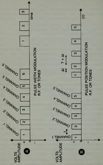
Fig. 12
There is a difficulty. If we lose a pulse we have lost a channel. If the system, somehow, is able to cause pulse existence shortening or lengthening, we have spurious in formation being generated. If rf is used as the carrier, it may take some bandwidths to accommodate the variation in pulses. However, on the good side of the situation, this system has been used successfully in commercial applications and in hobby applications where it is used to control radio-controlled model aircraft. It is relatively easy to design a decoder to separate wide pulses and narrow pulses.
In the second possibility the pulses all have the same width and are all transmitted sequentially. It is the relative position of each pulse with respect to a starting time for the "train" which governs its information carrying content. As shown, we assume that when no information is being trans mitted, each pulse has a definite existence time, following some type of input starting clock signal. Since each pulse can be varied about this nominal existence time, being either early or late one can relate these positions to coded data.
Early being one, late being zero. With robots such signals can also mean up arm, down arm, and neutral arm position.
This is the system of transmitting command and control signals used with the GARCAN robot discussed previously in this guide. It is a simple and reliable and well understood method of sending commands. It can be used for both off-on functions and proportional functions.
The code shown in C can be a direct representation of the binary words used in computers. One simply has to have enough pulses to match the computing system used; i.e., an 8 bit system needs 8 pulses, but one might have 12 or 16 or 32 or even 64 pulses if that kind of accuracy is needed. If the pulses are microsecond or fractional microsecond existence units, and are separated in time by fractions of a microsecond, it would not take long to send a 16 or 32 pulse word or train of pulses. This word could be repeated over and over, just as a message could be repeated to insure accuracy. There is probably some probability mathematics which would indicate just about how many times, on the average, one should repeat a word to be assured that it would be properly received, but we won't go into that here.
We find in C a system made to order for transmission of binary code. We assume that signal presence-or pulse presence-means a one and absence of the signal means a zero. Therein lies our difficulty. If we lose a pulse in transmission, the computer on the receiving end might interpret this to mean that a zero should be written. The computer thus might be incorrect! But, as we have stated, redundancy might overcome this problem to some extent, and computer sentence analysis could also be used.
Finally, we glance at D wherein we find the basic radio teletype system of frequency diversity used to convey ones and zeros. Two tone frequencies can be transmitted over a common radio frequency carrier, or other type carrier, such as previously indicated. One tone means a one, and the second tone means a zero, as shown. Since the system must always have one or the other tone being received, any absence of tone means an error which the computer can recognize. As we know, this system has been found to be highly accurate and reliable in the transmission of messages. It would be relatively easy to apply this system to robotics applications and, using filters, and combination or pairs of tones, one might control many robots, or robotic functions over a single wire pair, or rf frequency.
SOME DESIGN CRITERIA OF TELEMETRY SYSTEMS
Measuring the responses of a robotics system by remote means is similar to getting information from an experimental aircraft or rocket in flight using radio systems and sensors at various critical points in the system. Thus, a few moments consideration of telemetry design criteria can be helpful in our study of establishing communications with robots.
We know that radio telemetry systems have been used in aircraft to measure such things as position, velocity, acceleration, and aircraft attitude with respect to some gyroscopic coordinates. Also, sensors are used to determine the amount of vibration or flutter at various points on the body and the pressure at various points internally and externally. They also measure temperatures, strain, stress, fuel flow, cosmic ray counts, ionization, static build-up, and voltages through out the aircraft. Of course such measurements can be made on other vehicles as well. Our space explorers are robots that send back pictures, and after testing and sampling distant planets, information on soils, atmosphere, and such is also sent.
When we consider the return of data, we must also consider the accuracy of that data and whether it meets the design and operating criteria or not. Data from such systems may vary quickly and considerably, or it may vary slowly and within small excursion limits. If we are looking just for general information then, perhaps, accuracies within, say, 15 to 40 percent may be used and acceptable. But if we really want tight monitoring then we will want accuracies within, say, 1/2 to 2 percent and in some cases, as in a robotics system where positioning is being monitored, we may want accuracies from 0.1 to 0.001%! Of course we would like absolute accuracy; zero percent error if possible. But due to system limitations we just can't reach that optimum.
When we are interested in some sensor value which may vary at a sinusoidal rate, it has been found necessary to sample that quantity with at least 3 samples per cycle, and it has been said that you must have at least six samples per cycle to reconstruct a varying sine wave with any degree of accuracy. Of course, if you want to transmit data that is constantly being measured, as you would if you used a frequency varied by the sensor, then you should have total information instantly, concerning that measured unit. If you use a pulse sampling system wherein the pulse voltage amplitude is then converted into digital (binary) words which can be used by a computer to reconstruct the wave being sampled, there is always the possibility that the sampling system might miss something-some variation-if that sampling is not conducted frequently enough.
In accepted telemetry systems which use tone or low rf frequencies to modulate a carrier (usually an FM carrier to reduce noise and distortion), the system is called an FM-FM system. This means frequency modulation of the oscillator which, in turn, is frequency modulating a carrier.
The oscillator, of course, is being modulated or varied by the sensor measurement unit. If one wishes to think in terms of computerized handling of data, then one thinks in terms of receiving pulses which form groups of binary computer words as we have already mentioned. Analog to digital circuits are available and can be used in such an application. The accuracy will be governed by the number of samples-per-second taken of the measured or sensed quantity. A representative telemetering system of the FM-FM type is illustrated in Fig. 13.
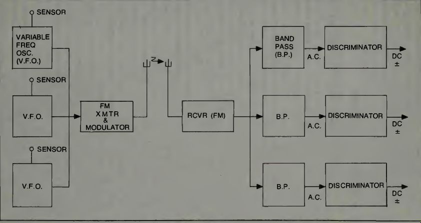
Fig. 13. A representative FM-FM telemetry system.
In the illustration we see some sensors which cause the frequency of the oscillators to change according to the movement, strain, velocity, or whatever is being sensed. This signal is then used to FM modulate the transmitter. It is sent to the receiver, there separated by band-pass filter sections converted into varying levels of plus or minus dc voltages which are proportional to the instantaneous position, strain, or velocity of the sensed unit, and then sent to analog-to digital converters and thence to computers. Of course these signals might be used in their analog form to control a remote robot or whatever.
COMMUNICATIONS SIGNALS NEEDED
It is essential that regardless of the type of carrier which conveys information to the robot, this carrier must also be capable of returning signals from the robot to its control station. We think of a simple, proven example. If one has a guided missile whose control station and computing station are on the ground, and the mission of this missile is to destroy enemy aircraft in flight, then the missile should, under some circumstances, be able to inform the ground station how close it is to the aircraft it seeks as prey. When it is close enough, the ground computer will determine an exact time to detonate a warhead for destruction of the enemy aircraft. The signals might also be used to drive pen recorders, printers, or illuminate video displays, as desired, in the operation being conducted.
It is interesting that there are some 18 frequency bands, made up of frequencies from roughly 350 Hertz to some 70,000 Hertz which can be used in FM telemetry. One must make sure that he does not use two bands which are harmonically related, as that plays havoc with the system's ability to give out good data. Variations in frequency are relatively small, usually about 7.5%, and of course, the higher the band frequency, the higher the frequency response capability of that particular sensing section can be.
Thus, when we consider the use of robots which are not fixed in a given location, we think in terms of systems of control which can radiate a roomful of signals which can be received at any place in the area or room, and getting back responses from the robot in the same manner.
The reference system in which all movements are determined is the instantaneous position which they might have at that moment, probably with respect to the four walls and floor and ceiling of the room, and with respect to whatever objects may be within the room, even to a consideration of other people who also may be moving! The feedback sensor system must give you (or your computer) this data. In an automated robotic system with free wheeling robots in action, some computer somewhere must know everything about everything and keep this knowledge accurate and current!
CURRENT SOCIOLOGICAL THINKING ABOUT ROBOTS
To many people, not well enough informed about automation and robotic technology, or incapable of completely understanding just how these machines work, the existence of robots present them with a threat. To some it is a job-loss threat, to some it is a much more serious threat such as; "Will robots take over and rule the world making us slaves?" We may grin about this, but, be assured, such thinking exists in no small dimension. The Robotics International Organization defines a robot as "A reprogrammable, multifunction manipulator designed to move material, parts, tools, or specialized devices through variable programmed motions for the performance of a variety of tasks." One can see, in this definition, a description of a machine and that may be a big help to industry when they plan the utilization of these devices. It may help out with the psychological problems of people.
There are many fantasies concerning robots and these become more prevalent when we consider the robot in some kind of human form. For some reason, that seems to be what the average person would like for his robot to have. One of the leading Science Fiction writers, Isaac Asimov has written of a situation where a mother becomes jealous of a robot who was assigned a baby-sitting task over her daughter, in the story ROBBIE. In another story he described the relationship between a wife and a robotic butler. Movies have been made which show humans falling in love with robots. Why people would be attracted to robots that are, to all appearances, duplicates of themselves, or of "beautiful people" can be the subject of another study. We just pose the idea here for consideration.
In all pseudo-science stories concerning robots we find that sooner or later, the "Laws of Robotics" are derived or stated. These laws are supposed to be the statements which govern the limits of robotic action. Isaac Asimov formulated and first wrote the Laws. One of these is paraphrased "The robot shall not harm his maker." Designers were supposed to insure, in the circuitry associated with the robot, that this Law was embedded and used as a control on the robot's operations. Now we find that there is an effort to state some Laws for industrial robots, and since these, in a way, reflect thinking concerning the use of industrial robots, we should examine them. As stated by Neale W. Clapp of Block Petrella Associates, one set of such Laws are:
(a). Organizations may not install robots to the economic, social, or physical detriment of workers or management.
(b). Organizations may not install robots through devious or closed strategies which reflect distrust or disregard for the work force, for surely they will fulfill their own prophecy.
(c). Organizations may only install robots on those tasks which, while currently performed by men, are tasks where the man is like a robot, not the robot like a man!
This decade is the beginning of the age of robotics, and thus, while we are learning how to make them operate, and what they can do, and how to make them better from a design and operational standpoint, perhaps the sociological aspects of robotics showed also be a prime area of consideration. This could also influence the design, installation, development, and operation of these types of machines.
HOW SOME EXECUTIVES DETERMINE THE NEED FOR ROBOTS
W.R. Tanner of Tanner Associates has stated some rules of thumb by which an executive might determine if he is on a correct course when he installs robots in his installation.
(a). Avoid extremes of complexity (b). Operations must be orderly and systematic (c). Remember, robots are generally no faster than people (d). For short runs use people, for very long runs use fixed automation (e). If it doesn't make dollars it doesn't make sense (f). One is not better than none (g). If people don't want it, they won't make it.
Refer to the Spring, 1980, issue of Robotics Today magazine for Mr. Tanner's discussion.
Some of the ideas expressed in the rules seem suitable, and others are open to question. We would question f as it seems that a detailed consideration of the application might be in order before making a judgment such as stated here. If a robot can be operated 24 hours a day (not considering down time), and if it requires no breaks or rest periods, and if it can be adjusted to perform new tasks with relative ease, then perhaps just one robot in an installation can add up. You will determine, from your own experience and knowledge, which of the other rules might be appropriate, but we would venture to suggest that some debate might be worthwhile on some of these rules. We have included some of the previous rules and definitions to illustrate that industry, as well as users of other types of robotic equipment, seem somewhat frustrated when they really begin to consider such machines in the hierarchy of human-machine relationships. When we think of an automobile, we simply think of transportation. It can be with or without comfort and conveniences, and it can be cost effective or not. It can be status making or demonstrating. But we know where and how to think of that kind of machine, both in a pleasure sense, and in a profit producing capacity. We also know how to relate the human element to the machine, even if it is a variation of the automobile, such as the truck, tractor, tank, or whatever.
Perhaps we must come to the same type of thinking with robots? Is it possible that one status symbol of the future will be the number of domesticated robots one has around the house? It is possible that the industrial profit margin will be controlled by the number, type, and efficiency of robot workers. It is possible that one might find a completely new type world in which the human must be re-programmed to be compatible with the robotic machines which he previously programmed?
As I write this guide I wonder what the future of writers will be. Will a robot typewriter investigate the many areas of research by simply sending signals over the telephone lines to libraries and other repositories of knowledge; analyzing and assembling and developing material and then spewing out pages of text? Perhaps it would write novels, based on tried and true plots, or screen scripts? Man may tend to forget, and a computer can memorize almost forever. Man may be emotional in rendering judgments, a machine will just consider facts. Man may be unable to render perfect decisions, due to his inability to retain or consider all facts needed to get the absolute picture of background, trends, or whatever. A computer, with the new technology making possible a larger and larger memory capability, and with the computer ability to solve equations relating to the decision making process that baffled man in years past, we, even currently, note how many humans are turning to these machines for the answers to their problem.
In any event, we need to know as much as we can about these robotic computer-controlled things and to this end we now continue into the next section where we consider first another industrial robot, and then some aspects of giving robots eyes. You might even begin to think about the situation we have now, where most robots are blind. What will the ability to see mean to these machines?