AMAZON multi-meters discounts AMAZON oscilloscope discounts
One unique feature of this robot is that it is an all electric system. As illustrated in Fig. 1, you can see the large, specially designed electric motors on each side of the arm at the shoulder position, and one to the rear of the arm section.
Also visible in the illustration is the control panel which governs its operation. At the right end of the arm itself is an attachment disc which permits use of a multitude of tools or devices to do the various tasks for which it is designed.
Notice that while the arm itself is not directly extendable, reach can be obtained by use of the electric motors at the shoulder position, or by causing the arm to bend at the elbow rotary joint. This is very similar to the human arm.
When we examine such an arm and realize its strength and capability, it brings to mind a vision of a sleeping giant and helpers as illustrated in Fig. 2. In this illustration we at tempt to show that only a portion of a robotic capability, perhaps, is being used to assemble or adjust some objects brought to it by, in this illustration, elves, who position and hold the workpieces while the arm performs its operation on them. Then they move on to the next robotic station. This, of course could be some type conveyor system, but one which has a positioning capability at the end where it meshes with the arm operation.
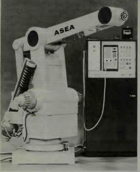
Fig. 1. The ASEA robot for industrial applications (courtesy ASEA). Fig.
2. One arm benign giant (robot) and helpers.
As to the giant itself, note that only a small portion of the possible computer brain has been used, and that a second arm remains motionless. In some applications there is a need for a second arm, or even a second pair of arms and some robots have been designed to have these appendages. Underwater repair of cables or oil lines use such robots to perform working tasks. Our giant gets his orders by telephone or more accurately, by electronic-electrical signals. Maybe it's a little fanciful but it is intended to illustrate a point. The ASEA robot is made by the Electronics Division of ASEA, Västerás, Sweden. More than 600 of these type robots are being used in various types of industrial applications in more than 20 countries. The tasks which it performs range from moving a stainless steel sink around a polishing brush, to delicately applying liquid adhesive glue to a car top, to applying a multi torch welding unit to car bodies. This robotic arm has six degrees of freedom to do the tasks assigned. Notice in Fig. 1 how well sealed the whole unit is, and that makes it possible for it to operate for long periods of time in dirty environments where grime and other contaminants may exist. In one de-burring application a vicious stream of tiny metallic particles is generated during the working process.
The arm must not be affected by them. Each electric drive unit includes a complete servosystem with a dc motor, resolver, for positioning indication, and a tachometer for controlling its speed. It is said to have a quiet operation.
What we gain by examining this unit is a further under standing of just what an industrial robot consists of, how it is programmed, how it operates, and what it can do. Since this arm is electrically driven, it also can provide a giant example for the hobbyist or experimenter as to how electric motors are, and can be, used in such an applications, and how they are controlled and regulated. Smaller motors, of course, would be used in smaller arms.
In the description which follows we must realize that the robot arm is described as having a lower arm section which is that section connected to the base pedestal, and an upper arm section which is the horizontal member attached to the lower arm section. The robot can rotate about its base pedestal and the motions of the arm segments will be angular about their pivot points, but this angular motion can result in an in-out motion of the end wrist to which various tools and devices can be attached. The wrist is the small circular section at the right end of the horizontal upper arm in Fig. 1. Its rotation is perpendicular to the rotational up and down movement of the upper arm. In this robot the designers have used an ingenious system of linkages to accomplish wrist rotation. Now let us learn some details of this robotic arm.
DESCRIPTION
The ASEA industrial robot system is made up of three main parts: Control system Measuring and servosystem Mechanical system The control system consists of the computer, memories, inputs and outputs to control the robot and interlocks from peripheral equipment, and functions to control the servo system of the robot.
The measuring and servo systems include servo amplifiers and dc motors with tachogenerator feedback. Position regulation is by means of a cyclic resolver system consisting of a resolver with associated supply and decoding circuits, and a position regulator.
The mechanical system includes the robot and the transmission which converts the rotation of the motors into the required motion. The following motions are available:
Rotation (phi) entire robot rotates about its pedestal
Out/in motion (theta) lower arm moves
Up/down motion (alpha) upper arm moves
Wrist bend (tau) the wrist bends up or down
Wrist turn (v) the "cuff" of the wrist rotates
Various additional units (options) can be connected to the control system of the robot:
A programming unit, which is used to program robot motions
A tape recorder unit, used to store programs on magnetic tape cassettes
Standby battery supply, ensures that the contents of the program memory are maintained up to 45 minutes after loss of supply
Memory module to increase the size of the program - memory Test panel for servicing and troubleshooting
Solenoid valves for gripper operation
Gripper
The control system is based on a computer, as shown in Fig. 3, which illustrates the main communication paths in the system.
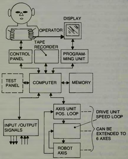
Fig. 3. The block diagram of the robot system of ASEA (courtesy ASEA).
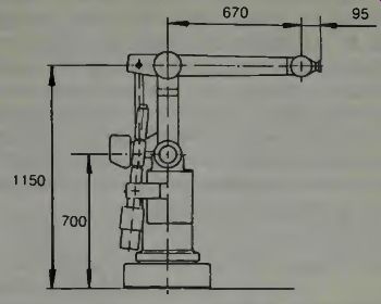
Fig.
4. Dimensions of the smaller industrial robot arm with a 6 kg capacity (courtesy
ASEA).
A control program is stored in the memory. This pro gram, which is fixed, tells the computer how the various robot instructions and control functions are to be performed. The operator and control system communicate via the control panel and programming unit. The computer regularly scans the state of the controls and reads out acknowledgement orders by switching lamps on or off. The computer monitors and controls input/output signals between the process and the control system, and reads out orders to the axis units if travel is required on any axis.
The operator programs the robot with a particular pat tern of motions by means of the programming unit. Each move is commanded by the operator using jog buttons and the position and speed are stored in the computer memory. The conditions for process signals (e.g., for gripping tools and external acknowledgements or interlocks) can also be programmed and stored in the memory. When the program is complete the operator can operate a control on the control panel to order the computer to store the program on magnetic tape. The program can then subsequently be read in from the magnetic tape and stored in the memory of the computer. A robot program stored in the memory can then be started and continuously repeated or stopped from the control panel on the order of the operator.
We have mentioned that a robotic arm should be capable of doing work, and thus it requires power. ASEA makes two robotic arms seen in Figs. 4 and 5. One is much smaller than the other (IRb-6vs IRb-60). It is now of interest to use to see what some technical specifications are with respect to weight handling capability, degrees of freedom, and gripper capabilities. In many applications the speed of arm movement can be very important. Thus we also examine this capability.
Remember that as the size, and thus the inertia, of an arm increases, more power is required to make it move quickly, and also much more attention must be given in the servo system to the damping function to insure that the arm will not overshoot its required positions, and that it will not hunt or oscillate about an end-point position.
Power
Robot | IRb-60 | IRb-6 6
Permitted handling weight including gripper:
Maximum gripper length at above handling weight:
kg 60 kg 200 mm 400 mm
In order to calculate the permissible handling weight when the gripper length exceeds 200 mm or 400 mm as the case may be, the following mechanical data apply:
Maximum moment of inertia 2.5 Nm^2
Maximum static load 12 Nm
100 Nm^2
240 Nm
The robot is available with the following degrees of freedom: Arm motion: rotation
Arm motion: radia
Arm motion: vertical
Wrist motion: bend
Wrist motion: turn 340° 9..-. 40°
+25° to -40°
±: 90°
:L-. 180° 330°
+50° to - 20°
+10° to - 55°
+75 to - 120°
-±- 180°
Gripper functions:
Two independent solenoid valves housed in the upper arm, which can be operated from the keyboard of the programming unit, are available as an option. There is also a four-pole electrical outlet in the upper arm; among the intended applications of this is the supply of more advanced grippers with search functions.
Weight of robot: 125 kg 750 kg
Repeat accuracy at wrist: - ±0.20 mm - ±0.40 mm
Speeds: Arm motion: rotation 95°/s 90°/s
Arm motion: radial 0.75 m/s 1.0 m/s
Arm motion: vertical 1.1 m/s 1.35 m/s
Wrist motion: bend 115°/s 90°/s
Wrist motion: turn 195°/s 150°/s
Every robot arm has a working envelope or area through and in which the arm can be programmed to move. We show the profile of the IRb-60 in Fig. 6. Again notice that the dimensions are stated in metric units.
Description of Motions
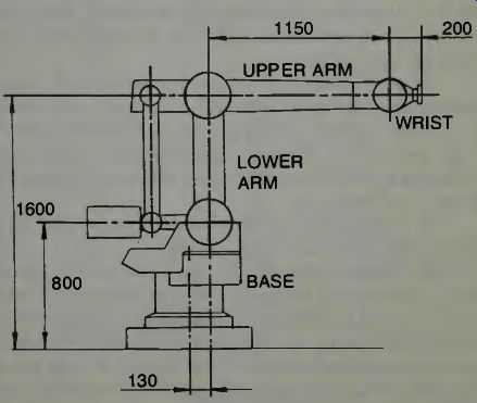
Fig. 5. Dimensions of the larger industrial robot arm with a 60 kg capacity
(courtesy ASEA).
The basic version of the robot has three degrees of freedom for positioning the hand in space. The three main coordinates are a rotary motion (4)) and two arm motions in the vertical plane, performed by a lower arm (9) and an upper arm (a). All three main motions are position-controlled by means of dc motors. A further two degrees of freedom are available as options, a wrist turn and a wrist tilt version.
These motions are available either with dc drive or with pneumatic rotary cylinders with mechanical limit position stops. In the basic version these motions are mechanically blocked.
The drive unit for the rotary motion is rigidly mounted in the pedestal and drives the body around the pedestal column through a reduction gearbox with a very low ratio. See Fig. 7.
The drive unit for all coordinates except the rotary motion (4)) are mounted on the rotating body. The arm motions are provided by ball-screws which actuate the arms via links and levers. The lower arm (0) moves the wrist horizon tally in and out. The motion remains completely horizontal since the a-motion compensates for the 9-motion by means of the control system. In the same way, the motion of the upper arm (a) is compensated so that its motion moves the wrist vertically up and down.
The wrist motions are driven via a system of linkages which is designed so that the wrist coordinates will assume the set angle to the horizontal plane regardless of whether the θ- or α-coordinate changes. The drive units for the wrist motions are mounted on the frame at the lower bearing point of the lower arm.
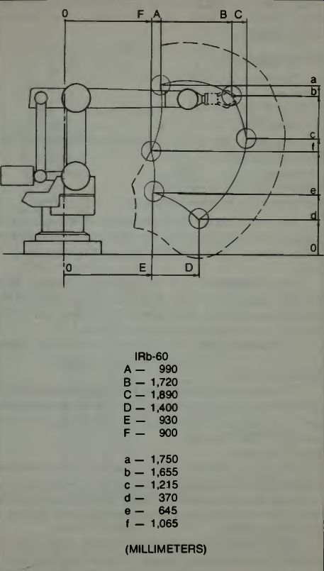
Fig. 6. The working profile of the IRb-60 robotic arm (courtesy ASEA).
The wrist is also designed in such a way that tilting always takes place in the vertical plane.
The driving system for this arm consists of dc electric motors. It is easier to design a driving system to produce variable speeds and torques using dc motors than it is using ac motors. When using ac one must have modulators, and de modulators and phase comparers and such. With dc motors one simply uses high powered transistors or similar solid state drivers. Since signals from computers are dc this also makes the whole system more compatible, electrically. In Fig. 7 we show the drive unit locations and some definitions. A unit as stated here is an electric motor. Inspect the wrist motions and notice that both turn and tilt are accomplished.
Drive Unit Analysis
The drive units consist of:
Motor unit
Mechanical transmission
Servo-amplifier
The motor unit of the basic version is made up of the following components:
Dc motor
Resolver for position indication
Tachogenerator for speed regulation
The motor unit for the wrist turn or tilt motions can be replaced by a pneumatic turning cylinder, two versions of which are available, one for 90° turn and the other for 180° turn.
The transmission is of two types, the harmonic-drive gearbox or the ballscrew unit. Each motion is described in the following pages, which also deal with the transmission, that is the way in which the motions are achieved.
The servo amplifier is installed in the control cabinet together with the rest of the electrical equipment.
Pedestal:
The pedestal is in the form of a baseplate with a cylindrical top; it is an aluminum casting. The cylindrical part houses the motor unit and a harmonic drive gearbox for the rotary motion (φ ). See Fig. 8.
Body:
The body is coupled to the output shaft of the φ-motion drive unit. It is also mounted on a bearing in the pedestal and rotates on this (the (φ -motion). Mounted on the body are the drive units for lower arm motion (0-motion) and upper arm motion (α-motion).
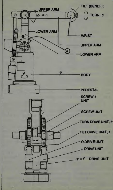
Fig. 7. The drive units of the IRh-60 and some definitions (courtesy ASEA).
The electrical wiring from the control cabinet is connected in the pedestal by means of connectors and passes from the pedestal to the body through coiled flexible leads between the pedestal column and the body.
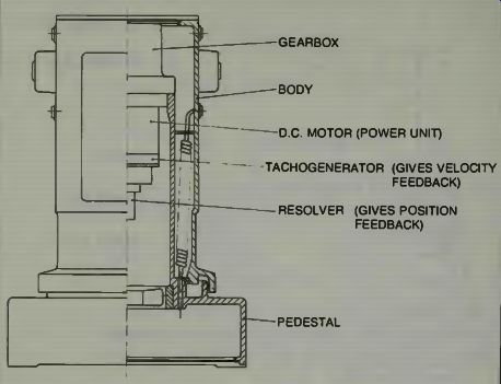
Fig. 8. A cut-away view of the robot's pedestal (courtesy ASEA).
In this illustration we see that the left hand side is the enclosed part which shows how the body and pedestal appear as you view them, such as in Fig. 1. On the right half of the illustration the internal location of parts and devices is shown.
Notice that the tachogenerator which we call a tachometer which is really a small generator which produces a voltage output exactly proportional to its speed and which is used in the damping of the system, is an integral part of the motor unit. The resolver (we sometimes call them selsyns or synchros) will give a signal (ac) the phase of which is directly proportional to the instantaneous angular position of the body with respect to the pedestal. This is used for position feed back in a servosystem. A dc resolver is a potentiometer and it is sometimes used in servosystems.
Next we begin an examination of the moving sections of the robotic arm and the gripper unit. Notice that small lever arm sections are located near some rotating joints so that a motor driven screw can exert the force necessary to move the arm section. The manner in which this driving force is exerted is easier than using the motors directly connected to the joint through a complex gear train as necessary in a direct-driving system. (In many cases direct-drive is used, and very successfully.) The screw-type lever-action motion shown in Fig. 9, approximates a hydraulic type piston motion. But the reserve oil tank, the valves, and the pressure pump and use of oil are eliminated which may be a cost factor.
Speed of motion is reduced over that of a hydraulic system, and perhaps some power capability is lost when using electric motors in this arrangement. Look at Fig. 9.
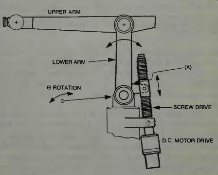
Fig. 9. The lower arm motion system of the ASEA Robot arm (courtesy ASEA).
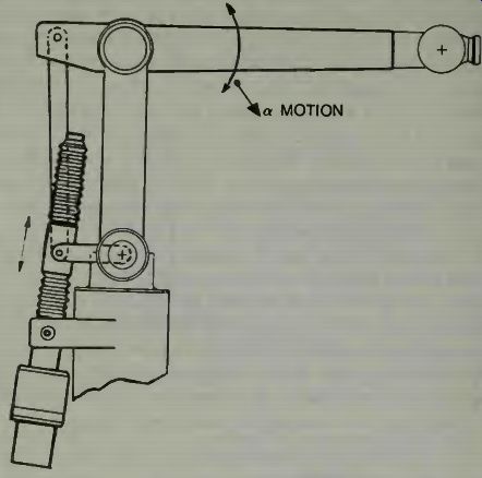
Fig. 10. The upper arm motion system and drive assembly for ASEA robotic
arm (courtesy ASEA).
Mounted on the body is a bearing bracket to which the lower arm is fixed and in which it pivots. The motion of the lower arm (0-motion) is obtained by means of a drive unit consisting of a motor unit and ballscrew transmission; these are rigidly mounted on the body. The motion of the ballscrew is transmitted to the lower arm via a lever pivoting at the ballscrew and attached to the lower arm. The drive units for the turn and tilt motion of the wrist are mounted on the lower arm around its lower turning centre, see Fig. 11.
The upper arm description and operation are as follows: The upper arm is fixed to, and pivots on, the upper end of the lower arm. Movement of the upper arm is achieved as follows.
The drive unit, consisting of the motor unit and the ballscrew transmission, transmits a motion to two link rods articulated on a shaft extending from the ballscrew nut assembly. One of the link rods is attached to a shaft fixed to the upper arm and the other end is attached at the center of rotation of the lower arm. Together with the upper and lower arms, these two link rods form a parallelogram. As Fig. 11 shows, movement of the nut assembly and one corner of the parallelogram will move the wrist up and down.
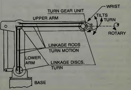
Fig. 11. A schematic diagram of the wrist linkage system for ASEA Robot
(courtesy ASEA).
Electrical and compressed-air lines to control the grippers run through the upper arm. At the rear of the arm there is a connection for the supply of compressed air. Outlets for the gripper, two individually controllable pneumatic outputs and an electrical contact with four wires are mounted on the underside at the front of the arm.
The wrist is rigidly mounted on the upper arm. Two motions are available at the wrist, a turning motion and a tilting motion. These motions are achieved as follows. The drive unit for each motion can either be a dc motor equipped with a resolver and a transmission consisting of a gearbox, or a pneumatic rotary cylinder for turning at right angles or 180°. With pneumatic power, only one motion can be driven and the other must always be locked. The motion of the drive unit is transmitted to the wrist via a linkage system.
The linkage system operates as follows, Fig. 11. A linkage disc is coupled to the drive unit, which is mounted on the lower joint of the lower arm. Mounted on this linkage disc are two link arms displaced π / 2 rad (90°) on the linkage disc.
The other end of the link arms is mounted on a linkage disc pivoting in the upper arm. From here the motion is transmit-ted to a linkage disc in the wrist via two more link rods. The turn and tilt motions have separate linkage systems on either side of the arm system. Wrist tilt is achieved because the linkage disc at the wrist is fixed to the moving part of the wrist. Wrist turn is achieved by means of an angled gear unit which transfers the motion from the linkage disc to a turning disc, free to rotate in the wrist. The angled gear unit is adjustable so that subsequent adjustments can be made in cases requiring very little backlash.
Figure 11 shows the linkage system in the lower arm and upper arm. In the basic version the disc for the tilt motion at the lower joint of the lower arm is mechanically locked, so that the wrist keeps a given angle relative to the horizontal plane regardless of arm motions. The turn motion is mechanically locked at the wrist itself.
Mechanical stops are rubber composition. There are mechanical limit position dampers for all motions, to prevent damage to the mechanical components of the robot if, because of faults in the control system, the robot motions should exceed the working range. The dampers are of rubber and are designed to damp the full motion speed without deformation of the mechanical components.
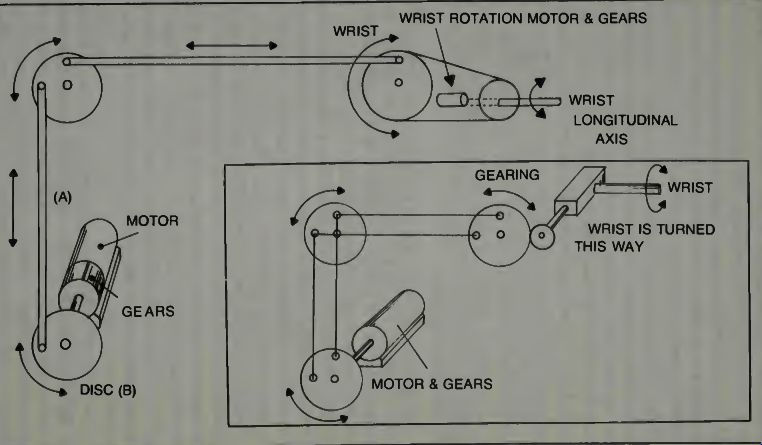
Fig. 12. A simplified diagram of the ASEA linkage motions.
A SIMPLIFIED DESCRIPTION OF THE LINKAGE MOTION
While ASEA uses two linkages from one disc to another in the actual machine, the drawing (Fig. 11) is difficult to analyze to see just exactly how the discs rotate to cause a movement of the wrist. In Fig. 12 is a simplified look at how this can be accomplished. If you follow the arrows and consider that the motor output rotation through the gearing will be limited to somewhat less than 90 degrees each way from the neutral position shown, then you can see how the output disc to which the wrist is attached will move up and down as the motor driven disc is turned. Of course, the motor might just have a small lever output to move the linkage up and down (A) and not need a disc (B) at all in this first position.
It is essential that the discs and motor shaft be fixed to the robot's body so that no movement up or down, left or right will occur. If they move physically, then they cannot transmit the rotational movement which we need at the wrist. Also, you can consider another set of such discs and another motor and some additional linkages which can be so positioned that when this second motor is rotated each way somewhat less than 90 degrees, it can cause the wrist to turn sideways, back and forth. Thus we have the movements needed for back and forth and up and down. The rotation or turning of the wrist about its own axis can be accomplished with an integrally installed motor at the wrist position, said motor to be turned and tilted when necessary, and when activated, it can, through its own gearing, provide a rotational movement 90 degrees one way and 90 degrees the other way, of the wrist, or whatever is attached to the wrist. It would be advisable, of course, to provide electrical limit switches on the wrist so that the motor cannot overdrive it past the 90 degrees positions. Examine Fig. 12.
We recommend that if you are deeply interested in this linkage situation, you might contact some mechanical engineering student, or friendly professor, at a nearby university and question them about Fig. 11. A second source of information on linkages of various types, pantographs, etc., can be found in your local library under mechanical devices or mechanical engineering mechanisms. Ask the librarian to help you locate a good reference work if you need it.
No one has said that a robotic arm is a simple device, it just looks that way! Actually there is quite a bit of mechanical, electrical, and computational equipment installed in such a unit. Examine a block diagram of the ASEA robot system in Fig. 13. The legends are in English and Swedish so a brief explanation of the operation will help tie all the various blocks together.
The control electronics consist of circuit boards which make up a computer with a memory. There are also interface boards for data communication with the various input and output units, i.e. tape recorder, control panel, programming unit and axis units. The signals between the function modules of the control electronics appear at the rear plane of the electronics rack and are in the form of a data bus, memory address bus, address pointers for the various input and output units and a small number of clock pulses and control signals.
The digital input and output signals for the control panel, programming unit and external process go to the input/output unit via the terminal unit. An analog reference signal, the polarity and value of which indicate the direction and speed of movement of the robot axis, is generated in the axis unit. The analog reference (command) signal is amplified in the drive unit so that it can control the dc motor.
The computer included in the control electronics can be divided up into five main sections.
*Input for reading-in data from the process (feedback)
*Arithmetic unit for arithmetical and logical data processing
*Memory to store both data read in from the process (feedback plus command signals) and the robot system control program
•Control functions to check what is to be executed
*Output for the supply of data to the process
The arithmetic and control sections consist of the function modules known as the central unit (A) and the interruption and power failure detection unit (B). These units contain a clock pulse generator to generate clock pulses to the control section and other electronic sections, a microprocessor and circuits to control a general bit data bus for data transmission between the microprocessor, memories and input and output units. The microprocessor contains, among other things, an arithmetical-logical unit, an instruction decoder and a program counter. The instruction decoder interprets the instruction read from the control program of the memory and establishes the conditions for the execution of the required operation. The program counter keeps track of the order in which the computer instructions in the control pro gram are to be carried out.
The memory, which may be either of the write/read type or of the read type only, consists of various combinable function modules, depending on its size and type. The memory is organized in memory words of eight bits each. A total of 16 k (16,384) words can be addressed.
There are two electronics modules for the computer memory: the memory unit and the PROM-unit.
The memory unit contains a 4 K (4,096) word write/read memory. The write/read memory is a semiconductor memory which stores the robot programs programmed by the operator. It defines the patterns of motion of the robot, that is, data for position coordinates and speeds, and the control of digital inputs and outputs. The second variant of the memory unit, with write/read memory only, is used to increase the memory space for the storage of robot programs.
The PROM-unit, which contains a 7 K (7,168) word read memory, stores the control programs of the systems. The memory content of the PROM-unit does not change in normal service, but it can be re-programmed with a special programming unit.
Finally there are the input and output units: these are the tape recorder interfacing, axis control circuits and input/ output unit. The tape recorder interface controls data transmission between magnetic tape and the memory. The "axis control circuit" function unit receives data words which state by how many increments the relevant robot axis must move.
The purpose of the input/output unit is to match words on the bus system of the computer to signals for controlling and checking panel controls and external relay and contact functions. For reference voltage supply of the measuring transducers on the robot, the reference counter and resolver amplifier function unit will be required. A test panel for servicing is also available, as shown in Fig. 13.
OPERATION
As Fig. 14 shows, the basic program for controlling the robot system is divided up into a number of subprograms. The start-up routine is always activated after switching. Among other things, this clears the registers and program counter.
The clock pulse routine synchronizes the computer with the 10 ms sampling period used in the robot system. Whenever the clock pulse arrives, a jump to the clock pulse routine takes place, and at the same time the conditions of a group of controls are read in. While automatic running is in progress, a jump back to the automatic routine always takes place, so that new movement data are read out during the next sampling period or at the beginning of execution of the next robot instructions. In other cases a jump takes place to the mode selection routine. This routine investigates which load is required and whether any related operator actions have been taken. If so, a jump takes place to the routine for the selected mode: if not, the system jumps back to the clock pulse routine to await the next clock pulse.
The manual routine deals with all operator actions relating to the manual mode and required for robot programming, program corrections, synchronizing the robot and step-by step running during program testing. For example, when the routine is complete, the system jumps to the clock pulse routine, except in step-by-step running, when it jumps to the automatic routine in order to execute the robot instruction.
The automatic routine selects which robot instruction is, in turn, to be executed. After this, each robot instruction has its own sub-routine; in other words the automatic routine includes a total of 16 sub-routines.
Finally there are the routines "read cassette" and "write cassette", which carry out reading of robot programs to, and transfer of robot programs from, the magnetic tape cassette.
After reading or writing is complete, the system jumps to the start-up routine.
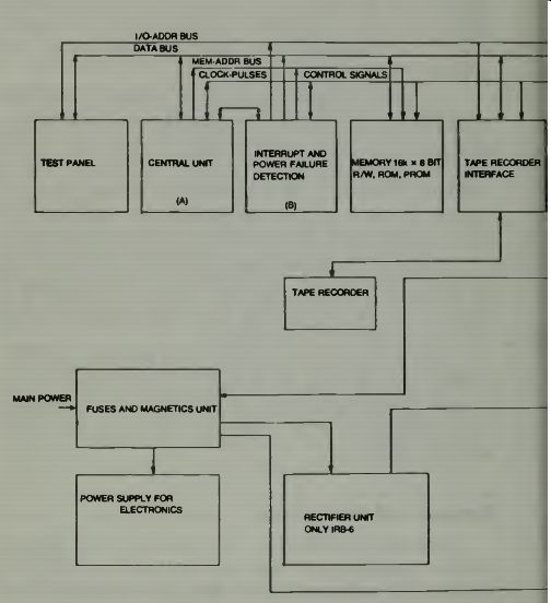
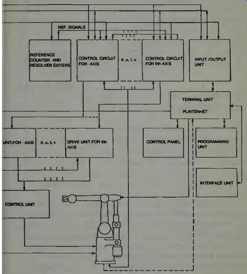
Fig. 13. The block diagram of the ASEA robotic arm (courtesy ASEA).
Feedback and Servosystems
Each robot axis is fitted with a feedback resolver for axis position measurement. The resolver has two fixed stator windings and one rotating rotor winding. The resolver stator windings must be supplied with two reference voltages with the same peak-to-peak value and 90° out of phase. The frequency is 2 kHz. The voltage induced in each rotor winding is filtered in the appropriate "axis control circuit" function unit.
The phasing of the basic frequency of the resolver response is a measure of the position of the axis. The resolver is coupled to the -drive motor shaft, and one motor revolution corresponds to 200 increments.
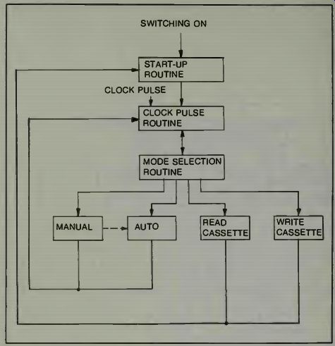
Fig. 14. The flow chart of the ASEA robotic system (courtesy ASEA). A desired
value signal with a frequency of 2 kHz is generated electronically in the "axis
control circuit" function unit. The measuring system operates on a phase-analog
principle, meaning that the phase difference between the actual value signal
from the transducer and the desired value signal is directly proportional to
the position error. The function unit contains a converter which converts the
phase difference to an analog error signal which controls the servosystem.
During axis motion, the computer regularly reads out orders which result in phase-shifting of the desired value signal. A phase difference between the desired and actual value signals will cause the robot axis to move and therefore the resolver to rotate in order to reduce the phase difference.
During motion at constant speed, the axis lags behind the commanded value with a particular lag which increases with speed. On starting and stopping, the acceleration or retardation is controlled automatically in such a way as to prevent overshoot.
The "axis control circuit" function unit contains two circuits which monitor the value of the lag. The condition of these circuits is scanned regularly and read into the computer. If the lag exceeds a certain maximum permitted value, emergency stop takes place and the robot stops. The second circuit detects whether the lag is within a few robot increments, the zero zone. During fine positioning with the robot, the next robot instruction does not begin until the axis has taken up position, that is, the lag is less than the zero zone.
Servoamplifier
The servoamplifier is part of the position control system. In IRb-6 it consists of a transistorized chopper and in IRb-60 a thyristor converter is used.
The drive units of all axes in IRb-6 are supplied by a common power supply rectifier; see Fig. 15. The positive or negative supply voltage is supplied to the drive unit motor circuit at a frequency of about 1 kHz. The motor voltage is controlled by varying the pulse length. Figure 15 shows the block diagram.
In IRb-60 the ac voltage is fed directly to the drive units after reduction by transformer as shown in Fig. 16. The drive unit is a conventional thyristor converter with a circulation current reactor. The current and speed are controlled in the same way as IRb-6, but in this case by controlling the firing angle of the thyristors.
In both versions there is an inductor connected in series with the motor; the purpose of this is to reduce current pulsations due to the pulsating nature of the motor drive voltage.
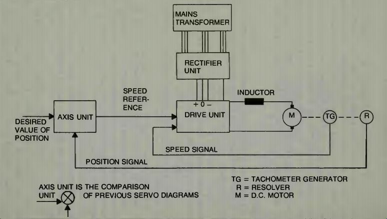
Fig. 15. The block diagram for one axis of the ASEA robot. Notice that both
position and velocity feedback are used (courtesy ASEA).
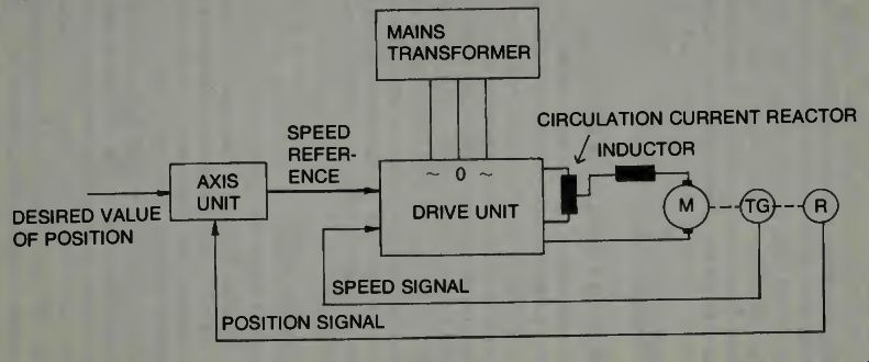
Fig. 16
An analog error signal which serves as the speed reference for the drive motor is obtained from the "axis control circuit" function unit. The actual speed is measured by a tachogenerator coupled to the drive motor. The speed reference is compared with the tachogenerator voltage in the speed regulator of the drive unit. The difference is amplified and used as a reference for the motor current. A pulse shaper then controls the transistor switches to give the required direction of motor rotation and the required speed.
In IRb-6 the smaller robot system, the motor current is monitored by a circuit in the drive unit and if the current exceeds its critical value for more than 5 sec., this circuit ensures that the current is reduced to a safe value. This function is used to protect the system, when for any reason, the robot arm comes up against a mechanical limit position.
The motor circuits of both IRb-6 and IRb-60 are fitted with a thermal release which causes an emergency stop when the motor temperature goes too high.
GIVING THE ROBOT A SENSE OF ITS WORLD
There used to be a saying that "mobile object knew where it was because it knew where it had been." It's true! Everything is relative. If a robot arm does not know where it has been, how can it know where to move next? To give the robot a sense of its working world, that is, to give it some base coordinates from which to measure its movements, and then to give it well defined programs in its coordinate system results in a fine state of robotic well being.
It will then be able to make moves in coordinate system you have selected. We now examine how a world is defined for the ASEA robotic arm.
THE ASEA ROBOT'S WORLD
In order to enable the patterns of motion of a robot program to be defined relative to the rest of the peripheral equipment the robot must be set to a well-defined position before the program starts. This takes place on synchronizing to the reference zero point of the robot. When an order for synchronizing is given, the robot axes begin to move at a fixed speed in a positive direction. The axes move until a synchronizing switch-one for each axis-is actuated; when the switch closes, the axis continues to the nearest resolver zero, or electrical reference zero point. On synchronizing to a reference zero point, the position registers of the axes are updated so that none of the robot axes can be run up against a mechanical limit position. These position registers are stored in the memory. The working range of the axes is stored in the control program, and if any axis attempts to exceed the value, the motion is interrupted and a warning lamp lights up.
The robot can also be synchronized to its actual position.
This means clearing the position error for a brief instant on the "axis control circuit" function unit. This takes place when the robot is switched on, to prevent the robot jerking when the drive motors engage, and on emergency stop, for rapid stopping of the robot.
LOSS OF MEMORY POSSIBILITY WITH MICROCOMPUTERS
It is a constantly possible horror story. Somehow the electrical supply system to the plant or robot was interrupted and the inevitable result was that the memory lost all of its information! It is not necessary that the supply voltage be lost entirely, sometimes this might happen if the supply voltage drops below a critical level. Of course there are other possibilities which might affect the robot's computer brain such as temperature extremes, static, and in case of discs, dust and dirt. In the case of a good robotic system an alternative supply is incorporated into the system. This is how the ASEA robot system handles the problem: Since the program memory is made up of semiconductor circuits, the stored information will be lost if the +5V supply falls below a critical value. To eliminate the necessity for reading the program from the cassette after brief supply voltage failures, the control equipment is available with standby battery supply for the program memory. The blanking plate on the control panel is then replaced by a maintenance-free battery unit. A standby supply unit must also be fitted to the control equipment. The program memory receives its +5 V supply from the battery. If the mains voltage is available, the battery is continuously charged from the standby supply unit. These are the technical data of the battery package:
Life expectancy at least 3 years
•Capacity with maximum program memory equivalent to a mains voltage failure of at least 45 minutes
•Charging time for discharged battery, approximately 6 hours.
A red indicator lamp on the battery unit lights up if the battery is discharging. There is also a switch to disconnect the standby battery function for expected long disappearances of the mains supply voltage if, for example, the main switch is off.
If the voltages for the electronics section of the control equipment disappear or if their value becomes incorrect, either too high or too low, this is detected by a monitoring circuit, and the mains voltage to the control equipment is switched off. Only the standby power supply unit (where fitted) continues to receive mains voltage in order to maintain the battery charge.
The system includes a circuit which monitors the voltage supply of the program memory. If at any time this voltage falls below its critical value, a flip-flop is set and a warning lamp indicating loss of program lights up on the control panel when the mains voltage is restored. The pro gram must then be re-written into the memory.
SIGNAL TRANSFERENCE IN THE ASEA ROBOTIC SYSTEM
There are tapes and recorders used to store programs and other types of data and these are conventional so we won't spend time on this aspect of the system except to note that they are used and have the normal advantages and disadvantages. We also realize that from the control rack of any robot system, a multitude of signals must pass to and from the robot and its brain section. We have discussed this to some extent in the previous sections. Here is an actual working example system for us to examine with respect to this important area.
Signals pass between the control cabinet and the ASEA robot for the following:
Dc motors
Resolvers
From three to six
Tacho-generators electrically-controlled
Synchronizing switches axes
Solenoid valve
For pneumatic control of tilt or turn and 6th axis (replaces electrical control)
Limit switches
Grippers 1 and 2, which are controlled by solenoid valves
Ac-operated grippers or alternatively, search devices with an acknowledgement signal
Connection leads to connect the programming unit to the robot Protective earthing of robot In order to match the control equipment for various applications it may be necessary to duplicate a number of important control functions and to control external units or detect various acknowledgements. The available signals with maximum voltage and current data are listed below. All input and output signals are filtered to suppress electrical interference. Shielded cables must be used for the input and output signals, and the leads must be connected to terminals in the cabinet. The cabinet wall has a sealed entry for the external cable. Following is a description of the external connections of this system.
Output signals, 4 contact functions
*Contact closed if control equipment is operating (220 V, 1 A)
*Contact closed when the OPERATION pushbutton is pressed (24 V, 200 mA)
*Contact open on emergency stop (220 V, 1 A)
*Contact open when the EMERGENCY STOP pushbutton is pressed (24 V, 200 mA) Input signals, 3 contact functions
*Open contact gives emergency stop (24 V, 1 A)
*Contact closure gives "program start" (24 V, 10 mA)
•Contact closure gives "program stop" (24 V, 10 mA)
The contact closure function for "program stop" has priority over the "program start" function.
Output signal to drive relays
.14 outputs numbered 1 to 14 The relay driver stages, which are current-sinking, are designed for +24 V and 150 mA maximum. The total current in the output stages must not exceed 2 A. The programmed outputs are used in automatic running.
Interlocking inputs for the robot program
•16 inputs numbered 1 to 16.
The input stages convert the contact functions or signals from current-sinking driver stages into logical signals suit able for the control equipment. A contact or current-sinking driver stage must be capable of connecting 10 mA to 0 V and must be dimensioned for +24 V. A 2.5 ms filter circuit is provided to eliminate the effect of contact bounce and high frequency interference.
The programmed inputs are used in automatic running.
Gripping tools and search devices signals and connections
The standard version of the ASEA robot is supplied with electrical wiring to a socket on the robot arm for the connection of search devices or other types of grippers. Different connections must be made in the control cabinet depending on the function for which the socket is to be used. The following signals are available, depending on the application.
a. Connection of search devices
•=f- - 15V to supply search device electronics (max 0.5 A)
*Input to control system for the "search-stop" function.
The search-stop contact or transistor must be dimensioned for + 24 V and be capable of connecting 10 mA to 0 V.
b. Connection of valves to control grippers
• 2 make contacts (220 V, 2 A)
• An option unit must be added to the control cabinet.
Two solenoid valves to operate two pneumatically con trolled grippers are also available as extra equipment. The valves are controlled by signals from the control unit.
Compressed-air lines inside the upper arm are fitted to the robot as standard.
The procedures in checking cables for proper signals and to check these cables for broken wires and/or bad connections in sockets is the same as for any large piece of electronic equipment. There are many relays used in this unit and these must be maintained so that they provide proper connections between their moving points and the fixed points. Cleanliness, spark prevention, reduction of pitting, and heating are some areas which must be considered. Sealed relays or solid state relays tend to reduce problems in relay maintenance and in the switching of large voltages and small signal voltages in any robotics system.
CONTROLLING THE ASEA ROBOT
On the control equipment there is a control panel with controls to start the industrial robot system and to select various operating modes. For normal operation of the robot system, that is, when the robot is programmed, only these controls are required. If the equipment has standby battery supply of the program memory, the battery package is mounted in a module on the control panel.
What the Control Switches Control
Switch Function
MAIN SWITCH
To switch the power supply on and off
a. 1 Power supply connected to robot system if MAINS ON is alight.
b. 0 Power supply switched on.
Content of program memory will be lost unless standby battery supply is provided.
PROGRAM SELECTION 1-4
The control system can store programs in its memory. The 1-4 switches are used to select the programs in automatic running and when programming a new program, or when using the tape recorder. A yellow indicator lamp lights up for the selected robot program(s).
a. OFF - This program is not used.
b. ON This program is connected
BATTERY
a. OFF
b. ON OPERATION STANDBY
The switch is on the battery unit and is used to switch the standby battery supply function on or off.
Standby supply of program memory from battery is switched off.
The battery is switched on and supplies the program memory in the event of power supply failure, to prevent the content being lost.
Power supply connected to robot motors. Yellow indicator lamp lights up. Control system is in the operation condition.
Starts the control system after power supply has been switched on or after disconnection of the supply voltage for the robot motors. Yellow indicator lamp lights up. The control system is in the standby condition.
SYNCHRONIZING
A red indicator lamp lights up after the power supply has been switched on or after emergency stop.
If the button is held pressed the robot axes go to their synchronizing position.
EMERGENCY STOP RESET EMERGENCY STOP
Immediately stops all robot motions and sets the system in the standby condition. The EMERGENCY STOP lamp lights up.
This pushbutton resets the emergency stop circuit if the contact circuit which caused the emergency stop has been closed again.
OPERATING MODE
There are four pushbuttons with yellow indicator lamps for operating mode selection.
a. AUTO Automatic operation with one or several programs to be executed consecutively in order.
Yellow indicator lamp lights up.
b. MANUAL
Manual mode. The robot can be synchronized, or operated and programmed by means of the controls on the programming unit. Programs can be tested step-by-step. Yellow indicator lamp lights up.
c. READ CASSETTE
d. WRITE CASSETTE
A robot program can be read in from the magnetic tape cassette.
Transfer of a robot program from the program memory to a cassette tape. Yellow indicator lamp lights up.
PROGRAM START
PROGRAM STOP
In the automatic mode, the robot program starts. In the manual mode an instruction is executed whenever PROGRAM START is pressed. The pushbutton is also used to start reading from, and transfer to, tape cassette in the "read cassette" and "write cassette" modes. A green indicator lamp lights up during activity.
In automatic mode, stops the robot program in progress; in manual mode stops the instruction which is being executed.
The PROGRAM START indicator lamp goes out. In the "read cassette" and "write cassette" modes the tape recorder is stopped.
POWER ON Yellow lamp lights up if main switch is closed and power supply voltage is available.
PROGRAM LOST Red lamp lights up to indicate that the content of the program memory has been destroyed.
EXCESS TEMPERATURE Red lamp lights up to indicate excessively high temperature in control cabinet.
OPERATOR ERROR
Red lamp lights up for incorrect operation of controls, e.g. if a switch is set to the wrong position or if an incorrect mode is set.
EMERGENCY STOP BATTERY OPERATION
Red lamp lights up after an emergency stop has taken place or after internal emergency stop initiation from the control system.
This lamp is situated on the battery unit and gives a red light when the battery is discharging.
TEACHING THE ASEA ROBOT
In an earlier section we learned how a hand-held unit can be used to make the robot arm go through the desired motions to accomplish a task. As the arm gets into various positions we press a learning button which causes that information to be placed in the computer's memory bank. In essence the arm is jogged or wiggled into the various positions it must have to do the tasks as you teach it what to do. You jog or wiggle the arm by depressing various buttons on the hand held unit. It follows your every command and the process has a fascination all its own. In a way it is like steering a radio-controlled model airplane or car or boat by slight movements of the joystick or the steering wheel. But this is a big and powerful unit which, once it has learned its job, will then, when put into automatic operation, perform that job for you almost endlessly! And do it with a constant precision and speed that always makes those concerned with budgets smile broadly! So be it. Let us see what happens when we program the ASEA robot.
PROGRAMMING THE ASEA ROBOTIC ARM
The portable programming unit which can be plugged in at the control cabinet or at the robot, is used to re-program the robot for new applications. When the robot is working in the normal operating mode the program unit can be used in conjunction with other robot systems. The robot is program med by using the pushbuttons on the programming unit to nm it to the positions it is required to take up in automatic operation. Each position is stored in the program memory when an instruction key on the programming unit is pressed.
In addition to positioning instructions, it is possible, for example, to store in the program memory instructions for the operation of grippers, opening and closing of a number of outputs, testing of a number of interlock inputs, time-lag and repeating. The programmed instructions are then executed in sequence in automatic mode. The programming unit is shown in Fig. 17.
In order to avoid tedious reprogramming after long periods of power supply disconnection, or when more than four programs are to be used with the robot, programs can be stored on cassette tapes.
Some interesting aspects of the remote control panel are section D, which controls the arm, and E which has the control buttons for the wrist. Notice how the movements are designated on this panel. Numbers have been added to the button faces to make it easier to discuss their individual operation. Look at section D first.
Greek Name Capitol Letter Lowercase Letter
Alpha A a =
Theta O 0, /9
Phi 4130 Z = p = yo
Upsilon Y /, Tau T r (7)
Buttons one and two control a rotary movement of the arm assembly by rotating the base structure. Refer to Fig. 7 where the Greek symbols for the angles are shown. The control of the lower pivot of the arm is accomplished by buttons 3 and 4, and the control of the upper segment of the arm is with buttons 5 and 6. For the wrist section (E) buttons 1 and 2 control the tilting of the wrist, while the buttons 3 and 4 control the rotation of the wrist clockwise or counterclockwise.
Since the angles in Fig. 7 are expressed in Greek letters it might be of help to review this symbology. The following short table shows the letters used.
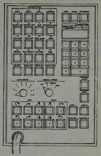
Fig. 17. The remote programming unit for the ASEA robotic arm (courtesy
ASEA).
Now, having identified each of the pivoting joints and the directions of motion of the arm segments and the wrist itself.
Let us examine what the other buttons do in the following table. Notice that you must sometimes push two or even more buttons, and set a dial switch to a proper setting in order to get the arm ready for whatever kind of commands you want to give it. It can be instructive, if you want to get a feel for programming of a robot arm such as this, to imagine that you have the remote panel before you--look at Fig. 17--then look at the robot arm in Fig. 6 and see if you can write down which buttons had to be pushed and in what sequence in order to make the arm move through each of the positions shown. Of course you might also imagine some positions of your own choosing and write down the button pushing program to get the end point of the arm to those positions. You can also imagine that grippers are attached and include in your pro gram the steps necessary to grasp and move something from one place to another. Try it! In the following table you will find what everything does on the control panel. Some statements will require some thinking and analysis on your part, but it will be worth the effort.
THE CONTROL PANEL Switch AUTO SPEED MANUAL SPEED Function
Selection of speed to be programmed for positioning in automatic mode. In automatic running of program, the highest speed is limited to the speed to which this switch is set. In step-by-step operation the speed is limited to not more than speed 6. Position 8 gives maximum speed
Posn 7 gives 75% of max speed Posn 6 gives 50% of max speed Posn 5 gives 31% of max speed Posn 4 gives 13% of max speed Posn 3 gives 5% of max speed Posn 2 gives 2.5% of max speed Posn 1 gives 1.3% of max speed
Speed selection for manual operation of the robot. The motion is executed by means of the ARM and WRIST pushbuttons.
a. INCR
b. LOW
c. MEDIUM
d. HIGH INSTRUCTIONS
a. 1 PTP F
b. 2 PTP C
The relevant robot axis moves one increment
The relevant robot axis moves at 1.3% of maximum speed
The relevant robot axis moves at 15% of maximum speed
The relevant robot axis moves at 50% of maximum speed INSTRUCTIONS is a group of pushbuttons used to program the instructions to be executed when the robot is operating automatically. On programming each instruction in the program is given a serial number. The instructions themselves are designated by a type number from 1 to 16.
Point-to-point operation with maximum accuracy. With arguments (special numerical values) search and vertical/horizontal running can be program med.
Point-to-point operation with coarse positioning. With arguments (special numerical values) search and vertical/horizontal running can be program med.
c. 3 PTP L
Straight-line operation such that positioning is concluded simultaneously for all axes. The travel time is stated in the form of an argument.
d. 4 GRIPPERS The states of the grippers, i.e., "on" or "off" are stored.
e. 5 OUTPUT ON The digital output (1-14) selected on the keyboard must be "on."
f. 6 OUTPUT OFF The digital output (1-14) selected on the keyboard must be "off."
g. 7 WAIT Waiting time as set on the keyboard (0.1 - 9.9 s).
h. 8 PROGRAM End of robot program. Restart END from first instruction or jump to next program.
i. 9 TEST WAIT
j. 10 TEST OUT
k. 11 TEST JUMP Wait until the interlock input (1-16) selected on the keyboard is "on". Jump to next program if the interlock input (1-16) selected on the keyboard is "on"; otherwise continue with next instruction.
Jump over next instruction if the interlock input (1-16) selected on the keyboard is "on"; other wise continue with next instruction.
1. 12 JUMP
Jump to the instruction number selected on the keyboard.
m. 13 REPEAT
Repeat the sequence the number of times keyed in on the keyboard. This instruction also marks the beginning of the sequence.
n. 14 END REPEAT Marks the end of a repeat sequence. The system jumps to the next instruction when the sequence has been repeated the programmed number of times.
o. 15 PATTERN Marks the beginning of a pat tern and defines the common part of a number of different pat tern procedures.
p. 16 MOD Marks the beginning of each part of a pattern to be modified.
q. DELETE For deletion of the program instruction with the number displayed.
r. SIMULATE
s. INSTR NO
t. INSTR TYPE
Used when program testing to simulate that the selected inter lock input is "on." To modify a program instruction or start within a program.
The relevant number is keyed in on the keyboard.
Used to display on the keyboard the type of instruction stored at the selected program instruction.
GRIP 1 Gripper 1 closes.
When only one of a and 0 are operated. the control system cornpen.-2,e-2 to give a purely vertical or horizontal motion_ 6-axis rotates clockwise 6-axis rotates anticlockwise
0-axis moves forward
0-axis moves back a-axis moves up a-axis moves down Used for manual operation of the robot wrist. Function as de scribed for the ARM pushbuttons.
The tilt motion is compensated with the turn motion to give pure bending.
PROGRAM START PROGRAM STOP
Digital Keyboard
0, 1, 2, 3, 4, 5, 6 , 7, 8, 9 R
Tilt-axis moves up Tilt-axis moves down Turn-axis rotates clockwise Turn-axis rotates anticlockwise This pushbutton, which is duplicated on the control panel, is used in automatic operation to start the robot program. In manual operation, new pro grams can be tested step-by step, since one instruction is performed every time the pushbutton is pressed. A green indicator lamp lights up in the pushbutton while a program or instruction is in progress.
This pushbutton, which is duplicated on the control panel is used to stop programs or instructions in progress; the PROGRAM START indicator lamp goes out.
Function Used to key in numerical values and arguments belonging to the relevant instruction and to select the instruction for indication or deletion. (argument = angle)
Clearing before input; the numerical display panel is also cleared.
Indicator Lamps Function LIMIT ACKNL OP ERROR Numerical Display
ERROR CODE INSTR TYPE INSTR NO
A red lamp lights up if, in manual mode, an attempt is made to move any axis outside its working range.
A green lamp lights up when a new instruction has been registered in a robot program.
This red lamp lights up if any of the controls on the programming unit or control panel is wrongly operated. An error code appears on the numerical display panel.
Function Four-digit readout to indicate instruction number, instruction type or error code.
The format is explained by the text above the display panel.
Notice that the designers of this robotic system have used indicator lights to help prevent errors. This is especially true in the area of operator error. Notice that not only does a red warning light lights up, but also an error code showing what is wrong with the command or sequence appears on the numerical display panel. When one sets in all the necessary commands correctly, the whole panel is lighted up with green (go ahead) lights.
THE GRIPPERS
We need to spend some time examining the gripper operation as it applies to this robot and the others which we have discussed. We already have some knowledge of how the grippers appear and function from previous illustrations, but here we will look at these units in more detail.
The first types of end units are those that are affixed to the robot's wrist by bolts or other type locking mechanisms.
Some of these types of end units are the welding torch, the paint atomizer or spraying unit, drilling mechanisms, and perhaps even nut tightening units that can tighten to the correct torque, precisely. There are many other end units which fit into this category as you can imagine.
The second type of gripper is that which may have a pincers arrangement or claw using two or more fingers that can grip and hold various objects while the arm either moves to new positions, or adjusts the object held to another mechanism which may polish, sand, de-burr, paint, or what ever. We have noticed that many arrangements of the claw or pincers type end-unit are possible, one of which is illustrated in Fig. 18.
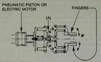
Fig. 18. A pneumatic type gripper may also be electrically operated. In
the latter case the pneumatic piston is replaced with an electric motor. Here
we see a diagram which shows the mechanics of operation of one type gripper.
Notice that the "fingers" open in a rotary movement, not a parallel,
translatory movement.
One interesting aspect of this gripper is the lever arrangement which makes the jaws open and close as the drive mechanism pulls or pushes the levers at point A. A second item of interest in this unit is that the jaws have a soft face which permits some compliance in the grasping action. What this means is that the jaw faces can conform to the shapes of some objects to grasp them better, and are not rigid as would be the case if the jaw faces were solid metal. Also, when you have this compliance capability, it is an easy step to incorporate some pressure activated switches in the complying material such that when the object is grasped a switch is closed that lets the computer know that the object is being held. The computer can then order, perhaps, a slightly in creased tightening of the jaws. Not enough to damage any thing, but enough to insure that the object won't slide out of the gripper when the robot arm moves it. In systems where the jaws simply close to a certain dimension and are stopped, if the size of the object changes or its physical shape changes, then the object may not be properly grasped at all. One has to re-program the closing dimension in order for the gripper to close satisfactorily on the new object's shape or configuration. Compliance is a good thing and we can think of only one possible disadvantage. The material may wear out and have to be replaced.
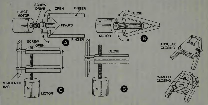
Fig. 19. Some types of grippers, and the operation of an angular closing
type and a parallel closing type.
Examine Fig. 19 where two types of gripper arrangements are shown. Manca, Inc. manufactures various types of grippers for robot machines. Notice that in A two fingers which are pivoted can be caused to move through an angular rotation if they are connected by a suitable screw and nut-type linkage to a motor's gear train shaft. As the motor rotates the shaft screw it will pull or push the linkages to cause them to open or close, as shown in B where the position is closed. The illustration in B of Fig. 19 also shows the disadvantage of this type gripper action. Because the motion is angular the tips of the fingers tend to come together while the body of the finger has a rather wide gap or spacing. Of course, as shown by the dotted lines in B, one might use a compliant material which can compress and this helps to overcome this difficulty.
If we examine further in Fig. 19 we notice that part C will overcome this disadvantage of angular motion because here the electric motor will cause the fingers to come together in a parallel motion instead of the angular motion just described. In part D of the illustration we see how nicely the fingers close together. This may be an ideal method for palletizing, or similar type work for the robot.
Only two fingers have been shown. Please realize that in some cases it may be necessary to use three or more fingers and these can be made a part of a somewhat elaborate mechanical system which can be activated by a motor arrangement without undue difficulty. The principles of operation may be the same as we have herein illustrated. In the pictorial we show two such units courtesy of Manca, Inc. In some applications where a slight opening and closing of the fingers is all that is necessary to grip the object the rotary or angular system might be very satisfactory. Since it closes only slightly, you would not have the finger-tip condition we have shown at B or Fig. 19.
When one has fingers which can move in a parallel manner, it is mandatory that guide rods be used to hold the fingers in line while the motorized section opens or closes them. We have called this part of the gripper a stabilizer bar in Fig. 19.
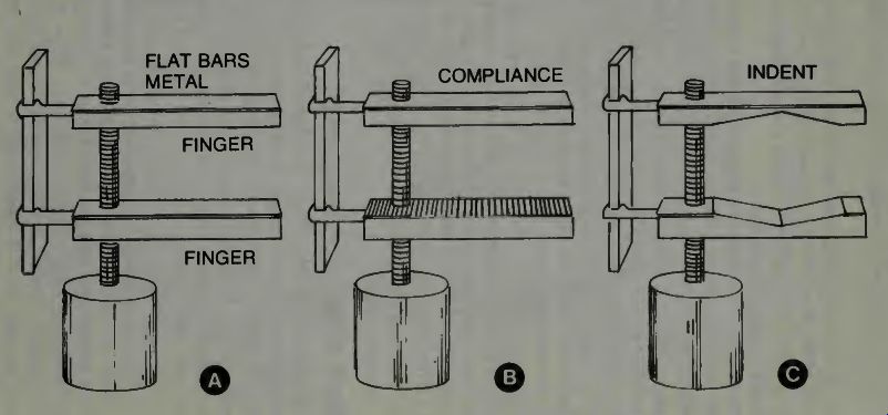
Fig. 20
Now we turn our attention to the fingers portion of the grippers. We use Fig. 20 as an aid to our thinking. The fingers may be just bar-like metal units or they may be flat surfaces of metal. They may have some compliance or sticky material attached to the flat metallic surface as shown in B, or they may have an indent of some particular shape as shown in C. The gripper's fingers will be designed and shaped according to the type objects they are to handle and may include even pneumatic suction cups on the inside edges which will afford a tighter grip or better holding capability on fragile or light weight objects which must be moved. In such a case a very delicate closing of the gripper can be accommodated so that it doesn't close tightly at all. The gripper's fingers will close enough to bring the suction cups against the object and then they will stop moving. The suction of the cups then will hold the object while it is being moved by the robot arm.
Figure 21 is a typical commercial, angular type gripper for an industrial robot. This unit can be operated by a hydraulic system, a pneumatic system, or a spring system.
Notice the limit switch labeled here as a proximity switch.
Realize that with hydraulic or pneumatic systems the backpressure in these systems can cause the proximity switch to activate, sending a signal to the control computer that the jaws have gripped something with a pre-determined force.
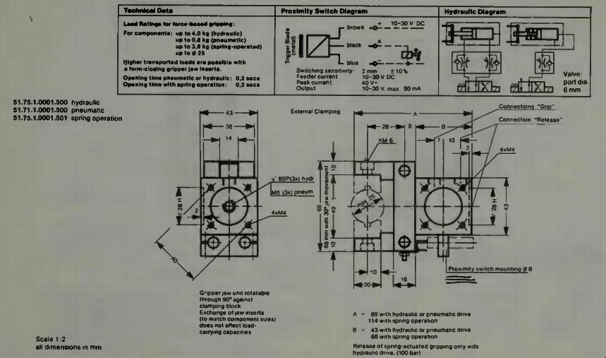
Fig. 21

Fig. 22
In Fig. 22 the specifications are shown for the parallel motion jaws of the Fibro-Manta gripper module. Also shown are the diagram of the hydraulic system and the diagram for the proximity switch installation.
We normally do not think of a gripper as being some unit which must operate within a given time limit, but it is such a unit, especially in industrial applications. If the robot is to be a part of a large automated chain, then it will receive the units it handles in some pre-planned time sequence. In order to do this precisely, the jaws of the gripper must open at a particular instant of time, close in some fraction of time, and open again on schedule. Note the time specification of the unit in Fig. 22. If the unit is operated by hydraulics or pneumatics the time is 0.2 seconds, which is very fast. If the unit is spring activated then the time is longer by 50% to 0.3 seconds. If these jaws were operated by an electric motor the time will vary depending on how they were operated. Using a clutch, gears, or a direct drive motor could vary the time to substantially more than the fraction of a second stated for the hydraulic or pneumatic units.
A COMPARISON OF GRIPPER POWERING UNITS
We can make some comparisons among the three or four types of activation units used to power robot grippers. First let us list four types. Hydraulic uses a non-compressible oil or similar working fluid. Pneumatic uses dry air or similar type gas for operation. If the gas is exhausted into the atmosphere it must not be toxic. Electric uses electric currents and magnetic fields to produce the required forces. Spring is a reactionary device responding to a compressing or expanding force produced by some other means. Like the hammer mechanism of a pistol, the spring can be cocked at a slow rate and then released by some trigger mechanism. When it is released it responds violently, and in a very short span of time it returns to its rest state. A spring may or may not have vibratory tendencies. A spring may come in many shapes and forms and sizes from the commonly visualized circular unit to a simple bar-lever type arrangement. However, it is reactionary, and must be driven to its state of energy storage by some other means. This requirement may or may not be a disadvantage.
HYDRAULIC-ACTIVATED GRIPPERS
The hydraulic system works with a non-compressible fluid. This means that there is no give in the system. It consists of a storage tank a pump or compressed air system to apply pressure to this oil. The piston converts the pressure into mechanical motion. The flow of oil to this piston is regulated by the transfer valve, which is the means by which the robot brain can control the movement of the arm segments. The transfer valve is electrically operated. It consists of a spindle which has large and small sections machined into it. When the large sections cover the oil-flow ports, the oil is shut off. When the small sections are in line with the oil-flow ports, the oil can get by the spindle. The spindle thus must be centered when a neutral signal is applied to the magnetic coil which encompasses the spindle. The centering is usually accomplished with a spring which is factory adjusted. From the description we can assume that the speed of operation of the piston will be governed by the speed of oil flow, and its pressure.
The transfer valve is subject to two forces which can cause some delay in operation. They are stiction and friction, the friction being of a viscous type, while the stiction is a molecular attraction which tends to cause a kind of binding when two metal parts are very closely machined and put together. In other words, a larger force would be required and there would be some delay if the spindle were at rest when the signal to move the spindle energized the magnetic field.
To overcome this problem, it is customary to apply a low frequency ac current to the magnetic winding and this causes the spindle to vibrate at a high frequency with low amplitude.
Since it is thus in constant motion around its neutral position, the stiction force is minimized, and a faster response is obtained. But we must also remember that the working fluid, oil, has a high density, and thus, even though it is light weight, (low SAE number) it also adds delay in motion. Thus, while a hydraulic system is very fast in operation, it does have some delay forces acting on its elements.
We can summarize the hydraulic type gripper, then, by saying that it is very powerful and very fast. It requires some ancillary equipment and it requires high pressure secure lines, fittings, and seals.
THE PNEUMATIC SYSTEM
The air or pneumatic system is operated with compressed air or a gas of similar type. Air is compressible, thus under large back forces the system must apply more pressure to adjust or the system will "give" a little. If the additional pressure is applied and the back force is reduced suddenly, the system must accommodate and adjust, and so we have some tendency toward an oscillatory motion of the output member of the system under these conditions. But air is much less dense than oil and thus can move faster and so the pneumatic system is probably the fastest system possible.
Valves, seals, and the working gas itself must be kept clean and dry which means filters and other ancillary equipment to do this task. The air, or inert gas, may be exhausted into the atmosphere and the storage tank may be supplied from the atmosphere using a pump, so, unless the system works in a vacuum or under water it can get its working fluid from the atmosphere and put it back into the atmosphere after using it! The pneumatic system is fast and has the happy advantage of being usable in reverse, or in a suction capacity. It can hold items and can attract them and be otherwise of value in a robotic system.
Because the air is compressible, it can be stored in tanks where it can be drawn in low amounts for a long time to activate some pistons through a transfer valve system similar to that used in the hydraulic applications. Compressed air can be used to pressurize a hydraulic system, and if the air is contained in tanks, then the hydraulic system can be operated without a pump or storage tank separate from the air-oil supply cylinder. Of course in this arrangement the oil is not returned to the cylinder after use, it must be expended out of the system in some way.
The seals in an air operated system must be tight be cause the density of air is less than oil. A transfer valve used in the air system must also overcome stiction and viscous friction even though the viscosity of the air is very low. Then, as we have stated, the air must be dry (inert gas is often used because of this), and the air must be clean, requiring filters with micron size holes in them.
THE ELECTRICALLY OPERATED GRIPPER
Perhaps the most versatile powering system is electricity. It is easily controlled through well known means, and as we have seen, motors can be mounted directly at the point of usage and screw drives or clutches or cables can be used to transmit the mechanical power. Electric motors are reliable, have long life, can be well sealed, have no leakage problems, require no tight seals and so on.
The motor also has a disadvantage or two. First, in order to get lots of power one must have a powerful motor which means bulk in size, and they are heavy. If one uses a gear train to develop the required power, delays in movement must be expected unless the motor turns at a fantastic speed. The armature is heavy so there is always the inertial overshoot problem to content with, snap-close clutches tend to wear and have to be replaced and cable drive systems can become loose if they do not receive constant attention. All of these problems can be overcome, however, and the advantages make it worth it.
Some advantages of additional importance are that the electric motors can be controlled with either ac or dc electricity. They can develop, through their own back emf, voltages and currents proportional to their speed and these can be read directly for control purposes. This prevents or helps to pre vent overshoot and subsequent oscillation or hunting. Electric stepper motors can be moved precisely with electronic pulses, and a computer can keep track of exactly how much the motor has moved. Solenoid-type magnetic units can cock spring loaded units, which then can be released by another magnetic trigger creating very fast operation.
SUMMARY ON GRIPPER POWERING METHODS
To summarize on the powering system for grippers we might list the pneumatic system as fastest, using compressible gas, requiring excellent filtering and tight seals, and producing a good powering level. It can be used on delicate operations.
The hydraulic system is the most powerful, requires ancillary equipment to pressurize the oil, needs good tight seals and is slightly slower than the pneumatic system.
The electric system is versatile and comes in many forms, is easy to control, but can be bulky and heavy if lots of power is required. It can also be used on delicate operations.
GRIPPER SENSORS
We must not leave this discussion concerning grippers without mentioning the feedback units which can be used with such end-devices. We know that many countries are experimenting with fiber-optic systems built into the gripper to give the control computer some knowledge of the proximity of objects, the shape of objects, and when the gripper has such items in its grasp.
Examine Fig. 23 where the angular type gripper might not be most suitable because the light beams might not constantly impinge on the receptor units in the fingers. In A we see the static condition of a gripper and the light beams from the generators going directly across the open space to the receptors where they cause signals to be sent to the computer. If you will imagine the top finger and bottom finger pivoting as they open to grasp something, you will see how the light beams will be moved toward the end of the finger and no longer impinge perpendicularly on the lower finger receptors. See part B of Fig. 23. You might consider this to be a valuable effect if you let the beams activate the receptors, say 2, 3, 4:and then 3, 4 and then finally, just 4 and let the signals thereby generated inform the computer controller just how far the jaws have opened. Then if the beam is interrupted completely, the computer knows an object has come between the fingers and can initiate closing of them.
If we consider a parallel gripper finger movement such as previously described, then we note that all beams stay positioned on their respective receptors from wide open to close position of the fingers. This fact can be used to let the computer know how far inside the jaws an object has been positioned as well as the fact that it has been positioned therein. This could be of value in some applications.
Some applications might use a gripper-finger system wherein light would be emitted from each finger outward and a receptor near the emitter would then receive a reflection when an object was encountered. This idea could be used to help the gripper find an object on a belt, or help it be re positioned by the computer brain of the robot when items come along some feeder system with some discrepancies in their position. There are many ways in which this type of sensor might be used in a robotic system gripper.
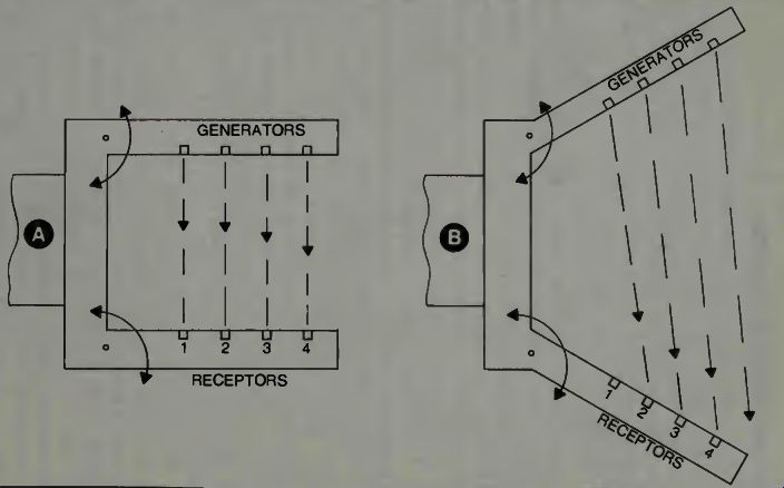
Fig. 23. Fiber-optic sensors systems for grippers.
Another sensor which has been used is the proximity switch system or the back pressure switch system which enables the robot's brain to apply just the right pressure to the fingers to firmly grasp an object once it has found it and has it within its fingers or jaws. We have had some examples of this type switch system in the Mini-Mover-5 system. The back pressure switch outlet is shown on the Fibro-Manta specification drawings, Figs. 21 and 22. We know it is relatively easy to incorporate such a switch in the fingers themselves. It can be closed when a given pressure is applied. These switch sensors are very reliable and very commonly used.
If the objects being handled are metal of a ferro-magnetic type, then one might imagine a gripper made of some non metallic substance and inside this gripper a sensor which can generate a magnetic field which will be routed with more intensity through its windings when ferrous material comes into its field. The closer the object is to the generated magnetic field the stronger the sensor signal would be, thus we have a proximity sensing device with no moving parts. It can be very sensitive and very reliable. There are many ways a magnetic field might be used as a sensor system in a robot's grippers.
POSITION SENSORS FOR GRIPPERS
The type sensors we have discussed have been of a proximity type. They can inform the computer that an object is present, where it is with respect to the grippers jaws, and so on. Now we want to consider some simple type sensors which can inform the computer of the actual physical position of the grippers jaws. Refer to Fig. 24.
At A on the figure we can see a linear potentiometer which has been connected mechanically to the bolt-screw arrangement which translates back and forth to open and close the gripper fingers. At this particular point of the mechanism the motion is a translation and so a linear translatory potentiometer can be used. The translatory potentiometer can be calibrated so that a fraction of a volt represents a fraction of an inch. It will give a signal amplitude directly proportional to the position of the fingers since they move together and in the same opening or closing direction. Notice that only one need be used because of the simultaneous and twin action, of the fingers. If the linear potentiometer is used in a bridge as shown to the right, then opening the fingers will (or can) produce a negative signal with respect to ground, and a closing of the fingers will produce a positive voltage. Now we have both amount of motion and direction specified by an analog voltage.
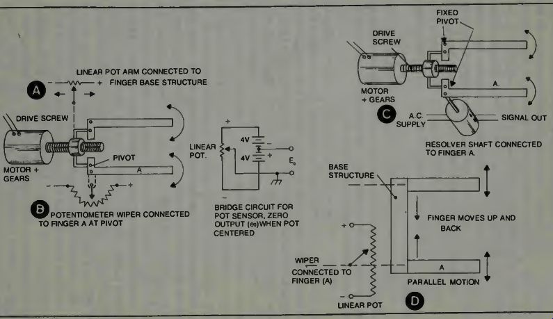
Fig. 24. Position sensors concepts for grippers.
At B on that same section of Fig. 24 we show how a regular circular or semicircular potentiometer might be used in the same manner. The arm of the potentiometer must be fastened to the finger at the pivot point so when the finger rotates about this point it will turn the wiper. The body of the potentiometer must be fixed in place as had to be done for the linear potentiometer. The housing shell or frame on which the fingers are mounted can be used for this purpose. It would work in the same manner as the linear pot.
At C on the figure we see how a resolver might be used to give amplitude and direction information to a computer. It has to be mounted in a similar manner to the circular potentiometer. It has an armature which must rotate with the movement of the finger. The stator part of this unit has to be fixed. When the rotor or armature is turned, an ac signal is produced from this unit which has a phase relationship directly proportional to the displacement. The amplitude of the signal is proportional to the amount the armature has been turned. This is an ac system which is quite commonly used in servomechanisms for position feedback information. Again, note that only one unit is required to give information on the fingers because they move simultaneously, and always in the same direction.
Finally, examine Fig. 24 D which is simply a parallel type gripper equipped with a linear translatory potentiometer to measure and generate signals proportional to the finger and direction. It works the same way A did.
It is possible that one might ask why we need position information on the fingers of a gripper. First because the gripper fingers want to be opened to receive or grasp some thing and the robot's brain will want to know that the fingers have opened to the proper degree. Second, the fingers will want to be closed only a specified amount in some cases to receive specially constructed items. Again the robot's brain wants to know that when it initiates a signal for the fingers to close, they have done so, and to the amount specified. It is much the same as our human requirements to know our hands have our fingers open to pick up something, or that our fingers are pre-positioned to make grasping of special objects easier.
We also like to know when our fingers have opened to release the object, although we are not really conscious that we have obtained this feedback information. Our eyes simply tell us we have put a book on a shelf, replaced a mechanics tool, or laid down a pencil or whatever.
So we have proximity sensors and position sensors. Do we need any others? You might well answer yes without fear of contradiction. If the robot is working in an environment where temperature is a factor on the parts it handles, then, perhaps, it needs a temperature sensor to tell it when it can handle a part and when it cannot handle that part. If a grinding operation is being done then the robotic brain might like to know when the part is reaching a too-high temperature due to the abrasion, and thus pull it away from the grinding wheel.
Temperature sensors in the form of thermocouples are commonly used in automobiles and in our homes on water-heaters and perhaps in other places. They can generate a voltage which can cause a switch to open or close and thus produce the high temperature warning signal. It is possible, also, that the thermocouple can generate voltages proportional to the temperature so one could have gradual control over a heat application process if this was necessary.
What else might we use? How about a vibration sensor? This might let the robotic brain know when some object being handled was not going through its process smoothly for some reason. If the mating of a part is not a good smooth operation then excessive vibration could occur which would be felt. The vibration sensor, in turn, would sense this and send the signal alarm. Here, again, it is an item which is commonly used in the market place. This type sensor is used on large window glass to signal breakage, thus security systems have them, and instructions as to their use, and security people have experience in their use. You wouldn't want such a sensor to be too sensitive as there is always some vibratory action in a mechanical robot.
If you are an engineer or experienced experimenter then perhaps you desire some kind of speed-of-operation or speed-of-motion signal. This signal can be obtained using derivative electronic circuits, into which a part of the position signal is fed. One could also use some kind of small tachometer attached, to moving elements to produce a signal proportional to the speed of movement. Remember that the rate-of change of position is velocity, and so a first derivative circuit whose input is the feedback position signal should produce a signal which is proportional to the velocity of movement.
SUMMARY ON GRIPPER SENSORS
There is no doubt but what a robot's gripper must have some kind of sensing devices built-in, if it is to do expanded and complex tasks. It must also have some kind of compliance so that the gripper can adjust to the shape of the object it handles, especially if the object changes in size and/or shape in various batch units. Grippers must be matched to the task they are involved with, such as high temperatures or very tight gripping.
You may be thinking ahead and wondering just how optics, or the fact that robots can be equipped with eyes, might affect the gripper sensor concept. Giving the robot eyes will assist it, but gripper sensors still may be required.