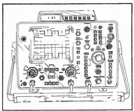
Fig. 10-1 A Hewlett-Packard model 1742A oscilloscope used to troubleshoot microprocessor systems.
| Home | Audio mag. | Stereo Review mag. | High Fidelity mag. | AE/AA mag. |
The troubleshooting philosophy for microprocessor-based devices is generally no different than for any other types of digital systems.
As with any circuit you are trying to analyze or troubleshoot, it is helpful to first become familiar with the circuit. Studying the theory of operation, the block diagrams and the schematic provides a basic understanding from which to work. In this section, problems relating to microprocessor systems and the troubleshooting techniques for dealing with them will be discussed.
A number of testing problems are unique to microprocessor systems. For one thing, most of the control is in the software, so that signal flow is hard to trace. Another difficulty is that everything happens too rapidly to see in real time. In most cases, a microprocessor system, unlike many logic circuits, cannot be stopped and manipulated. Measurements must be taken while the microprocessor is running. Thus to troubleshoot the micros use the oscilloscope, signature analyzer and logic analyzer as these instruments rely on circuit activity for their measurements. A scope such as the HP-model 1742A shown in Fig. 10-1 will help you identify micro system problems.
Microprocessor bus structure poses additional difficulties.
Data on these buses are often unstable or meaningless because of three-state outputs, multiplexing and switching transients. These conditions cause no problems for the system itself, since it is synchronous and knows when the bus lines contain stable signals.
The signature analyzer and the logic analyzer also know when these lines are valid, because of the clock signals provided to them. The scope does not have this capability. It provides little quantitative information, but is useful for examining qualitative factors, such as general activity, logic levels, waveform timing and bus conflicts.
Because bus structures also make it possible for many devices to be connected together on a single node, finding the one bad device on such a node can be difficult. The current tracer is useful for this purpose. The data bus also acts as a digital signal feedback path and tends to propagate errors through good circuits and then back to the fault source. The best way to deal with this problem is to open the feedback path when possible. We will be looking at a few of these techniques.
Complex devices are often connected to the microprocessor buses. It is difficult to test these devices using simple stimulus response testing. The correct operation of these devices can be verified by swapping them with a known good chip, or by observing that the function they perform for the system is being performed correctly.
Fig. 10-1 A Hewlett-Packard model 1742A oscilloscope used to troubleshoot
microprocessor systems.
Microprocessors are sequential machines. Program flow depends on a long sequence of instructions and events. If even a single bit of information is incorrect, the whole system can go awry. Noise glitches and bad memory bits are the most common sources of single-bit errors. Others will also be discussed later. These failures are difficult to pinpoint because the entire system may appear to be operating incorrectly.
CLOCKS
Bad clocks can cause fouled, but running, systems. A number of malfunctions can result in system clocking problems. Clock problems can show up as a failure of the system to function at all (no activity), the ability to function only open-loop (free-running), or semi-functional activity (a meaningless and undefined program sequence). Some microprocessors are sensitive to clock speed.
Because many systems run at spec, even a small variation in clock rate (too fast) can cause system failures. If the system runs too slow, dynamic storage cells on ICs in the system may fail. Both of these problems are more likely to occur when resistor and capacitor (RC) clock circuits are used instead of the more accurate and stable crystal-controlled circuits. However, crystals can sometime break into a third overtone oscillation mode, causing a much higher than expected clock rate. In addition, clock voltage levels are not necessarily TTL compatible, but may be much wider in voltage swing.
Microprocessor clock specs can be found on the device data sheets and can be checked using frequency counters and oscilloscope.
POWER-UP RESET
The power-up reset circuit of the microprocessor can also cause fouled, but running, system operation. A reset pulse that is nonexistent, too short, too noisy or too slow in transition can start everything off at the wrong time, resulting in out-of-sequence, partial, or no reset activity. Problems can also occur in reset circuits that are susceptible to power-supply glitches. Even when Schmitt input circuits are used, slow edges can cause reset timing skew from one device to another within some systems. This will cause some of the devices to power up before the others, resulting in erroneous behavior. A too rapid on-off-on system power sequence will fail to restart many systems. It may then be necessary to increase the off time to allow the power supplies and restart circuits to discharge.
None of these restart failures will necessarily prevent the system from running. It may run for a short time and then stop, lock up in meaningless program loop, or even perform most of its normal operations. The key point to remember is that the system must complete the power-up reset sequence to insure that all of the test, control and initialization operations necessary to bring the system up have been performed.
Power-up reset circuits are normally operative only when the system is initially powered up. They can also be monitored at that time with storage oscilloscopes and logic analyzers. They can also be manually overdriven and controlled externally for testing purposes.
INTERRUPTS
Stuck or noisy interrupt lines can cause faulty system operation. The system may work with a stuck line but it will do so very slowly (spending most of its time servicing the "phantom" interrupt). Noisy interrupt lines can cause sporadic system changes to occur (e.g., a phantom depression). Or peripheral inputs or outputs may occur at improper times. Sometimes the system may not respond at all to certain I/O devices, which may occur when a higher priority interrupt has disabled the lower ones.
Interrupt line activity can be monitored with a logic probe, logic analyzer, or oscilloscope. Interrupts are asynchronous in nature and can be manually controlled (enabled or disabled) for testing purposes.
SIGNAL DEGRADATION
The long parallel bus and control lines present in medium-to large microprocessor systems are sometimes susceptible to crosstalk and transmission line problems on critical lines (such as clocks and enables). These problems can show up as glitches on adjacent signal lines or ringing on the driving line (causing multiple transitions through a logic threshold). Either of these situations can reject faulty data or control signals that are very difficult to detect.
This problem is most common when signal lines are too long and already taxing the timing margins of the system. When extender cards are added to these systems or high-humidity conditions exist, failures may occur. Cross-coupling of lines on extender cards can be a problem when fast signal transition lines (such as Schottky gate outputs) run alongside other signal lines, even when they are on opposite sides of a PC board.
MEMORY SYSTEM CHECKS
Memory failures in microprocessor systems can produce deviant system behavior in a number of ways. Anything from a total system failure to a single faulty bit of stored data can occur. Most memory failures can be found during the power-up self-test program, unless the memory failure prevents this program from running. If the system does not do a RAM verification test and no RAM test service fixtures or procedures are provided, it is nearly impossible to test the RAM. You will probably need to resort to substitution techniques when a RAM becomes suspect.
RAM failures occurring in the area of the memory used for the stack will usually cause the system to crash, even for a single-bit error. Otherwise, RAM failures may cause soft errors that result in unreliable system operation. Faulty dynamic RAM refresh circuitry is another factor to consider in diagnosing apparent RAM failures.
ROMs can also fail. Such failures are more frequent when non-mask programmable types are used. A single bad bit could crash the system. Even worse, 99 percent of it could work and 1 percent could produce erroneous results. ROMs can be effectively tested during power-up self-test, if such tests are designed in. But unlike RAMs, ROMs can also be tested by other techniques if no self-test is provided. One such technique involves free-running the system and then using a signature analyzer to either verify documented signatures or compare the outputs of a suspected ROM with that of a ROM in a known good system. Figure 10-2 shows the H-P Signature analyzer being used in such a check.
USING SELF-TEST PROGRAMS
The programmability of microprocessor-base systems can be used to great advantage for system testing. Programs stored in the ROM of the system can test ROMs, RAMs and the processor itself.
Often the I/O can be tested to some extent. Software can also be used to provide stimulus to an external test instrument, such as an signature analyzer.
ROM TESTING
The most common technique for testing ROMs uses a checksum. When the ROM is programmed, all of its words are added together, ignoring any carries that result. This number is complemented and stored in the last (or sometimes the first) word of the ROM, so that when all the words are added together (including the checksum stored in the last or first byte), the result is zero.
If the total is not zero at the end of the test sequence, then something is wrong with the ROM. Unfortunately, the checksum is not totally reliable. It detects any single-bit errors; however, there are many combinations of two or more errors that still produce the correct checksum. Thus, a ROM that passes a checksum test is probably good. If the test fails, something is definitely wrong, though it might not be the ROM itself.
RAM TESTING
RAMs are tested by writing a pattern into the memory, reading it back and verifying that it is unchanged. Of the many different patterns that can be used, a common one is the checkerboard. In this pattern, all the bits are set to alternating ones and zeros. Once all memory locations have been tested, the pattern is repeated with each bit reversed, verifying that each bit of the RAM can store a one and a zero. Many other patterns used to test RAMs are specifically aimed at detecting various failure mechanisms within the RAM. No memory test can guarantee 100-percent accuracy, even though it may show that each bit can store a one or a zero. RAMs can be pattern sensitive. For example, one location might correctly store 01010101 and 10101010 but fail when 01111000 is stored.
Even for a small RAM, it would take an extremely long time to test every possible pattern sequence. For this reason, RAM test credibility is generally much lower than that of ROMs. As with the checksum test, if a RAM passes the system self-test program, it is probably good. If it fails the test, something is definitely wrong.
MULTIPLEXED I/O
Multiplexed keyboards and displays often share some of the same scanning circuits. In these situations a struck key can appear to make the display fail. Likewise, a bad display driver input could cause a keyboard error. The interaction between common scan circuits must be considered in making diagnosis.
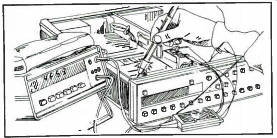
Fig. 10-2. Hewlett-Packard Signature analyzer in action.
INTERFACES
Many microprocessor systems interface with other systems through external communication lines (RS-232C, telephone mod em, etc.). These lines are frequently long and are often exposed to sources of electrical interference, such as relays, transformers, motors and lightning surges. Electromagnetic interference (EM) coming from these sources can cause the transmission of faulty data, overstressing of interface circuits, and with lightning a complete component failure. Generally, output line driver circuits tend to have higher-than-average failure rates, due both to EMI stressing and to the high transition currents that result from driving 'capacitive interfacing cables.
TROUBLESHOOTING TREES
A troubleshooting tree is a graphical means of showing the sequence of tests performed on a product under test. These trees are often drawn as flowcharts in which the results of each test determine what step for repairing microprocessor-based devices can save considerable time and effort.
Shown in Fig. 10-3 is a portion of the troubleshooting tree for a digital voltmeter. Theoretically, it should lead you to the defect by means of actions and decisions taken along the tree. This may not always be the case. A perfect troubleshooting tree must consider all possible failures, a difficult task for the person writing the troubleshooting tree to meet. Also, these trees tend to be fairly generalized, lacking the specifics desired for making tests and decisions. Few troubleshooting trees provide practical information about how a specified test or measurement relates to what the circuit does or is supposed to do. If the troubleshooting tree fails to direct you to the actual fault, you can be left at a dead end. However, the tree will often be your best guide-at least to begin with.
The good tree seldom leads to a dead end and provides a logical, well-directed sequence of tests and measurements, requiring a minimum level of understanding of the circuit under test. Often good trees include advanced techniques such as signature analysis to simplify the procedure. In troubleshooting a device, even the poorer troubleshooting trees can be useful for localizing a failure area in the system and can save time.
Now let's take a look at some general steps that you can take to troubleshoot a microprocessor-based product. Numerous service techniques and "tricks of the trade" are interspersed with the description.
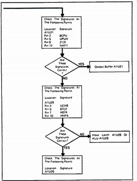
Fig. 10-3. Typical troubleshooting tree.
NOTE THE PROBLEM
It is important to have a general understanding of the defective unit so that you can be sure that a problem really exists. To some degree, you should know what it does and how it operates. Microprocessors allow designers to design systems that are not only complex in function, but sometimes complex to operate as well. Be sure the apparent problem is not a user error, but a real device fault.
Few things are more frustrating than trying to repair something that is not faulty. In some situations, it appears that a device should do something it was not actually designed to do. For example, a DVM AC SELECT switch may work on VOLTS but not on AMPS. This design limitation can usually be verified in the operating manual and does not indicate a product fault, but only a shortcoming.
Design bugs in the firmware (ROM) can sometimes cause failures when used under conditions that were not anticipated during the product design. These are more likely to occur in early production runs and can best be verified (if suspected) by checking with the manufacturer. At the other extreme, a problem may actually exist but not show up because the devise was not properly operated. These kinds of problems are often very simple to detect, but can also be very complex. For example, errors can occur when an unusual sequence of operations is performed. Because the complex problems are much more difficult to test for, extensive test procedures are used to test units at the factory. The customer, bringing in a unit for repair, has no trouble pointing out a problem, but it is up to the technician to solve it.
THE FRONT PANEL
A great deal of diagnostic information can often be obtained without removing the unit from its case. Most microprocessor based systems have a front panel. Usually there are switches, LEDs and indicators plus inputs and outputs. Checking the front panel is a process in which the switches, buttons and other inputs are used to solicit responses from the device that can be observed using its indicators and other outputs. For instance, if the indicators are all dead when the power is turned on, you might suspect a bad switch, fuse, power cord, battery connection or the power supply.
If one segment of a display is out, it is probably the display itself or the driver circuit.
Always take advantage of any designed-in-performance verification or power-up test modes and diagnostic messages that are available. At this point you may have some idea of where the problem is or you may already have the unit repaired. But in all likelihood, neither has taken place.
CHECK THE MANUAL
If all else fails, look at the service information. This poor (but prevalent) attitude makes even less sense for microprocessor based devices than for conventional electronic ones. There may be many tips of service aids and procedures in the manual just waiting for you to check out. Special service switches, jumpers, test devices, indicators and test techniques can make the task much easier.
Try to understand the circuits and figure out where things are.
Check out the theory of operation section, the block diagrams and the schematics. You don't have to do this in great detail but just enough to have some idea of what is going on. Identify the microprocessor, ROM, RAM, I/O, address-decoder, clock, bus, control and interrupt portions of the system.
The life of an IC is generally a sequence of predictable events.
It is born in the IC plant and is shipped to a product manufacturer.
There it is inserted into a circuit board, which in turn is inserted into the finished product. Then the product goes into service, and the IC remains there for the rest of its useful life. Needless to say, not all ICs live a long and good life.
TYPES OF FAILURES
Common fault sources and the best troubleshooting techniques for finding them depend on the history of the product and the environment in which it is tested. When a new product is first turned on at the plant, almost anything could be wrong. Products that fail in the field have all worked at one time. Assembly errors, such as wrong components and mis-wired circuits, usually need not be considered in the field. Also, the likelihood of solder shorts and multiple faults in much greater on the production line than out in the field. Actual in-service failures are usually caused by components or connections that have failed.
CHECKING THE EASY THINGS FIRST
It makes good sense to look at the items that can be tested and repaired easily. The simple things are as likely to fail as the more complicated ones. A case in point is the power supply: It is actually one of the more failure-prone portions of most electronic systems.
It is also one of the easiest to test and troubleshoot. Out-of-spec voltages can cause erratic circuit performance. If the voltage is not checked first, it could take considerable time to pinpoint the problem. A mechanical inspection can also be fruitful. Poor PC board and cable connections, broken wires and loose parts can usually be found either visually or by touch.
COMMON PRODUCTION-LINE TROUBLESHOOTING PROBLEMS
A number of common sources of failure in a manufacturing environment can be found through careful visual inspection of circuit assemblies. It is easy to check for improperly set switches and jumpers, wrong components or right ones put in backward, and cold solder joints. Backward resistor packs can be tough to locate electrically because they can cause interaction between unrelated logic nodes, but they are easy to check visually.
Two of the more common failures in production are solder and gold or copper shorts on printed circuit boards. These can usually be removed with a sharp knife. When the precise place of the short is not known, there is a rather novel technique for removing it that often works. The procedure involves charging a 100,000 uF (or larger) capacitor to 5 volts, as this would be safe for logic circuits.
Then, with the cables solidly connected to the two shorted nodes and proper polarity observed, discharge the capacitor into them and listen for a snapping sound on the board. Check continuity to see if the short has been opened and, if not, try again. This technique should be used with caution since it will open the weakest link of the current path, which may not be the circuit short, but a fine-trace PC pattern.
A relatively new problem in production is the occurrence of bent IC pins caused by automatic component insertion machines.
This can result in an open electrical connection between the IC and the PC board, an intermittent connection, or shorts to traces near or under the IC. The bent pin is often difficult to spot visually because it may look as though it is properly soldered in place. The best way to tell this is to look at the bottom of the board for the ends of any IC pins or along the plane of the board to see under the ICs.
PC board edge connectors are commonly used. They may cause problems in production when their borders are cut off center or when they are accidently covered with solder resist or board sealing spray. Visual inspection can reveal such problems.
Wire-wrap boards are prone to bent posts that can cause shorting. Other common production problems include 14-pin ICs placed in the wrong end of a 16-pin socket, mis-wiring, wire shorts between pins and signal coupling (crosstalk) due to closely bundled wires.
Visual inspection of a device that fails in the field can reveal such things as loose wires, broken traces and dirty connectors. A tap on the right spot of the cabinet can be used to detect loose or intermittent connections and stuck relays. Stressing boards and connectors (by twisting and flexing) can often help to locate some of these problems. You might suspect the PC board edge connectors when a unit is dead on arrival. You may want to try reseating all of the assemblies and circuit board connections to determine whether the problem is poor connector contact. A pencil eraser is useful for cleaning dirty edge connectors.
BOARD SWAPPING
If any of the PC boards are easy to remove and replace with known good ones, you can try swapping them. Boards may also be swapped out of the same type equipment for a quick test. The risk in board swapping is that you could damage a good board because of the same electrical overload that damaged the defective one when it was installed. In any case, power to the unit should be turned off when removing or installing boards or assemblies.
If an identical product is available, functional comparisons can sometimes be informative. This comparison can be especially useful in situations in which it is not clear that there is actually a hardware problem (it may be a product idiosyncrasy or design limitation). If a device in a socket is suspect, try tapping it first to see if there is a loose connection and then try subbing in a known good one. Note, however, that one of the last devices you should suspect, but is most often replaced first, is the microprocessor chip.
The actual failure test rate for these chips is very low. However, because they are complex and their correct operation is difficult to verify, they are often replaced right from the start. This usually applies to the LSI chips used with the micros.
STRESS TESTING TECHNIQUE
A technique called stress testing can be very effective in dealing with marginal or intermittent failures. Stress testing can often cause these types of faults to temporarily improve or become worse, thus helping in pinpointing the fault. Boards are stressed physically by tapping or twisting them, thermally by heat (heat gun) or by cooling them (freeze spray) and electrically by varying the supply voltage. Thermal stressing can be used to isolate a fault in a specific device on a board very precisely because heat or cold can be applied to a single suspected component. Intermittents can result from marginal chips, lead bonds, solder joints, connections and drive and timing circuits.
Briefly touching each device on a circuit board can pinpoint a component that is operating too hot. When a particular device runs a good-bit hotter than others of the same type, a problem may exist.
A faulty device can sometimes be hot enough to burn your finger, so use this technique with caution. Best to use a temperature probe for these checks. Be aware also that some good components may run hotter than you expect during normal operation, and that the temperatures may vary widely from one device to another.
POWER SUPPLY SHORTS
There are some effective ways of dealing with shorts across the power supply. The first thing to do in a multi-board system is to try to localize the short on a single board. This can be done by removing one board at a time until the short disappears, which indicates the shorted one.
One technique for finding the short on a faulty board is to inject current through the two shorted lines with the logic pulser while the power is off. The current tracer is then used to follow this current to the short. Keep in mind that capacitors, especially electrolytics, will have some current going into them because of the pulsing current.
Shorted capacitors can be found by using the current tracer to compare the current levels going into identical capacitors on the same board. The capacitor that shows a much higher level than the others is likely to be shorted. This technique is particularly useful for finding shorted ceramic bypass capacitors.
Another technique for locating power bus shorts is to feed a relatively high current (about 3 to 5 amps) into the short. Be sure to maintain the same voltage polarity and not to exceed the supply voltage normally present. The current path to the short can often be determined by using a DVM with a high resolution (0.01 mV) to look at voltage drops on the power bus traces. Voltages are developed across the traces that are in the path going to the short, and not anywhere else. Refer to Fig. 10-4.
A less scientific, but much more dramatic, technique for finding power bus shorts is to freeze the entire board, allow moisture to condense on it and then power it up with a 3 to 5 amp supply. As it warms up and defrosts, the current path becomes visible and, in many cases, will pinpoint the location of the short.
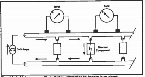
Fig. 10-4. Using a sensitive digital voltmeter to locate bus short.
HOW TO ISOLATE THE FAULT
Once the easy things have been tried unsuccessfully, it is time to get down to the "nitty gritty." At this point, individual troubleshooting skills, intuition and knowledge of the product can really make the difference.
First, be sure to take advantage of any designed-in and documented circuit isolation features, such as selected board removal, service jumpers and special test modes and procedures. It can be very useful to separate the microprocessor system from the peripheral circuits to allow you to diagnose each portion independently.
An important troubleshooting concept is half-splitting. Al though the term may be new to you, you have been using the process for many years. It is also known as divide and conquer. This technique involves choosing a point roughly in the middle of the circuit. It is just as likely that a fault exists before as after this midpoint. If the performance is correct up to that point, the problem will be after the midpoint. This process works best in circuits that have clear, unidirectional signal paths without large feedback loops.
Even with microprocessor-based systems, this approach can be effective because the circuits outside the microprocessor portion often fit these guidelines.
DIGITAL FAILURE MODES
When suspicion falls on the digital portion, the first thing to look for is signal activity. With a logic probe you can examine activity of the clock signals, bus lines, chip enables and control lines. Absence of activity on any of these nodes indicates a possible problem.
The most common failure modes for digital ICs is open lead bonds inside the package. These are thin wires connecting the package pins to the IC chip. If an output lead bond opens, the output pin floats and the logic probe will probably indicate a constant floating logic level because of other device inputs connected to the node. If an input lead bond opens, one or more of the IC outputs will usually appear to malfunction (stuck high, low, or executing its logic function incorrectly). If any of these outputs goes to a three-state bus, it can cause bus conflicts (more than one output at a time), and the current tracer can be used to find these'. Bus conflicts are often observed on an oscilloscope by the presence of bad, but solid, logic levels on the bus lines. However, as shown in Fig. 10-5, the scope provides no information as to the source of the fault. Good bus lines can appear to have solid, bad levels present when all devices on the bus are off.
Another common digital IC failure is a shorted input pin to ground. This fault is often caused by a bad input protection diode on the chip. It usually appears as a stuck low level, which can be seen with the logic probe. An oscilloscope connected to a node with this type of problem shows a voltage level near ground being pulled up, perhaps a few hundred millivolts, whenever a logic 1 output on that node turns on (See Fig. 10-6). The current tracer provides an excellent means of pinpointing shorted input pins. If a current tracer is not available, another means for locating stuck inputs and outputs involves the use of a sensitive (high resolution) DVM and a can of freeze spray. Connect the DVM to the stuck node and select the most sensitive DC voltage range available. Then, while monitoring the voltage, spray each IC connected to the stuck node-one at a time-to change its temperature. Any noticeable change in voltage (more than 10 mV) on the node indicates that the IC being sprayed is drawing current.
A heat source can be used in the same way. This technique relies on the properties of the semiconductor used in the IC that relates voltage to temperature.
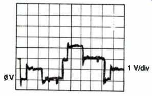
Fig. 10-5. Bus conflicts cause bad, but solid, logic levels.
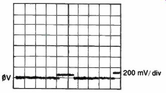
Fig. 10-6. A shorted diode on a gate input clamps the node to ground.
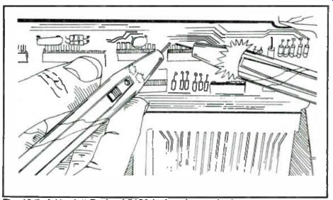
Fig. 10-7. A Hewlett-Packard 546A logic pulser probe in use.
ISOLATION TECHNIQUES
Once a particular input or output pin is suspected, it is useful to isolate it from the rest of the circuit. A quick, nondestructive way to do so is to suck the solder away from the area between the pins and the PC board pad, using a vacuum desoldering tool or solder wicking braid. Then bend the pin so that it is centered in the hole of the pad, not touching at any point. Use a continuity tester to verify that the pin is no longer in electrical contact with the board.
An extender board with switches on bus and signal lines can be used to break selected signals between a PC board and the rest of the system. In this manner, feedback paths and stuck buses can be removed from the main system. An even simpler way to open selected signals going through a board edge connector is to place a piece of tape on the PC board edge fingers that you wish to isolate.
A somewhat unconventional, but often effective means of detecting bus line problems, is to measure the resistance to ground (with the power off) of each of the lines in a particular bus. The resistance of each of these lines is usually the same. If any differs substantially, you may suspect a problem on this line. If two lines show the same (lower) resistance, the two lines may be shorted together. In either case, check the diagram to see if the arrangement of circuits connected to these lines could explain the difference before going any further.
Overriding interrupt lines and chip enable pins on suspected devices can be used to verify that the IC is functioning correctly.
This can be done by momentarily shorting the appropriate pin high or low, or by using a logic pulser. A logic pulser probe is shown being used in Fig. 10-7.
FEEDBACK LOOPS
Digital feedback loops are often difficult to troubleshoot because errors propagate around and around. A feedback loop with a faulty output signal sends this signal back to the input to produce more bad outputs. Opening this feedback path prevents the faulty output signals from going back to the input. Then, if controlled inputs to the loop can be generated, the signal flow from the input to the output can be observed. Often, however, it is not easy to provide this input (many lines may need to be controlled). It may also be difficult to predict correct circuit operation. If another working device or board of the same circuitry is available, it is sometimes practical to allow the output of the good circuit to control the inputs of both circuits. In this manner, you know that the circuit under test is getting the correct input signal. It is then a matter of comparing the nodes of the two circuits and looking for any differences.
CONCLUSION
No amount of knowledge and experience can totally compensate for inadequate service data and information. In some cases, shotgunning (replacing components until the problem is solved) may be the best way out. However, as shown in Fig. 10-8, this is not always a practical solution. Most microprocessor-based products do not fall into this class. Future products will probably incorporate advanced service techniques, such as signature analysis, as more designers realize that the old troubleshooting methods and tools used for random logic are not very effective in dealing with microprocessors.
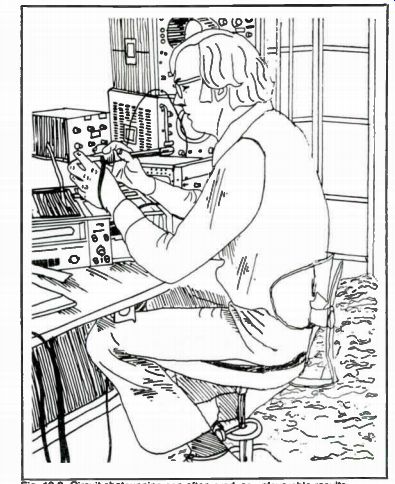
Fig. 10-8. Circuit shotgunning can often produce unfavorable results.
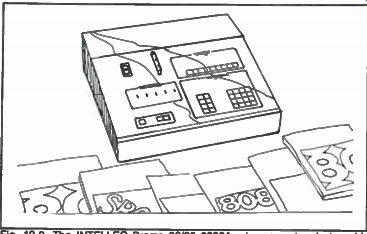
Fig. 10-9. The INTELLEC Promp 80/85 8080A microcomputer design aid (courtesy
of INTEL).
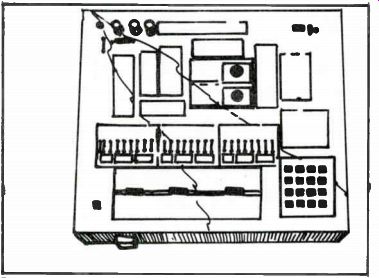
Fig. 10-10. E & L Instruments model MMD-1 microcomputer designer system.
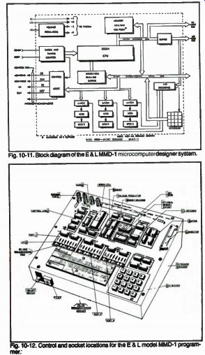
Fig. 10-11. Block diagram of the E & L MMD-1 microcomputer designer system.
Fig. 10-12. Control and socket locations for the E & L model MMD-1 programmer.
Microprocessor systems can be thought of as an extension of traditional digital logic. Many of the components, circuit designs, and troubleshooting tools and techniques are the same. However, there are some differences. Microprocessor systems are bus structured, and many of the devices on the bus are complex LSI ICs. The signal activity between the devices on the buses is constant and complex. It is often useful to break the data bus, which is the main feedback path of the system, to help isolate a fault that causes the entire system to malfunction.
Although troubleshooting trees provide an orderly approach for locating system faults, they are not always adequate. There are numerous techniques, procedures, and tricks that can be effective in diagnosing, isolating and locating faults in microprocessor-based products. Many of these were discussed in this section and all you need-do is put them into action.
The INTEL Promp 80 shown in Fig. 10-9 is a low-cost, fully assembled microcomputer design aid. This device simplifies programming of the system 80 microcomputers, 8080A processors and I/O devices. The 8080A programs can be entered and debugged with calculator-like ease on the large, informative display and keyboard panel.
Figure 10-10 shows the E & L Instruments model MMD-1 mini-microcomputer designer that lets you easily program the 8080A microprocessor chip. A block diagram of the MMD-1 programmer system is shown in Fig. 10-11. Controls and component locations on the MMD-1 are shown in Fig. 10-12.
-------------------