AMAZON multi-meters discounts AMAZON oscilloscope discounts
In electronics there are seven basic units to measure quantities which define what is going on in a circuit. These are (together with the letter symbols used as abbreviations):
Volts (V)-a measure of the potential, emf (electromotive force), or voltage in a circuit. For practical purposes, potential difference, emf and voltage all really mean the same thing.
Amps (A)-a measure of the current flowing in a circuit.
Watts (W)-a measure of the power developed by the flow of current through a circuit.
The other four refer to the effect of components in the circuit, viz:
Ohms (ohm)-a measure of the resistance or individual resistances in a circuit when the current flow is direct (dc).
Impedance (Z)-a measure of the effective resistance or individual resistances in a circuit when the current flow is alternating (ac).
Farads (F) -a measure of the capacitor present in a circuit or produced by individual components, i.e., capacitors.
Henrys (H)-a measure of the inductance present in a circuit or produced by individual components such as coils.
Reactance (X)-the combined effect of inductance and capacitance in an ac circuit.
Capital letters are also used as abbreviations for voltage and current.
Strictly speaking E (for emf) is the correct symbol for a voltage source, with V (for volts) in other parts of the circuit. Vs can be used instead of E for a source voltage. The capital letter I is used for current. In some circuits lowercase letters are used to indicate voltages and currents flowing in different parts of a circuit, e.g., v and i, respectively. These may have a reference annotation attached, particularly in the case of transistor circuits, e.g., ve, describing emitter voltage.
The relationship between units is explained in Section 3. There are also various other units employed in electronics, the use and meaning of which will be made clear in appropriate sections.
In practical circuits, numerical values of these units may be very large, or very small. Resistance values, for example, may run to millions of ohms.
Capacitor values may be in millionths or even million-millionths of a farad.
To avoid writing out such values in full, prefixes are used to designate the number associated with the particular value involved. Again the symbol rather than the full prefix is normally used:
mega (M)-meaning times 1,000,000 kilo (k)-meaning times
1,000 milli (m)-meaning divided by 1,000 (or 1/1,000th) mikro (µ)-meaning divided by 1,000,000 (or 1/1, 000,000th) nano (n)-meaning divided by 1,000,000,000 (or 1/1, 000,000,000th) pica (p)-meaning divided by 1,000,000,000,000 (or 1/1, 000, 000, 000, 000) For example, instead of writing out 22,000,000 ohms in full, this would be shown as 22 M-ohms, or, more usually 22 M-ohm, using symbols both for the prefix and basic unit. Similarly a capacitor value of 0.000,000,000,220 farads would be shown as 220 pica F, or, more usually 220 pF.
The multipliers (M and k) are most commonly associated with values of resistors, and also for specifying radio frequencies. The lowest divisor (m) is most usually associated with the values of current typical of transistor circuits, etc. It is also used to specify most practical values of inductances.
The larger divisors (12, n and p) are most commonly associated with capacitor values.
Single capital letter abbreviations are also used for components. The main ones are:
C -for capacitors
D -for diodes (also sometimes CR)
L -for coils R -for resistors
These are all standard and universally accepted abbreviations. With other components this is not always the case. Thus transistors may be designed T, TR, Tr, VT or even Q on circuits originating from different sources. The use of TR, Tr, or Q is preferred, leaving the letter T as the abbreviation for transformers. Note the abbreviation FET (or fet) is used for a field-effect transistor in text although it may be "Q" in diagrams.
In practical circuits, more than one of the same type of components are normally used. Individual components of the same type are then designated by numbers (usually reading from left to right across the circuit) associated with the component symbol (Fig. 1-1) (see also Section 3). Thus resistors would be designated R1, R2, R3; capacitors C1, C2, C3, . . . and so on.
There is no correct or specific sequence in which such numbers are allocated. They are there only to identify a particular component.
or --i-VSAAr-- fixed value resistor
-II- -A-- -0i capacitor electrolytic capacitor
-10 OS /- -14 coil diode
- or -Vy4- variable resistor (potentiometer) variable trimmer capacitor; capacitor loudspeaker earth battery
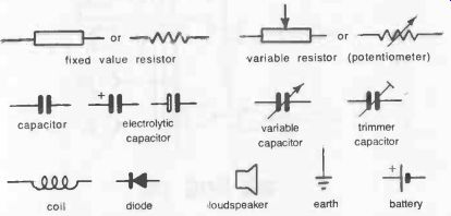
Fig. 1-1. Symbols for basic circuit components. Other symbols are given in
later sections.
Here are some other general abbreviations which are widely used, although again they may be shown in various different ways--capital letters, or lowercase letters in upright or italic, with or without periods. Thus the abbreviation of alternating current may appear in five different ways:
AC a.c. a.c. ac ac
The general preference is that all such abbreviations should be in lower case without periods, and so the following abbreviations are shown that way:
ac -alternating current of-audio frequency agc-automatic gain control am*-amplitude modulated (or amplitude modulation) dc-direct current eht -extra high tension fm*-frequency modulated (or frequency modulation); hf -high frequency; ht-high tension; ic-integrated circuits; if-intermediate frequency (also i-f) if-low frequency;
rf- radio frequency; uhf -ultra high frequency; vhf-very high frequency;
*There is a good reason for retaining capital letters for these abbreviations as AM and FM radios are widely quoted in this way.