AMAZON multi-meters discounts AMAZON oscilloscope discounts
A basic direct current (dc) circuit is simple enough to understand.
A source of electrical force (such as a battery) is connected via wires to various components with a return path to the source. Current then circulates through the circuit in a particular direction. Figure 2-1 shows a very elementary circuit of this type where a battery is connected to a dc electric motor and is compared with a similar closed loop hydraulic motor in a simple recirculating system.
It is obvious what happens in the hydraulic circuit. The pump is a source of pressurized water which impinges on the vanes of the hydraulic motor to drive it. There is a flow of water around the system. At the same time there will be some loss of pressure energy due to friction of the water flowing through the pipes and the motor. This is the resistance in the circuit. But most of the pressure energy delivered by the pump is converted into power by the hydraulic motor.
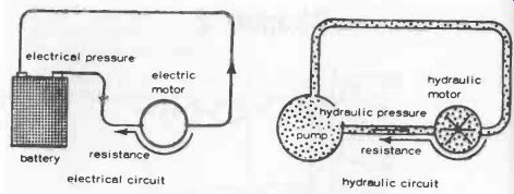
Fig. 2-1. An electrical circuit is similar to a hydraulic circuit.
In the electrical circuit counterpart, the battery is a source of electrical pressure (which in simple terms we designate voltage). This forces an electrical current to flow through the circuit, opposed by the resistance offered by the wiring and the electric motor coils. Again, most of the original electrical energy in the battery is converted into power by the electric motor. Provided the battery voltage does not change, a constant value of an -rent will flow through the circuit always in the same direction, and the electric motor will continue to run at a constant speed.
Conventionally, dc current flow is regarded as being from "positive" to "negative" of a battery or any other dc source (such as a dynamo). It is a stream flow, just like the water flow in the hydraulic circuit, but the stream Is actually composed of sub-atomic particles or electrons. Unfortunately, after convention had established the "positive to negative" flow definition, it was found that this electron stream flow was actually from negative to positive. This does not matter for most practical purposes, but for an understanding of how transistors and other solid-state devices work it is necessary to appreciate this "reverse" working.
"Positive" always seems stronger than "negative," so it is difficult to think of current as flowing other than from positive to negative. We can relate this to electrons flowing from negative to positive by thinking of electrons as particles of negative electricity.
Being "weaker" (negative), they represent a "reverse flow," setting up conditions for a positive flow of current-from positive to negative. Otherwise, simply forget the difference and work on the practical fact that + and - are only terms of convenience used to ensure that components in a circuit which have positive and negative sides are connected up correctly. This applies mainly to batteries, transistors, diodes, and electrolytic capacitors.
All materials are composed of atoms in which there is a stable balance of positive and negative charges (except in the atoms of radioactive elements). The application of an electrical pressure will cause electrons to be displaced from the atom, leaving it with an effective positive charge. It is then in a state to attract any stray electrons. Since there is electrical pressure present, this means that there will be a movement of electrons along the chain of atoms comprising the wiring and component(s) in the complete return circuit. It is this movement that constitutes the electric current flowing through the circuit, the strength of the current being dependent on the number of electrons passing any particular point in the circuit in a given time. Break the circuit and the pressure is broken, so current flow ceases. So, in fact, the analogy with a hydraulic circuit is not really valid in this instance (the hydraulic pump will still deliver water under pressure if its circuit is broken until it has emptied the fluid in the circuit between the break and the pump).
Atoms of materials like metals will give up electrons readily when subject to electrical pressure, and so make good conductors of electricity.
Atoms of most non-metals, including plastics, are reluctant to give up electrons even under high electrical pressure, and so are essentially non-conductors.
If extremely resistant to giving up atoms, they are classified as insulators.
Summarizing, then, a dc circuit when connected or switched on provides a constant flow of current in one direction through the circuit as in Fig. 2-2, unless something changes in the circuit (e.g., source voltage changes, or a circuit resistance value alters). The value of this current is determined by the source voltage and the total resistance in the circuit (see Section 3).
Current flow is also regarded as positive (or positive current).
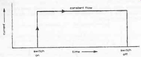
Fig. 2-2. Direct current flow with constant circuit resistance.
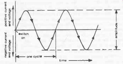
Fig. 2-3. Alternating current flow is in "cycles" of positive and
negative current.
In the case of an ac circuit, the source of electrical pressure continually reverses in a periodic manner. This means that current flows through the circuit first in one direction (positive) and then the other (negative). In other words, a simple graph of current flow with time will look like Fig. 2-3.
The swing from maximum positive to maximum negative is known as the amplitude of the ac current. Also one complete period from zero to maximum positive, back to zero, down to maximum negative and back to zero again is known as a cycle. These cycles may occur at varying rates from a few times a second to millions of times a second and define the frequency of the ac current, frequency being equal to the number of cycles per second. In the case of the domestic mains supply (in Britain), for example, the frequency is 50 cycles -per -second, or 60 cycles-per-second in the U.S. But "cycles -per-second" is an obsolete term. It is now called hertz (abbreviated Hz). Thus standard mains frequency is 50 or 60 Hz.
Apart from the fact that ac is continually swinging from positive to negative current flow, the other difference compared with dc is that the actual current value present is also changing all the time. It does, however, have an "average" value which can be defined in various ways. The usual one is the Root Mean Square (or rms), which is equal to 0.7071 times the maximum cycle values for sine wave ac such as normally generated by an alternator, Fig. 2-4. Alternating current may, however, be generated with other types of waveform.
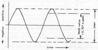
Fig. 2-4. Peak and Root Mean Square (rms) values of amplitude defined and
compared.
Another characteristic of ac is that both the voltage and current are continually changing in similar cycles. Only rarely, however, will the voltage and current both attain maximum and zero values at exactly the same time. In other words the current (waveform) curve is displaced relative to the voltage (waveform) curve, Fig. 2-5. This displacement is known as a phase difference. It is normally expressed in terms of the ratio of the actual displacement to a full cycle length on the zero line, multiplied by 360 (since a full cycle represents 360 degrees of ac working). This is called the phase angle. Usually the current will "peak" after the voltage (i.e., be displaced to the right of the diagram), whereupon the current is said to be lagging and the phase angle is referred to as angle of lag.
The use of the term "angle" can be a bit confusing at first. It is really a matter of mathematical convenience, useful in more complicated calculations involving vector diagrams. For a general understanding of ac it is better to think of angle as meaning a particular "number point" on a line length representing one full cycle divided into 360 divisions. Thus a phase angle of 30 degrees can be understood as a point 30 Beta 60ths along that line.
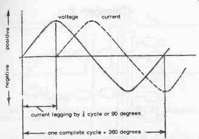
Fig. 2-5. Current usually "lags" behind voltage in an alternating
current circuit.
Phase difference (phase angle) can be an important factor in the design and working of many alternating current circuits because when a current "lags" (or "leads") the voltage, the timing aspects of a circuit are affected.