AMAZON multi-meters discounts AMAZON oscilloscope discounts
The neon lamp is a glow lamp consisting of a glass envelope fitted with two separated electrodes and filled with an inert gas (neon or argon). If connected to a low voltage, the resistance is so high that the neon provides virtually an open circuit, but, if the voltage is increased, there comes a point where the gas ionizes and becomes highly conductive, as well as giving off a glowing light located on the negative electrode. If the gas is neon, the glow is orange in color. Argon is sometimes used as the gas, in which case the glow is blue.
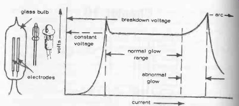
Fig. 10-1. Typical neon lamp construction and characteristic performance.
A neon lamp only works in a dc circuit.
The characteristic performance of a neon lamp is shown in Fig. 10-1. The voltage at which the neon starts to glow is called the initial breakdown voltage. Once this has been reached and the bulb triggered into "firing" (glowing), the voltage drop across the lamp will remain virtually constant regardless of any increase in current in the circuit. At the same time, the area of glow will increase with increasing current, up to the point where the entire surface of the negative electrode is covered by glow. Any further increase in current will then push the neon into an arc condition, where the glow changes to a blue-white point of light on the negative electrode and results in rapid destruction of the lamp.
To operate a neon lamp successfully, therefore, it is necessary to have enough voltage for the neon to "fire," and, after that, enough resistance in the circuit to limit the current to that which will ensure that the lamp remains operating in the normal glow region. Because the resistance of the neon itself is very low after firing, this requires the use of a resistor in series with the lamp, known as a ballast resistor. Typically the firing, or breakdown, voltage may be anything from about 60 to 100 volts (or in some cases even higher). The continuous current rating is quite low, usually between 0.1 and 10 milliamps. The series resistor value is chosen accordingly, related to the voltage of the supply to which the neon will be connected. In the case of neon lamps to be operated off a 250 volt (mains) supply, a 220 k-ohm resistor is normally adequate, see Fig. 10-2. With some commercial lamps, the resistor may actually be built into the body o the assembly.
Lacking any specific information on this subject, it can be assumed that a neon lamp will have no resistance when glowing, but will drop 80 volts. A suitable value for a ballast resistor can be calculated on this basis related to the actual voltage of the supply to be used, and assuming a "safe" current of, say 0.2 milliamps, for example.
For 250-volt supply, resistor has to drop 250 - 80 = 170 volts.
Current through resistor and neon (in series) is to be 0.2 mA.
Therefore:
Resistance = volts amps 170
0.2 x 1/1000 = 850 k ohms, or say 1 megohm.
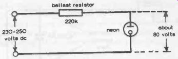
Fig. 10-2.
In a practical circuit, a neon lamp is always connected in series with a ballast resistor to limit current flow.
This should be playing safe with most commercial lamps. If the glow is not very bright, the value of the ballast resistor can be decreased to operate lamp farther along the normal glow region. However, the resistance should never be decreased so much that the whole of the negative electrode is covered by glow as this will indicate that the lamp is becoming overloaded and approaching the arc condition.
Another point about the strength of the glow light is that it will normally appear brighter in light than in dark. In fact, in complete darkness the glow may be erratic and/or require a higher breakdown voltage to start it. Some lamps have a minute trace of radioactive gas added to the inert gas to stimulate ionization, then this particular effect will not be noticeable.
Because of the constant-voltage characteristics of a neon lamp under normal glow conditions, it can be used as a voltage stabilizing device. Thus, in the circuit shown in Fig. 10-2, the output tapped from each side of the lamp will be a source of constant voltage as long as the lamp remains working in the normal glow region.
This voltage will be the same as the nominal breakdown voltage of the lamp.
The use of a neon lamp as a flasher in a relaxation oscillator circuit has already been described (Fig. 6-3, Section 6).
A variation on this is shown in Fig. 10-3, using a 1 megohm potentiometer as the ballast resistor and two 45-volt or four 22 1/2-volt dry batteries as the source of supply. The potentiometer is adjusted until the lamp lights.
The control is then turned the other way until the lamp just goes out. Leaving the potentiometer in this position, the lamp should then flash at regular intervals determined by the value of the capacitor.
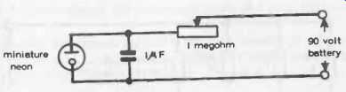
Fig. 10-3. Adjustable rate flasher circuit.
An adaption of this circuit is shown in Fig. 10-4, where the circuit is switched by a Morse key. Phones can be connected across the point shown to listen into the Morse signals, which are also visible as a flashing light. An ordinary bulb would work just as well as a visible indicator (and with a much lower voltage required), but in this case the signals would only be heard as clicks. With the neon circuit, the actual oscillation of the relaxation oscillator is heard. The time constant of the circuit is governed by the value of the capacitor and the setting of the ballast potentiometer.
A further extension of the use of a neon lamp as an oscillator in a relaxation oscillator circuit is shown in Fig. 10-5. This is a true signal generator circuit, the output of which should be audible in headphones or even a small loudspeaker, with the tone adjustable by the potentiometer.
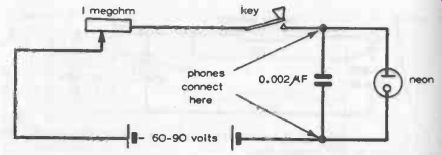
Fig. 10-4. Morse code flasher circuit.
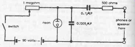
Fig. 10-5. Simple tone generator based on an NE -2 miniature neon lamp.
Neon flashers can be made to work in random fashion (again see Section 6), or sequentially. A circuit for a sequential flasher is shown in Fig. 10-6. More stages can be added to this circuit, if desired, taking the connection of C3 to the last stage.
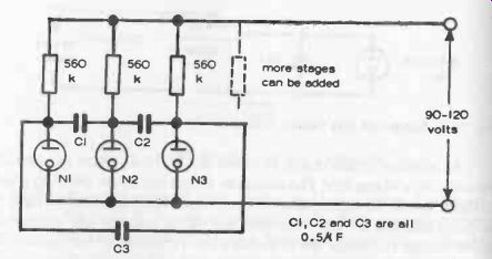
Fig. 10-6. Sequential flasher using NE -2 miniature neon lamps (or equivalent).
Finally, an astable multivibrator circuit is shown in Fig. 10-7, using two lamps. These will flash on and off in sequence at a rate determined by R1 and R2 (which should be equal in value) and C1.
As a general guide to flasher timing, increasing the value of the ballast resistor or the capacitor in the relaxation oscillator circuit will slow the rate of flashing; and vice versa. To preserve the life of a typical lamp, however, the value of ballast resistor used should not be less than about 100 k ohms; arid best results in simple relaxation oscillator circuits will usually be achieved by keeping the capacitor value below 1 microfarad.
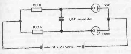
Fig. 10-7. Astable multivibrator circuit, each neon flashing in turn.
LEDs
LED is short for Light -Emitting Diode.
This is essentially a two element semiconductor device where the energy produced by conduction in a specific direction is radiated as light, the intensity of light being governed by the current flowing through the diode. In these respects, they are somewhat similar to neon lamps, but they light at very much lower forward voltages (typically 1.6 to 2 volts) and can generally draw higher forward currents without burning out (typically 20 mA). Originally the color of light emitted by LEDs was red, but now orange, yellow and green LEDs are also available.
Again like neon lamps, an LED is invariably associated with a ballast resistor in series to limit the voltage applied to the LED and the current flowing through it. The value of resistor required is:
R=
Vs -Vf If
Where… Vs = dc supply voltage
Vf = rated forward voltage of the LED
If = rated forward current of the LED at specified for ward voltage.
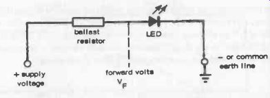
Fig. 10-8. LEDs are connected with a ballast resistor in series to drop the
supply voltage to the required forward voltage. Note the symbol for an LED
(light emitting diode).
Thus, for operating off, say, a 6 -volt supply, a typical value for the ballast resistor would be (6 - 2)/20 x 10^-3 = 200 ohms.
In the case of an ac supply, a diode is connected in inverse parallel with the LED and the resistor value required is one half that given by the above formula, see also Fig. 10-8.
LEDs are very familiar in the form of groups, or LED displays, such as in calculators, digital instruments, etc. The most common form is a seven-segment display and associated point, see Fig. 10-9. Such a display can light up numerals from 0 to 9, depending on the individual segments energized, with or without the decimal point lighted. Each segment (or point) is, of course, an individual LED.
Specific advantages of LEDs are that they require only low voltages, are fast switching and can be produced in very small sizes, if required. The most widely used seven -segment displays, for example, give figures which are 0.3 in. or 0.5 in. high. Power consumption is relatively low, but an 8 -digit seven -segment display could have a maximum power consumption in excess of 2 watts (e.g., 8 x 7 x 20 mA at 2 volts).
This can place restrictions on their applications to displays powered by miniature batteries, as in digital watches. To provide a reasonable battery life, the display is normally left in open circuit and only switched on for the short period when it is required to read the display.
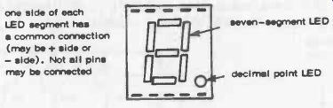
Fig. 10-9.
Typical LED display, as used in calculators, etc. The eight LEDs are internally
connected to a common cathode or common anode pin. one side of each LED segment
has common connection (may be + side or - side). Not all pins may be connected
seven-segment LED decimal point LED.
LIQUID CRYSTAL
The liquid crystal overcomes this particular power limitation since it can be activated by very much lower power (actually a tiny amount of heat, which can be produced by an equally tiny amount of electrical energy). Also, the display can be made much larger while still working at microscopic power levels, so that it can be left on all the time. The liquid crystal has its disadvantages, however. It is far less bright than an LED display, and also suffers from dark effect (like a neon lamp in this respect). Thus to be legible in dim light, the liquid crystal display needs to be illuminated by a separate light course.
Liquid crystal displays operate with low voltage and low current.
Current drain can be as little as 1 microamp (1 µA) per segment. A later development, the field-effect liquid crystal, can work on even lower voltages drawing microscopic currents (of the order of 300 nA), again making them an attractive choice for battery-powered displays. The field-effect liquid crystal also has better contrast, giving a black image on a light background.