AMAZON multi-meters discounts AMAZON oscilloscope discounts
The flow of electric current through any conductor has the effect of generating a magnetic field. This creation of magnetic energy represents a power loss during the time that field is being created, which is measurable in terms of a "voltage drop" or back emf. This is quite different (and additional) to the voltage drop produced by the resistance of the conductor, and disappears once stable conditions have been reached. Thus, in a dc circuit, the back emf tends to prevent the current rising rapidly when the circuit is switched on. Once a constant magnetic field has been established, the back emf disappears since no further energy is being extracted from the circuit and transferred to the magnetic field.
In the case of an ac circuit, the current is continually changing, creating a back emf which is also changing at a similar rate. The value of the back emf is dependent both on the rate of change of current (frequency) and to a factor dependent on the form of the conductor which governs its inductance.
Inductance is thus another form of resistance to ac, generated in addition to the pure resistance.
Every conductor has inductance when carrying ac, although in the case of straight wires this is usually negligible (except at very high frequencies).
If the wire is wound in the form of a coil, however, its inductance is greatly increased. If the coil is fitted with an iron core, then its inductance will be even higher for the same number of turns and coil size.
With the ac flowing through the coil, the "resistive" condition established is not as drastic as may appear at first sight. The polarity of the back emf is always such as to oppose any change in current. Thus while the current is increasing, work is being done against the back emf by storing energy in the magnetic field. On the next part of the current cycle when the current is falling, the stored energy in the magnetic field returns to the circuit, thus tending to keep the current flowing, see Fig. 7-1. An inductance, in fact, may be a very good conductor of ac, especially when combined with a capacitor in a tuned circuit (see later). On the other hand, it may be designed to work as a "resistive" component or choke.
The inductance of a single -layer coil, wound with space between adjacent turns can be calculated from the formula:
R2 N2 L= 9R + 10L
…where ... L is the inductance in microhenrys
R is the radius of the coil in inches
N is the number of turns
L is the length of the coil in inches.
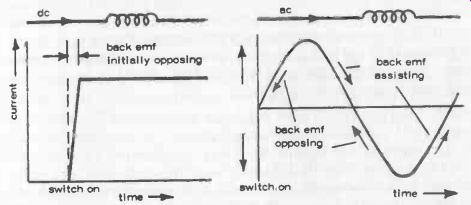
Fig. 7-1. Back emf induced in a dc circuit on switching on exists only momentarily.
In an ac circuit the back emf is continually changing.
Written as a solution for the number of turns required to produce a given inductance with R and L predetermined:
N = __/ (9R + 10L) x L / R^2
This formula applies regardless of the actual diameter of the wire used (also it does not matter whether bare wire or insulated wire is used), provided the coil diameter is very much larger than the wire diameter. For practical sizes of wires used for coil winding, this means a minimum coil diameter of at least 1 inch (25mm).
For smaller diameter coils, the wire size will have an increasing modifying effect on the actual inductance, and even the length of leads at the ends of the coil can upset the calculation. Thus such coils are normally designed on empirical lines (i.e., based on a specified number of turns of a given size of wire known to produce a given inductance when wound on a specific form diameter).
In practice, small coils are normally wound on a form intended to take an iron core. The position of this core is adjustable, relative to the wound, coil, by screwing in or out. Thus the actual value of inductance can be varied, for tuning purposes--Fig. 7-2 (left).
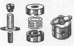
Fig. 7-2. Coil form (left) and pot cores (right).
Alternatively a pot core may he used where the coil is wound on a form or bobbin, subsequently enclosed in an iron housing. Provided the specific inductance of the pot core is known (it is usually specified by the manufacturer), the number of turns (A) to be used for the winding can be calculated with good accuracy from the formula:
N
=At J-17
... where L is the inductance required, and AL is the quoted specific inductance of the pot core in the same units as L.
Practical values of inductance used in electronic circuits may range from microhenrys (in medium and high frequency circuits) to millihenrys (in low frequency circuits), up to several henrys for chokes in power supply circuits. Normally, an inductance will be wound from the largest diameter enameled wire it is convenient to use (and still get the required number of turns on the form or bobbin), because this will minimize ohmic resistance and thus improve the efficiency or Q -factor of the coil.
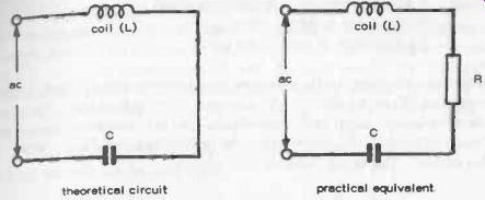
Fig. 7-3. Components which make a resonant circuit.
RESONANT CIRCUITS
A coil (inductance) and a capacitor connected in series across an ac supply has the very important characteristic that it is possible for the reactive effect of one to cancel out the reactive effects of the other. Thus in the "demonstration" circuit shown in Fig. 7-3, L is the inductance, and C the capacitor connected across a source of ac, the frequency of which can be varied. A resistor (R) is shown in series with L and C, as an inevitable part of a practical circuit.
If the ac supply is adjusted to a low frequency, the capacitive reactance will be very much larger than R, and the inductive reactance will be much lower than R (and thus also very much lower than the capacitive reactance).
See Section 3 for the formulas for capacitive and inductive reactance, and how these values are dependent on frequency.
If the ac supply is adjusted to a high frequency the opposite conditions will apply-inductive reactance much larger than R, and capacitive reactance lower than R and L. Somewhere between these two extremes there will be an ac frequency at which the reactances of the capacitance and inductance will be equal, and this is the really interesting point. When inductive reactance (XL) equals capacitive reactance (Xc), the voltage drops across these two components will be equal but 180 degrees out of phase. This means the two voltage drops will cancel each other out, with the result that only R is effective as total resistance to current flow. In other words, maximum current will flow through the circuit, determined only by the value of R and the applied ac voltage.
Working under these conditions, the circuit is said to be resonant. Obviously, resonance will occur only at a specific frequency, which is thus called the resonant frequency. Its value is given by the simple formula:
f= 1
-=
tar LC
…where…
f = resonant frequency in Hz
L = inductance in henrys
C = capacitance in farads.
A more convenient formula to use is:
10^6
f=
2/TV LC
…where ….
f = resonant frequency in kilohertz (kHz)
L = inductance in microhenrys (LH)
C = capacitance in pico farads (pF) .
Note that the formula for resonant frequency is not affected by any resistance (R) in the circuit. The presence of resistance does, however, affect the Quality factor or Q of the circuit. This is a measure of how sharply' the circuit can be tuned to resonance, the higher the value of Q the better, in this respect. The actual value of Q is given by:
Q= X R
….where X is the reactance in ohms of either the inductance or capacitance at the resonant frequency (they are both the same, so it does not matter which one is taken) and R is the value of the series resistance in ohms.
The practical resonant circuit (or tuned circuit) is based on just two components--an inductance and a capacitor. Some resistance is always present, however. At low to moderately high frequencies, most of this resistance will come from the wire from which the coil is wound. At very much higher frequencies, the majority of the resistance may come from the frequency energy loss in the capacitor.
TUNED CIRCUITS
The combination of an inductance and capacitance in series is the standard form of tuned circuit used in almost every radio receiver. It is drawn as shown in Fig. 7-4. At first, this would appear to show the coil and capacitor in parallel connection. However, the effective circuit is the "loop," which means that the coil and capacitor are effectively in series.
To make the circuit tunable over a range of resonant frequencies, either component can be a variable type. The usual choice for antenna circuits is to make the capacitor variable. In practice, the coil may also have theoretical circuit practical equivalent variable characteristics.
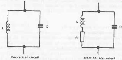
Fig. 7-4. Theoretically, only a capacitor and inductance
are involved in a resonant circuit. In practice, some resistance is always
present as well.
It is usually wound on a sleeve fitted on a ferrite rod, and capable of being moved up and down the rod, providing a means of varying the effective inductance. Once an optimum position has been found for the coil, it is cemented to the rod. In other words, the "variable" characteristics of the coil are used only for initial adjustment. After that, all adjustment of resonant frequency, or tuning, is done by the variable capacitor.
To assist in selecting suitable component values, the resonant frequency formula can be rewritten:
LC – 10 ^12 47,2 ... where ... L is in microhenrys, C is in picofarads, and f is the frequency in kHz .
Maximum values of variable capacitor used are normally 300 pF or 500 pF.
The working formula for calculating a matching inductance value is:
L(microhenrys) - 10 47 T2e C
As an example, suppose the tuned circuit is to be designed to cover the medium waveband, or frequencies from 500 to 1,600 kHz; and a 500 pF tuning capacitor is to be used. It follows from the resonant frequency formula that maximum capacitance will correspond to the lowest resonant frequency (with a fixed inductance), which in this case is 500 kHz. Inserting these values in the working formula:
10^12 L(microhenrys) = 4 pi ^2 x (500)2 x 500
= 200
Now check the resonant frequency when the capacitor is turned to its minimum value (which will probably be about 50 pF, associated with this value of inductance:
f 10^12 4 pi ^2 LC
= I 4 pi ^2 x 200 x 50 10^12
= 1 ,600 kHz
This shows that a 50-500 pF variable capacitor will "tune" the circuit from 1500 kHz (the highest frequency), down to 500 kHz satisfactorily. In other words, it covers the whole of the medium wave broadcast band.
If the final results achieved in the circuit do not provide quite the coverage required, for example, a station near one end of the band is not picked up, then there is still the possibility of "shifting" the frequency coverage in one direction or the other by adjusting the inductance (i.e., sliding the coil up or down the ferrite rod).
There are other types of tuned circuits which normally require adjustment only when initially setting up. These normally employ a "tunable" inductance (e.g., a coil wound on a form with an adjustable powdered -iron core). Such circuits may also be tuned by a trimmer capacitor; or both a trimmer capacitor and tunable inductance. The latter combination provides double tuning.
SERIES-RESONANT CIRCUITS
Another arrangement of the coil-capacitor combination is to connect them in series, Fig. 7-5. This produces a series -resonant circuit wherein the reactances of the coil and capacitor are again equal but opposite. The difference is that it presents a low impedance at the terminals of the circuit (top and bottom). This low impedance has the effect of shunting the ac frequency of resonance out of the circuit.
Frequencies other than the resonant one are not affected by the tuned circuit, as the off-resonance impedance is undisturbed.
A common use for this type of circuit is to remove, or reduce in amplitude, any unwanted signals, while allowing all others to pass. A popular application of the series -resonant circuit is in the antenna or rf-amplifier stages of receivers, where it is often called a "wave -trap." It can also be used quite effectively in transmitter power -amplifier stages to trap unwanted multiples (harmonics) of the fundamental frequency of operation.
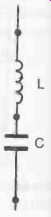
Fig. 7-5. A series -resonant circuit The impedance across the terminals of
the circuit is very low at the frequency of resonance; at the connection between
the capacitor and inductor, the impedance is very high. The capacitor is usually
the variable element in this arrangement.
RADIO -FREQUENCY CHOKES
A radio frequency choke (rfc) is a coil or inductance so designed that it has a relatively low ohmic resistance but a very high reactance at radio frequencies. It can thus pass dc but will block high frequency ac when the two are present in the same circuit-Fig. 7-6. In other words, it really works the opposite to a capacitor as a circuit element in this respect.
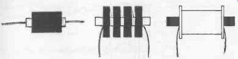
Fig. 7-6. Typical appearance of chokes wound on a ferrite core.
The characteristics of any rfc will vary with frequency. At high frequencies it will have characteristics similar to that of a parallel -resonant circuit; and at low frequencies characteristics similar to that of a series-resonant circuit. At intermediate frequencies, it will have intermediate characteristics. The actual characteristics are relatively unimportant when an rfc is used for series feed because the rf voltage across the choke is negligible. If used for parallel feed (where the choke is shunted across a tank circuit), it must have sufficiently high impedance at the lowest frequencies and no series-resonance characteristics at the higher frequencies in order to reduce power absorption to a suitable level. Otherwise, there will be a danger of the choke being overloaded and burned out.
Chokes designed to maintain at least a critical value of inductance over the likely range of current likely to flow through them are called swinging chokes. They are used as input filters on power supplies to reduce "ripple," or residual ac content. Chokes designed specifically for smoothing ripple, and having a substantially constant inductance, independent of changes in current, are known as smoothing chokes.