AMAZON multi-meters discounts AMAZON oscilloscope discounts
A transformer consists of two coils so positioned that they have mutual inductance. This magnetic "coupling" effect can be further enhanced by winding the two coils on a common iron core, see Fig. 8-1. The coil which is connected to the source of supply is called the primary (winding), and the other coil is called the secondary (winding). In order to transfer electrical energy from primary to secondary, the magnetic field must be continually changing, i.e., the supply must be ac.
One of the most useful characteristics of a transformer is its ability to provide step-down (or step-up) of ac voltages. The step-down (or step-up) ratio will be proportional to the number of turns in each coil:
V = n /n x V s s p
…where…
V = secondary voltage
n = number of turns on secondary
n = number of turns on primary
V = primary voltage.
The currents flowing in the primary and secondary follow a similar relation ship, but in opposite ratio:
I = n /n x I spsp
….where…. I = secondary current
I = primary current.
In other words, a step-down in voltage produces a step-up in current, an vice versa.
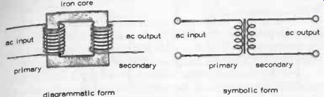
Fig. 8-1. The simple iron -cored transformer. -- diagrammatic form symbolic
form
In practice, there will always be some losses due to the resistance of the coils and energy lost in hysteresis and eddy currents in the core (in the case of an iron -cored transformer), and also from reactance caused by a leak of inductance from both coils. Thus, the power which can be taken from the secondary is always less than the power put into the primary, the ratio of the two powers being a measure of the efficiency of the transformer.
Typically, efficiency may range from 60 percent upwards, but is not necessarily constant. A transformer is usually designed to have its maximum efficiency at its rated power output. Its actual efficiency figure will decrease if the output is higher or lower. This loss of power appears in the form of heat. Thus, overloading a transformer can both reduce its efficiency and increase the heating effect. Operating at reduced output has no harmful effect, except for reducing efficiency because the actual power loss (and thus heating effect) is lowered.
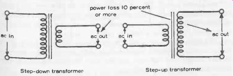
Fig 8-2. Step-down and step-up transformers defined. In practice, transformers
are often drawn in symbolic form with both coils of the same length, regardless
of actual turns ratio. Step-down transformer Step-up transformer
TRANSFORMERS AS POWER SUPPLIES
By selecting a suitable turns ratio, a transformer can be used directly to convert an ac supply voltage into a lower (or higher) ac output voltage at efficiencies which may be as high as 90 percent, Fig. 8-2. There are also applications where a 1:1 turns ratio transformer is used, providing the same ac output voltage as the ac input voltage, where it is desirable to "isolate" the supply from the output circuit. All transformers do, of course, provide physical separation of input and output circuits, but the degree of isolation safety is very much dependent on the actual construction of the transformer.
The more usual power-supply application of a transformer is to step_ down an ac voltage into some lower dc voltage output. The transformer will only provide voltage conversion. Additional components are needed in the output circuit to transform the converted ac voltage into a dc voltage. ,rig Two basic circuits for doing this are shown in Fig. 8-3. The first uses a single diode and provides half -wave rectification, passing one half of each ac cycle as dc and suppressing the other half cycle. The purpose of the capacitor is to maintain the dc voltage output as far as possible by discharging on each "suppressed" half cycle, and for this a large value capacitor is required. Although a very simple circuit, it has the inherent disadvantage of generating high peak voltages and currents, especially if a high current is drawn from the output. Also, the dc output is far from smooth. It will have a "ripple" at the ac frequency.
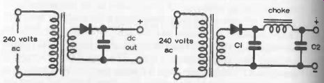
Fig. 8-3. Half -wave rectification of ac.
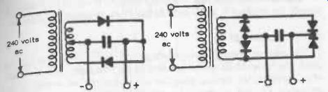
Fig. 8-4. Full -wave rectification of ac.
Much can be done to smooth the output by adding an inductance or choke and a second capacitor, as shown in the second diagram. These two components work as a filter (see also Section 6). The design of the choke has to be specially matched to the requirements, offering low resistance to dc without becoming saturated, which could reduce its inductance. In particular circuits the inductance may be a swinging choke, when it is possible to eliminate the reservoir capacitor C1.
The first diagram of Fig. 8-4 shows a simple full -wave rectifier circuit added to the transformer (the secondary of which must be center tapped).
For the same secondary voltage as the half-wave rectifier, the dc output voltage is now halved, but the current which can be drawn for a given rectifier rating is doubled. The reservoir capacitor charges and discharges alternately. This will produce a smoother dc supply, but ripple will still be present and in this case is equal to twice the ac frequency.
The more usual form of full-wave rectifier is the bridge circuit, shown in the second diagram of Fig. 8-4. This gives approximately the same no-load voltage as a half-wave rectifier with the advantage of full-wave rectification and better smoothing.
A practical circuit of this type is shown in Fig. 8-5. A single high value electrolytic capacitor is used for smoothing. Additional smoothing between stages fed from such a power supply may be provided by a resistor associated with a decoupling capacitor (like Fig. 8-3). The resistor value can also be chosen to drop a specific amount of voltage if the previous stage(s) do not require the full power-supply output voltage.
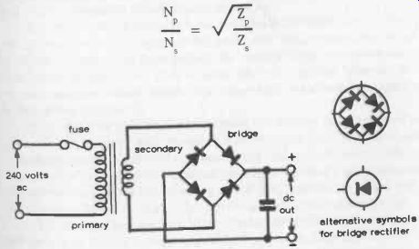
Fig. 8-5. Practical power -supply circuit. A high value capacitor is used.
The four diodes are bought as a single component called a bridge rectifier.
TRANSFORMERS AS COUPLING DEVICES
Transformers are very useful coupling elements for ac circuits. As well as providing coupling they can step-up a voltage or current, and even more important for impedance matching. By choosing the proper turns ratio, the impedance of a fixed load can be transformed to any desired higher or lower impedance, within practical limits. This can be a particularly important requirement when coupling transistor radio stages.
For impedance matching, the following relationship applies:
…where Z is the impedance of the transformer looking into the primary terminals Zs is the impedance of the load connected to the secondary of the transformer For impedance matching, it is therefore necessary to design the primary to provide the required ; and select the turns ratio to satisfy the equation.
AUTOTRANSFORMERS
An autotransformer is a one-winding coil with an intermediate tapping point. The full length of the coil (usually) forms the primary, and the length of coil between the tapping point and one end of the coil serves as the secondary, Fig. 8-6. It works on exactly the same principle as a conventional transformer, with the voltage developed across the output proportional to the turns ratio of this length of coil to the full length of coil.

Fig. 8-6. The autotransformer is a single full-length coil with a tapping
point.